Assignment 6 – James Kyle

Daylight Level Indicator:

For this assignment, I have made a theoretical daylight level sensor. The inspiration for this comes from my lab being in the basement of Ansys. We have no windows down there so I can easily get sucked into work and stay there for hours without realizing what time of day it is and/or whether it is time to pack up and call it a day. This daylight level indicator is meant to solve this problem by sensing the amount of daylight coming from outside and physically turning a dial to show the time of day. Theoretically, this dial would take the shape of a circle with night and day images on either side. The servo would turn to the appropriate position to indicate how close the sun is to setting or rising depending on the level of light outside and the time of day.

#include <Servo.h>


int hours = 0;

const int measurementNumber = 20;
int measurementCount = 0;
int lightMeasurements[measurementNumber];
const int lightLevel = A0; //Light level pin (photoresistor pin)

int lightBottomBound = 0;
int lightTopBound = 0;


Servo myServo;
int SERVOPIN = 9;


void setup() {

  pinMode(lightLevel, INPUT);

  myServo.attach(9);

}

void loop() {

  //Update measurement counter
  if (measurementCount < measurementNumber) {
    measurementCount += 1;
  } else {
    measurementCount = 0;
  }


  //Update light level average
  int lightLevelSum = 0;
  for (int i = 1; i < measurementNumber; i++) {
    lightLevelSum += lightMeasurements[i];
  }

  int lightLevelAverage = lightLevelSum / measurementNumber;


  //Update light level measurements
  int currentLightLevel = analogRead(lightLevel);
  lightMeasurements[measurementCount] = currentLightLevel;


  //Change bounds if light level is outside of bounds
  if (lightLevelAverage < lightBottomBound) {
    lightBottomBound = lightLevelAverage;
  }

  if (lightLevelAverage > lightTopBound) {
    lightTopBound = lightLevelAverage;
  }


  //Write to servo
  int servoAngle = map(lightLevelAverage, lightBottomBound, lightTopBound, 0, 180);
  myServo.write(servoAngle);


  delay(1000);

}


Assignment 5 – Jud

The idea for this sensor reading is to read the noise level in a room and detect whether it would be damaging to someone’s hearing. For the average human ear, a sustained noise level over 70dB or a burst of sound over 120dB can cause harm to the human ear. In order to counteract this, I used a speaker sensor connected to an Arduino to read the noise level in a room and decide whether either of these conditions have been met. If they have then an LED would turn on. So far I have gotten the speaker to read data but I haven’t been able to translate this data into decibels at the moment. The sensor I am currently using measures the noise level in its output by varying the signal to a degree relative to the amount of noise being detected. So if there is a high noise level, the sensor gives data that looks like the following:

If there is a low noise output, the data looks more uniform like a straight line.

I attempted to write a script that would look at the change in this data and use a filter to smooth the delta calculation but this didn’t work very well when I tried it out. My next idea would be to take a moving average of the data over time and then take the max and min of that range as the magnitude of the noise level. With this magnitude, it could then be converted into decibels through tuning of an equation.

//Define Accelerometer Variables for pins
#define MICROPHONE   A0

double speakerLevel = 0;
double prevSpeakerLevel = 0;
double delta = 0;
double prevDelta = 0;

double alpha = 0.8;


void setup() {
  //Setup pins as inputs

  pinMode(MICROPHONE, INPUT);
  
  Serial.begin(9600);

}

void loop() {

  speakerLevel = analogRead(MICROPHONE);
  delta = abs(speakerLevel - prevSpeakerLevel);

  speakerLevel = alpha*speakerLevel + (1-alpha)*prevSpeakerLevel;

  delta = alpha*delta + (1-alpha)*prevDelta;

  prevDelta = delta;
  
  Serial.println(speakerLevel);
//  Serial.println(delta);
  
}


Assignment 5: Smoothing Sensor Data

For assignment 5, I sampled temperature and humidity data points from the DHT22 sensor to create average temperature and humidity values. I used the serial monitor within Arduino IDE to follow changes in values and added characters to distinguish visually between temperature, temperature average, humidity, and humidity averages within the serial monitor.

Then I used the values from the average temperature (with an average of 10 data points) to calculate a temperature change over a period of values.  If the temperature change was greater than 3 degrees within the specified sampling period, the ‘alarm’ (an LED light) would turn on. It would turn off again when the temperature change fell below 3 degrees.

The limitations of this method are that slow and steady change in one direction to an average may not be detected. The data smoothing is desirable to avoid ‘blips’ from occurring, but it may be preferable for environmental alarms (temperature, smoke, etc) to compare their average sampling to a constant value that reflects the preferred conditions – not only a rapid change in values. As observed in the paragraph above, when using this technique, the ‘alarm’ turns off if the temperature change falls back below the threshold of acceptable change. This may or may not be desirable, depending on the response needed.

Final Code:

#include <DHT.h>
#include <DHT_U.h>
#define DHTPIN 2        // sensor DHT22 data connected to Arduino pin 2
#define DHTTYPE DHT22  // using sensor DHT22


DHT dht(DHTPIN, DHTTYPE);  //dht library 
int chk;
int humid; //stores humidity
int tempC; //stores temperature
int tempF; //stores temp in F


//data smoothing
//based on https://docs.arduino.cc/built-in-examples/analog/Smoothing 
//include dht library 
//note this tutorial is for analog sensors not digital like the dht22

const int numReadings = 10;
int tempReadings [numReadings];
int tempReadIndex = 0;
int tempTotal = 0;
int tempAverage = 0; 


int humReadings [numReadings];
int humReadIndex=0;
int humTotal = 0;
int humAverage = 0; 


int inputPin= 2; //put sensor pin here

//const char tNow="Temperature: ";
//const char tAvg="Average Temperature: "; 

//4 lines below only print T, A, H, and v
const char*tempNow="Temperature: ";
const char*tempAvg="Average Temperature: ";
const char *huNow="Humidity: ";
const char *huAvg="verage Humidity: ";

//detecting sensor change
int last; 

//response to sensor change
int blueled=10;

void setup() {

  // put your setup code here, to run once:
  Serial.begin(9600);
  dht.begin(); 

  //for response to sensor change
  pinMode(blueled,OUTPUT);

  for (int thisReading = 0; thisReading < numReadings; thisReading++) {
    tempReadings[thisReading]= 0;
    humReadings[thisReading]=0;
    //placing humreadings below temp readings does not appear to work
    //humReadings[thisReading]=0;
  //for (int hThisReading = 0; hThisReading < numReadings; hThisReading++) {
    //humReadings[hThisReading]= 0;

  }

}

void loop() {
  // put your main code here, to run repeatedly:

humid=dht.readHumidity();
tempC=dht.readTemperature();
//tempF=(tempC*1.8)+32;
//Serial.write(tempC);
delay(2000);
//delay needed for p5js to recieve 2 values separately
//Serial.write(humid);
//delay(1000);

  tempTotal = tempTotal - tempReadings[tempReadIndex];
  //need 2 reads start with one use temp
  tempReadings[tempReadIndex] = tempC;
  tempTotal = tempTotal + tempReadings [tempReadIndex];
  tempReadIndex = tempReadIndex + 1; 

  if (tempReadIndex >= numReadings) {
    tempReadIndex = 0; 
   
  }

  tempAverage = tempTotal / numReadings;

  humTotal = humTotal - humReadings[humReadIndex];
  humReadings[humReadIndex] = humid;
  humTotal = humTotal + humReadings [humReadIndex];
  humReadIndex = humReadIndex + 1;


  if (humReadIndex >= numReadings) {
    humReadIndex=0;
  }

  humAverage = humTotal / numReadings;


//printing to serial monitor

  //const char* pNowTemp = tNow + tempC;
  //const char* pAvgTemp = tAvg + tempAverage;
  //setDisplayToString(pNowTemp);
  //tempAverage.setDisplayToString(pAvgTemp);
  //Serial.print(f'Avg: ');
  
  //one line below printed just A
  Serial.print(*tempAvg);
  Serial.println(tempAverage);
 
  //Serial.print(F('Average temperature {tempAverage}'));
  //Serial.print(F('Average temperature:'));
  //Serial.println(tempAverage);

  //Serial.println(pNowTemp);
  delay(5);

  //two lines below printed just T 
  Serial.print(*tempNow);
  Serial.println(tempC);

  //Serial.println(pAvgTemp);

  delay(5);

  Serial.print(*huAvg);
  Serial.println(humAverage);

  Serial.print(*huNow);
  Serial.println(humid);

  delay(5);

//measuring change in temperature average
  int t = tempAverage;
  int tdiff = t-last;
  int thresh = 1;
  Serial.println(tdiff);
  //this statement could be simplified, need to do it for all tdiff values 
  if(tdiff>thresh||tdiff<=thresh){
    Serial.println(t);
    last=t;


//led response to rate of change in temperature average
 if (tdiff>=3)
  {
    digitalWrite(blueled,HIGH);

  }
if(tdiff<3)
  {
  digitalWrite(blueled,LOW);
 }
  }


}

Process Notes:

Identifying Change in Average Temperature Value

Printing Change in Average Temperature Value

LED on/off with Changes in Average Temperature Value


LED doesn’t turn off when Change in Average Temperature = 0

Solution: Turning Off LED when Change = 0


Assignment 5: smooth and parse data then display a result

Take physical input over time from sensor(s), smooth and parse the data in way to make it usable/accessible.

You can “fake” sensors for safety.  If you want to make a “smoke detector” detect the relative humidity and note significant changes (like from taking a shower) as if they were dangerous levels of smoke.

Interaction has emotional meaning.  Can you create an emotional data feed?  An emotional output?

Due by midnight, Monday, 14 Feb, 2022

Making An Open Window More Accessible

Making An Open Window More Accessible

Description:

The idea behind these two sketches is to have the ability to open a window via a slider on some interface. In place of a fully working window opening mechanism is a motor with an encoder wired up to an Arduino. This Arduino then uses serial communication to relay its current position back to a p5.js sketch and retrieve its goal position from that sketch as well. The goal position is determined by an on screen slider that moves around then the user clicks and drags the slider.

While I was able to get the motor moving to a specific degree based off of serial input through the Arduino serial command, I was not able to get the p5 sketch to communicate in such a way that the Arduino could read it and then interpret it into an actionable item. I was also not able to send data from the Arduino to the p5 sketch but instead was only able to communicate with the p5 serial application shown in the demo below. Despite all this non-functional code, however, I was able to code a working slider into the p5 sketch and convert the x position of the slider into a percent of 100 as it is dragged across the screen.

Demo:

Schematic:

Code:

*
  Making Things Interactive
  Assignment 4
  Judson Kyle (judsonk)
  02/07/2022

  Collaboration and sources:
  - Encoder_Interrupts functions copied from 24-354 Gadgetry lab code

*/

// Pin Variables

#define encoderPinA   2
#define encoderPinB   3
#define motorPin1     10
#define motorPin2     11
#define motorPWM      9

int encoderCount = 12 * 98; //12 encoder counts per revolution with 1:98 gear ratio
int incomingByte = 0;

// https://www.pololu.com/product/4824
float gearRatio = (22.0*20.0*22.0*22.0*23.0)/(12.0*12.0*10.0*10.0*10.0); 

bool motorSpinning = false;

// Motor distance measuring variables
volatile long currentEncoder_pos_f = 0, prevEncoder_pos = 0, revs = 0;
float motorCurPos = 0;

//PID Variables
float ep = 0; //Proportional error
float ei = 0; //Integral error
float ed = 0; //Derivative error
float prev_ep = 0;
double curTime = 0;
double prevTime = 0;

int pwmCmd = 0;

float motorGoalPos = 0; // desired angle [radians]
float kp = 50; // P gain
float ki = 0; // I gain
float kd = 0; // D gain

void setup() {

  //Initialize serial communication:
  Serial.begin(9600);

  //Initialize motor control pins
  pinMode(motorPin1, OUTPUT);
  pinMode(motorPin2, OUTPUT);
  pinMode(motorPWM, OUTPUT);

  //Initialize interrupts
  attachInterrupt(digitalPinToInterrupt(encoderPinA), encoderA, CHANGE);
  attachInterrupt(digitalPinToInterrupt(encoderPinB), encoderB, CHANGE);
}

void loop() {
  if (Serial.available() > 0){
    incomingByte = Serial.parseInt();
    if (incomingByte > 0 && incomingByte != motorGoalPos) {
       motorGoalPos = (float)incomingByte/100;
    }
  }
  
  //Update motorActualPos variable to reflect actual motor position in radians
  motorCurPos = (((float) currentEncoder_pos_f) / (4 * ((float) encoderCount))) * 3.14159*gearRatio/8; // Convert encoder counts to distance travelled

  Serial.println(motorCurPos);
  //PID controller to get motor to position
  // ----------------------- CONTROLLER CODE --------------
  // PID Controller
  curTime = millis();
  ep = (motorGoalPos - motorCurPos); // error in position (p)
  ei = ei + ep; // integral error in position (i)
  ed = (ep - prev_ep) / (curTime - prevTime); // derivative error in position (d)

  prev_ep = ep;
  prevTime = curTime;

  pwmCmd = (ep*kp + ei*ki + ed*kd);

  // switch directions if pass set point
  if(ep < 0) {
    // Turn on motor A & B
    digitalWrite(motorPin1, LOW);
    digitalWrite(motorPin2, HIGH);
  }
  else {
    // Turn on motor A & B
    digitalWrite(motorPin1, HIGH);
    digitalWrite(motorPin2, LOW);
  }

  pwmCmd = abs(pwmCmd);
  if (pwmCmd > 255) {
    pwmCmd = 255;
  }
  analogWrite(motorPWM, pwmCmd);
  
//  Serial.print("Motor Position: ");
  //Serial.println(motorCurPos, 7);
}

void encoderA(){
  // look for a low-to-high on channel A
  if (digitalRead(encoderPinA) == HIGH) { 
    // check channel B to see which way encoder is turning
    if (digitalRead(encoderPinB) == LOW) {  
      
        currentEncoder_pos_f = currentEncoder_pos_f + 1;         // CW
    } 
    else {
        currentEncoder_pos_f = currentEncoder_pos_f - 1;        // CCW
    }
  }
  else   // must be a high-to-low edge on channel A                                       
  { 
    // check channel B to see which way encoder is turning  
    if (digitalRead(encoderPinB) == HIGH) {   
      
        currentEncoder_pos_f = currentEncoder_pos_f + 1;          // CW
    } 
    else {
        currentEncoder_pos_f = currentEncoder_pos_f - 1;          // CCW
    }
  }
}

void encoderB(){

  // look for a low-to-high on channel B
  if (digitalRead(encoderPinB) == HIGH) {   
   // check channel A to see which way encoder is turning
    if (digitalRead(encoderPinA) == HIGH) {  
       
        currentEncoder_pos_f = currentEncoder_pos_f + 1;         // CW
    } 
    else {
        currentEncoder_pos_f = currentEncoder_pos_f - 1;         // CCW
    }
  }
  // Look for a high-to-low on channel B
  else { 
    // check channel B to see which way encoder is turning  
    if (digitalRead(encoderPinA) == LOW) {   
        currentEncoder_pos_f = currentEncoder_pos_f + 1;          // CW
    } 
    else {
        currentEncoder_pos_f = currentEncoder_pos_f - 1;         // CCW
    }
  }
}
var serial;   // variable to hold an instance of the serialport library

// for macos and *nix, you'll do something like this:
//var portName = '/dev/cu.usbserial-DN01DW79';    // fill in your serial port name here

// for windows, just the COM port you're using
var portName = '/dev/tty.usbmodem144101';

var inData;   // variable to hold the input data from Arduino

var minWidth = 600;   //set min width and height for canvas
var minHeight = 400;
var width, height;    // actual width and height for the sketch
var squareWidth = 100;

var sliderLength = 200;
var sliderHeight = 100;
var sliderBackgroundStrokeWeight = 4;
var sliderBackgroundSideOffset = 100;
var sliderOffset = sliderBackgroundSideOffset + (sliderBackgroundStrokeWeight + sliderLength)/2;
var sliderX = sliderBackgroundSideOffset + sliderBackgroundStrokeWeight + sliderLength/2;
var sliderY;
var collision = false;
var windowActualPos = 0;
var windowGoalPos = 0;

var i = 0;

function setup() {
  // set the canvas to match the window size
  if (window.innerWidth > minWidth){
    width = window.innerWidth;
  } else {
    width = minWidth;
  }
  if (window.innerHeight > minHeight) {
    height = window.innerHeight;
  } else {
    height = minHeight;
  }

  sliderX = sliderOffset + sliderLength/2;
  sliderY = height/2;

  //set up canvas
  createCanvas(width, height);
  noStroke();

  //set up communication port
  serial = new p5.SerialPort();       // make a new instance of the serialport library
  serial.on('list', printList);  // set a callback function for the serialport list event
  serial.on('connected', serverConnected); // callback for connecting to the server
  serial.on('open', portOpen);        // callback for the port opening
  serial.on('data', serialEvent);     // callback for when new data arrives
  serial.on('error', serialError);    // callback for errors
  serial.on('close', portClose);      // callback for the port closing

  serial.list();                      // list the serial ports
  serial.open(portName);              // open a serial port
}

function draw() {
  drawBackgroundCanvas();

  //Draw slider background
  strokeWeight(sliderBackgroundStrokeWeight);
  stroke('grey');
  fill('white');
  rect(sliderBackgroundSideOffset, sliderY/2 - sliderHeight/2 - sliderBackgroundStrokeWeight, width - 2*sliderBackgroundSideOffset, sliderHeight + 2*sliderBackgroundStrokeWeight);

  //Draw actual slider
  strokeWeight(4);
  stroke('black');
  fill('grey');
  rect(sliderX - sliderLength/2, sliderY/2 - sliderHeight/2, sliderLength, sliderHeight);
}

//Initialize drawing canvas
function drawBackgroundCanvas() {
  // set background to black
  background(0);
    fill(255);
  textSize(30);
  textAlign(CENTER);
  text("Window Opener", width/2, 80);
  textSize(16);
  text("Degree open: " + Number(serial.read()), width/2, 100);    // displaying the input

  //Draw playing canvas
  strokeWeight(4);
  stroke('white');
  fill('black');
  noStroke();
}

function updateSliderPosition() {
  if (mouseX <= sliderOffset) {
    sliderX = sliderOffset;
  }
  else if (mouseX >= width - sliderOffset) {
    sliderX = width - sliderOffset; 
  }
  else {
    sliderX = mouseX;
  }
  windowGoalPos = (sliderX - sliderOffset)/(width - 2*sliderOffset);
  windowGoalPos = (windowGoalPos);
  serial.write(windowGoalPos);
}

// Following functions print the serial communication status to the console for debugging purposes

function printList(portList) {
 // portList is an array of serial port names
 for (var i = 0; i < portList.length; i++) {
 // Display the list the console:
 print(i + " " + portList[i]);
 }
}

function mousePressed() {
  updateSliderPosition();
}

function mouseDragged() {
  updateSliderPosition();
}

function serverConnected() {
  print('connected to server.');
}

function portOpen() {
  print('the serial port opened.')
}

function serialEvent() {
    // on the arduino we are using Serial.write to send an integer
    // so we have to use Number() to convert it to a number.
    // otherwise it would be a string
    inData = Number(serial.read());
    motorActualPos = inData;
    //  if you do this, the inData value will be a string, not a number
    // 
    //inData = serial.read();
    //
    // in arduino terms it's
    // int inData = 1;
    // vs
    // String inData = "1';
}

function serialError(err) {
  print('Something went wrong with the serial port. ' + err);
}

function portClose() {
  print('The serial port closed.');
}


Assignment 4: DHT 22 Temperature Sensor and LED

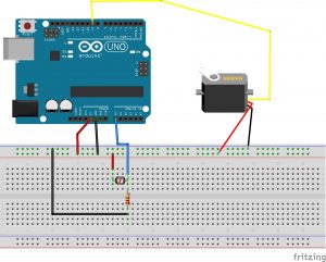
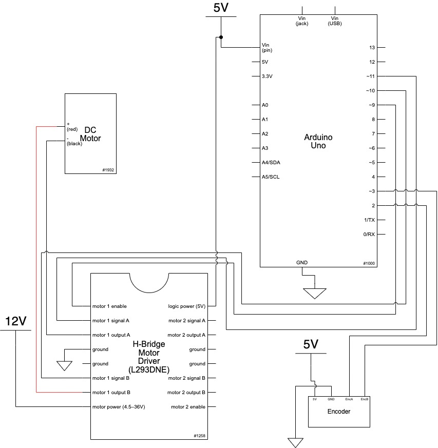
Before adding p5js to the operation, I set up a first iteration of input and output in Arduino.

The intention of the project is to measure environmental conditions and cue an alert when environmental conditions exceed a desired limit (too hot or too cold). This could have applications as a monitoring device during excessive heat waves. Based on temperature input from the sensor, the arduino  turns on a blinking warming light at a set temperature limit. For those seeking to use air-conditioning to a bare minimum (and save $), this system could act as a gauge that advises on serious conditions. Especially if someone is reliant on a window unit A/C instead of central air-conditions, it may encourage someone to seek a cooler environment and avoid risk of heat stroke.

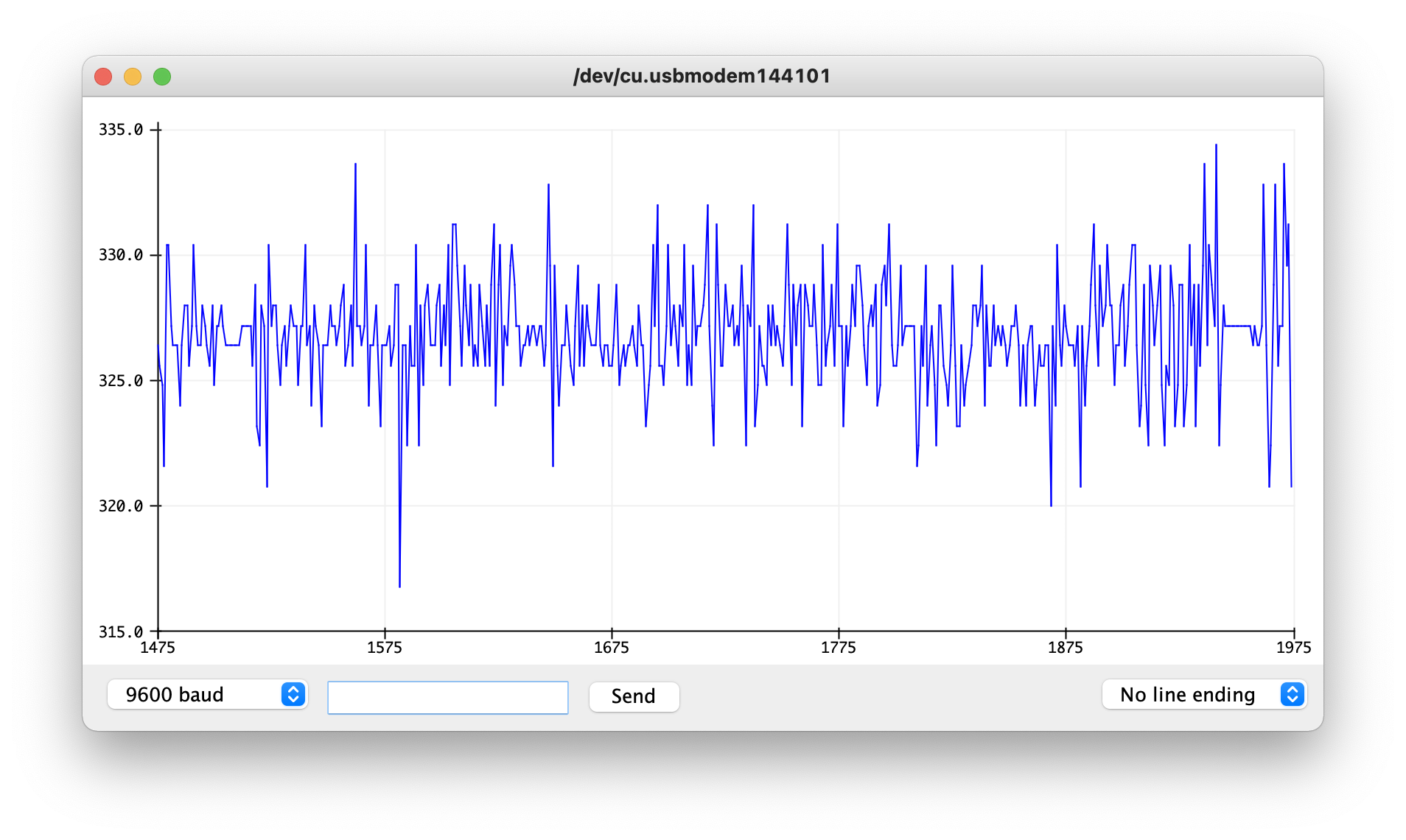
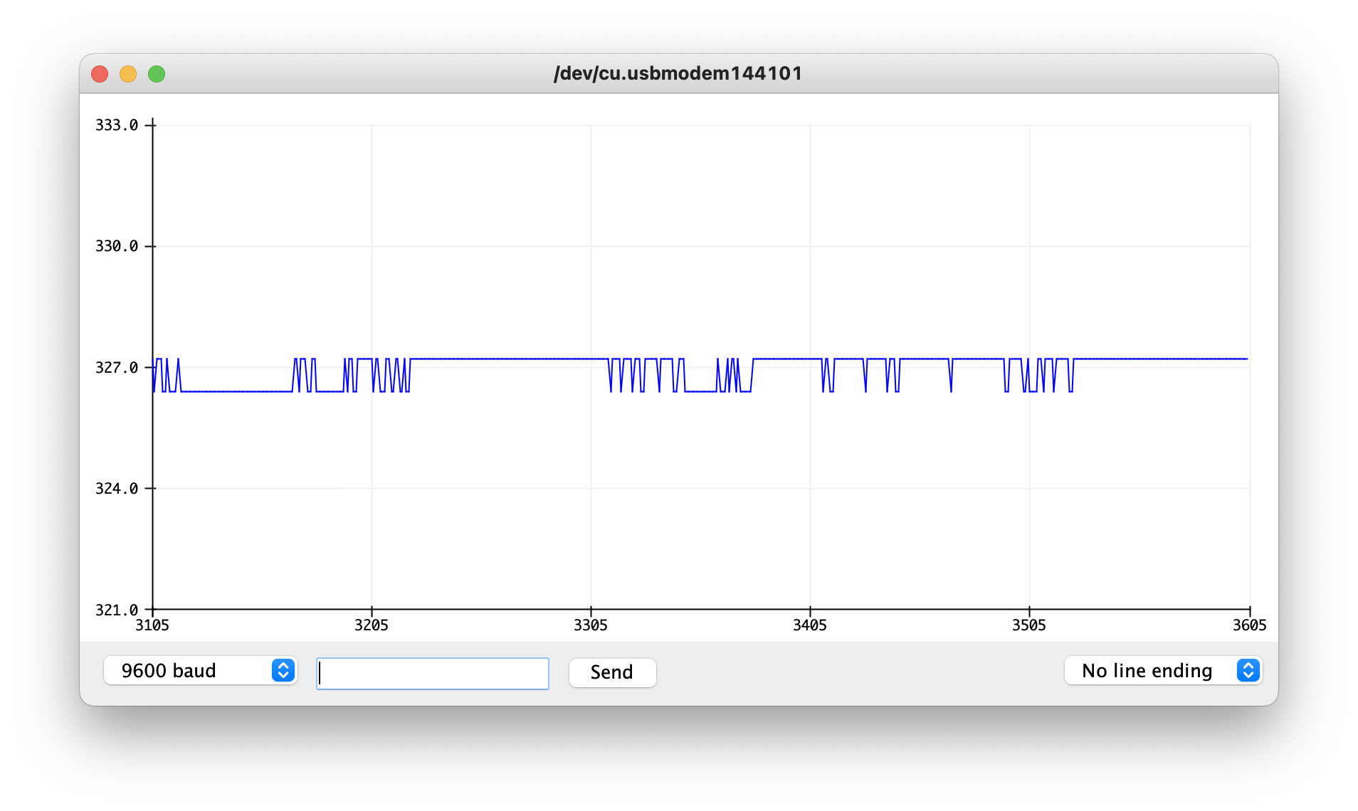
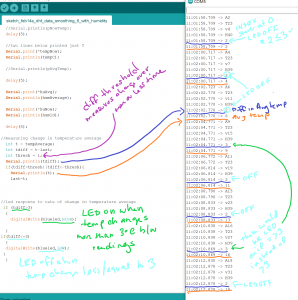
I used the sensor to capture temperature data in warm and cold spots in my apartment. At the time measured, there was about a 7 degree F difference between the kitchen (~72 degrees F) and the bedroom (~65 degrees F). Since this was the temperature differential currently present in my apartment, I used tempF>= 70 to test the code, moving between rooms. In the kitchen, the LED light blinked, indicating the temperature was equal to or greater than 70 degrees F (I also used the Arduino serial monitor to check readings as I moved around).


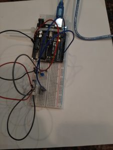
^DHT 22 Temperature and Humidity Sensor and LED

//

#include "DHT.h"   //adafruit dht library 
#define DHTPIN 2        // sensor DHT22 data connected to Arduino pin 2
#define DHTTYPE DHT22  // using sensor DHT22

DHT dht(DHTPIN, DHTTYPE);  //dht library 
int chk;
float humid; //stores humidity
float tempC; //stores temperature
float tempF; //stores temp in F
int blueled=10;


void setup() {
  pinMode(blueled, OUTPUT);
  Serial.begin(9600);
  dht.begin();


}

void loop() {
  //read dht22 data and store to variables humid and temp
  if (isnan(humid) || isnan(tempC) ||isnan(tempF)){
    Serial.println(F("Failed to read from DHT sensor"));
    delay(10000);
    return;
  }
// troubleshooting issues with getting nan reading from dht22
  humid=dht.readHumidity();
  tempC=dht.readTemperature();
//converting to fahrenheit
  tempF=(tempC*1.8)+32;
//printing temp and humid values to serial monitor
  Serial.print("Humidity: ");
  Serial.print(humid);
  Serial.print(" %, Temp: ");
  Serial.print(tempF);
  Serial.println("Fahrenheit");
  delay(2000);
  if (tempF >= 70){
    digitalWrite(blueled,HIGH);
    delay(150);
    digitalWrite(blueled,LOW);
    delay(75);
  }
 delay(2000); 


}

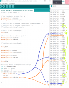
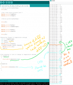
Arduino was a success. The LED light blinked on and off when temperature was above 70, and stayed off when temperature was less than 70.

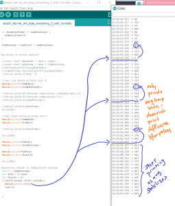
When I connected the p5.serial control, the console was printing out the serial print that had been set up on the arduino:

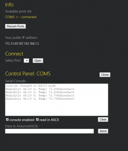
^first, I thought I would break out the second part of the arduino code (the control of the LED light) as data sent to arduino via p5. serial control. The library for DHT22 is all C++ and not clear to me initially how to modify. So as a first step, I tried to print sensor data on p5js.

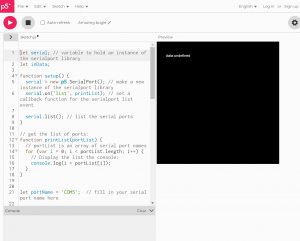
Reviewed two arduino/potentiometer/P5js tutorials (https://medium.com/@yyyyyyyuan/tutorial-serial-communication-with-arduino-and-p5-js-cd39b3ac10ce, https://itp.nyu.edu/physcomp/labs/labs-serial-communication/lab-serial-input-to-the-p5-js-ide/#Draw_a_Graph_With_the_Sensor_Values). I thought it would be interesting to use the information from the sensor to draw a graph, which would highlight changes in temperature or humidity. There was a lot that needed to be done to set up serial port, not sure if this is where everything went wrong, and my final result was undefined. I am wondering if this has to do with the DHT22 library being all C++ or if DHT 22 values need to be mapped to 0 to 255 before this information is read by P5 serial.


let serial; // variable to hold an instance of the serialport library
let inData;
 
function setup() {
  serial = new p5.SerialPort(); // make a new instance of the serialport library
  serial.on('list', printList); // set a callback function for the serialport list event
 
  serial.list(); // list the serial ports
}
 
// get the list of ports:
function printList(portList) {
  // portList is an array of serial port names
  for (var i = 0; i < portList.length; i++) {
    // Display the list the console:
    console.log(i + portList[i]);
  }
}


let portName = 'COM5';  // fill in your serial port name here
 
function setup() {
  serial = new p5.SerialPort();       // make a new instance of the serialport library
  serial.on('list', printList);  // set a callback function for the serialport list event
  serial.on('connected', serverConnected); // callback for connecting to the server
  serial.on('open', portOpen);        // callback for the port opening
  serial.on('data', serialEvent);     // callback for when new data arrives
  serial.on('error', serialError);    // callback for errors
  serial.on('close', portClose);      // callback for the port closing
 
  serial.list();                      // list the serial ports
  serial.open(portName);              // open a serial port
}

function serverConnected() {
  console.log('connected to server.');
}
 
function portOpen() {
  console.log('the serial port opened.')
}
 
function serialEvent() {
  inData=Number(serial.read());
 
}
 
function serialError(err) {
  console.log('Something went wrong with the serial port. ' + err);
}
 
function portClose() {
  console.log('The serial port closed.');
}

function setup() {
  createCanvas(400, 400);
}


function draw() {
  background(0);
  fill(255);
  text("data:"+ inData, 30, 50)
}


My references include:

https://www.arduino.cc/reference/en/libraries/dht-sensor-library/

https://stackoverflow.com/questions/40874880/getting-nan-readings-from-dht-11-sensor

https://create.arduino.cc/projecthub/mafzal/temperature-monitoring-with-dht22-arduino-15b013

https://www.instructables.com/How-to-use-DHT-22-sensor-Arduino-Tutorial/

https://itp.nyu.edu/physcomp/videos/videos-serial-communication/#Serial_to_p5js_in_binary

How to Set Up the DHT11 Humidity Sensor on an Arduino

Notes-

When looking for DHT22 and p5js, this project came up: https://github.com/TTurbo0824/pcom_final/blob/master/test_led_hum_serial.ino

^has a note for incorporating p5js but this just looks like what got uploaded to arduino, not additional p5js data sent


** 2/08/2022 Update:

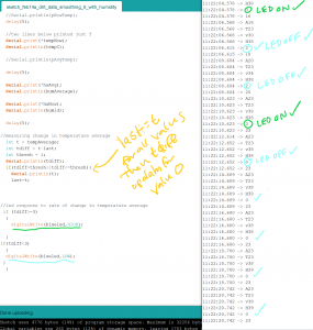
Serial port appears now to be connected to P5JS. I was able to use the test sketch from last week to check that the values for temperature (in C) came through, then both values for temperature and for humidity.

HOWEVER, while running the sketch in the browser editor, the data from the serial port is not registering.

New P5JS sketch:

let serial; // variable to hold an instance of the serialport library
let portName = 'COM5'
let inData;
 
function setup() {
  createCanvas(400,300);
  background('rgba(0,255,0, 0.15)');
  

}

  serial = new p5.SerialPort(); // make a new instance of the serialport library
  serial.on('list', printList); // set a callback function for the serialport list event
 
  serial.list(); // list the serial ports

 
// get the list of ports:
function printList(portList) {
  // portList is an array of serial port names
  for (var i = 0; i < portList.length; i++) {
    // Display the list the console:
    console.log(i + portList[i]);
    serial.on('list',printList);
    serial.on('connected', serverConnected); // callback for connecting to the server
  serial.on('open', portOpen);        // callback for the port opening
  serial.on('data', serialEvent);     // callback for when new data arrives
  serial.on('error', serialError);    // callback for errors
  serial.on('close', portClose);      // callback for the port closing
    
    
serial.open(portName);              
    // open a serial port
    
  function serverConnected() {
  console.log('connected to server.');
}
 
function portOpen() {
  console.log('the serial port opened.')
}
 
function serialEvent() {
  inData = Number(serial.read());
 
}
 
function serialError(err) {
  console.log('Something went wrong with the serial port. ' + err);
}
 
function portClose() {
  console.log('The serial port closed.');
}

    
  }
 

  function graphData(newData) {
  var yPos=map(newData,0,255,0,height)
  stroke(0xA8,0xD9,0xA7);
  line(xPos,height,xPos,height - YPos);
  if (xPos>=width) {
    xPos=0;
    background(0x08, 0x16, 0x40);
  } else {
    xPos++;
  }
  }  
 function draw() {
  graphData(inData);
  text("temperature in Celsius:" + inData, 1, 50);
  
} 
  
}


Assignment 4: Interaction with p5.js and Arduino

Create accessibility using an Arduino, sensors, p5.js, and a screen.

The context is you’re making something accessible or usable. We’re still in the early days so this can be rather abstract or a proof of concept.

Two parts to the assignment which can be implemented as two different sets of sketches.  If you can do both in one set of sketches, that’s great.

Use Arduino inputs to display something in a p5.js sketch.  A very simple example is a switch on the Arduino that detects a door being opened, and the Arduino asks the p5.js script to go from dark to light.

Use a p5.js sketch interract to make something happen on the Arduino: turn LEDs on/off, spin a motor, etc.  Imagine p5.js is a touch-screen and you’re making things happen across the room.

Due Monday, 7 Feb 2022, 11:59 pm.  We will discuss on Tuesday.

Fun With Interrupts – James Kyle

How it works:

I played around with buttons switches and potentiometers to change light blinking patterns and came up with this circuit. The switch has an interrupt which changes whether all lights blink at the same time or different times (a blink mode). The button changes which light blinks in the event that they are not blinking at the same time. The potentiometer changes the speed at which the lights blink.

I had some trouble with getting the switch interrupt to work more than once and I ended up having to place it before the button interrupt which I assume prioritizes it.


Code:

int toggle_color = 3;
int GREEN_LED = 7;
int YELLOW_LED = 6;
int RED_LED = 5;
int POT = A0;
int blink_rate = 250;
int toggle_blinkMode = 2;


//LED blinking variables
volatile int LED_pin = 5;
volatile bool individual_blink;


//Debounce variables
volatile unsigned long last_press = 0;
int wait_time = 50;


void setup() {

  Serial.begin(9600);

  //Initializing Pins
  pinMode(GREEN_LED, OUTPUT);
  pinMode(YELLOW_LED, OUTPUT);
  pinMode(RED_LED, OUTPUT);

  pinMode(toggle_color, INPUT_PULLUP);
  pinMode(POT, INPUT);


  //Interrupt initialization
  attachInterrupt(digitalPinToInterrupt(toggle_blinkMode), blinkMode, CHANGE);
  attachInterrupt(digitalPinToInterrupt(toggle_color), switchLED, CHANGE);


}

void switchLED() {

  //Turn off previous light
  digitalWrite(LED_pin, LOW);

  //Debounce
  if ((millis() - last_press) >= wait_time) {
    LED_pin++;
    last_press = millis();
  }

  //Go back to first light
  if (LED_pin > 7) {
    LED_pin = 5;
  }


}

void blinkMode() {

  if (individual_blink) {
    individual_blink = 0;
  } else {
    individual_blink = 1;
  }

}

void loop() {

  blink_rate = map(analogRead(POT), 0, 255, 100, 500);

  if (individual_blink) {
    digitalWrite(LED_pin, HIGH);
    delay(blink_rate);
    digitalWrite(LED_pin, LOW);
    delay(blink_rate);
  } else {
    digitalWrite(RED_LED, HIGH);
    digitalWrite(GREEN_LED, HIGH);
    digitalWrite(YELLOW_LED, HIGH);
    delay(blink_rate);
    digitalWrite(RED_LED, LOW);
    digitalWrite(GREEN_LED, LOW);
    digitalWrite(YELLOW_LED, LOW);
    delay(blink_rate);
  }

  bool value = individual_blink;
  Serial.println(value);


}


Messing Around With Interrupts

Messing Around With Interrupts:

Functionality:

There are two different states that the system can be put into. These states are controlled by an interrupt connected to the switch. When the switch is high, the system goes into adjustment mode where the user can use the potentiometer to adjust the brightness of the LED. This adjustment is only possible while in this state. When the switch is low, the system returns to its normal state where there is a blinking mode and solid mode. These modes are controlled by a second interrupt tied to the button. While in the blinking state, the LED’s flash individually for 0.5s each in a sequence of red to yellow to green and back to red. In the solid state, all of the LED’s remain on. The brightness of the LED’s in this mode is also the same as that set in the previous adjustment state.

Code:
/*  Interrupt Assignment 
 *  Judson Kyle 
 *  judsonk 
 *  01/31/2021 
*/
#define POT_PIN     A0
#define SWITCH      3
#define BUTTON      2

#define RED_LED     11
#define YELLOW_LED  10
#define GREEN_LED   9

#define RED     0
#define YELLOW  1
#define GREEN   2

volatile bool ADJUST_STATE = false;
volatile bool BLINK = false;

int potVal = 0;
double ledBrightness;

int currentLED = 0;

int waitTime = 500; //ms
long long startTime;

int buttonDebounceTime = 300;
long long buttonDebounceStart = 0;
volatile bool BUTTON_DEBOUNCE = false;
bool BUTTON_PREV_DEBOUNCE = false;


void setup() {
  
  pinMode(POT_PIN, INPUT);
  pinMode(SWITCH, INPUT);

  //Interrupts
  attachInterrupt(digitalPinToInterrupt(BUTTON), handleButton, RISING);

  //LED's
  pinMode(RED_LED, OUTPUT);
  pinMode(YELLOW_LED, OUTPUT);
  pinMode(GREEN_LED, OUTPUT);

  Serial.begin(9600);

}

void handleButton() {
  if (!BUTTON_DEBOUNCE) {
    BUTTON_DEBOUNCE = true;
    BLINK = !BLINK;
  }
}

void loop() {

  //Read switch state
  ADJUST_STATE = digitalRead(SWITCH);
  Serial.println(ADJUST_STATE);
  
//  Serial.print("DEBOUNCE: \t");
//  Serial.print(DEBOUNCE);
//
//  Serial.print("\tdebounceStart: \t");
//  Serial.print((int)debounceStart);
//
//  Serial.print("\tTime Elapsed: \t");
//  Serial.println(millis() - (int)debounceStart);

  //Process switch logic
  if (ADJUST_STATE) {
    potVal = analogRead(POT_PIN);
    ledBrightness = (256*potVal)/1024;
    analogWrite(RED_LED, (int)ledBrightness);
    analogWrite(YELLOW_LED, (int)ledBrightness);
    analogWrite(GREEN_LED, (int)ledBrightness);
  }

  //Change brightness of LED based off potentiometer switch when not in blink mode
  if (BLINK) {
    if (millis() - startTime > waitTime) {
      startTime = millis();
      currentLED++;
      if (currentLED >= 3) {
        currentLED = 0;
      }
    }
    
    switch(currentLED) {
      case RED:
        analogWrite(RED_LED, (int)ledBrightness);
        analogWrite(YELLOW_LED, LOW);
        analogWrite(GREEN_LED, LOW);
        break;
      case YELLOW:
        analogWrite(RED_LED, LOW);
        analogWrite(YELLOW_LED, (int)ledBrightness);
        analogWrite(GREEN_LED, LOW);
        break;
      case GREEN:
        analogWrite(RED_LED, LOW);
        analogWrite(YELLOW_LED, LOW);
        analogWrite(GREEN_LED, (int)ledBrightness);
        break;
      default:
        break;
    }
  }
  else {  //If not in blinking mode make all LED's light up
    analogWrite(RED_LED, (int)ledBrightness);
    analogWrite(YELLOW_LED, (int)ledBrightness);
    analogWrite(GREEN_LED, (int)ledBrightness);
  }

  //Handle button debounce
  if (BUTTON_DEBOUNCE && !BUTTON_PREV_DEBOUNCE) {
    buttonDebounceStart = millis();
  }
  if (abs(buttonDebounceStart - millis()) > buttonDebounceTime) {
    BUTTON_DEBOUNCE = false;
  }
  BUTTON_PREV_DEBOUNCE = BUTTON_DEBOUNCE;
}


Images: