This device changes color after set periods of time to encourage laptop users to look away from their screens.
Images of Project

3/4 view of project.
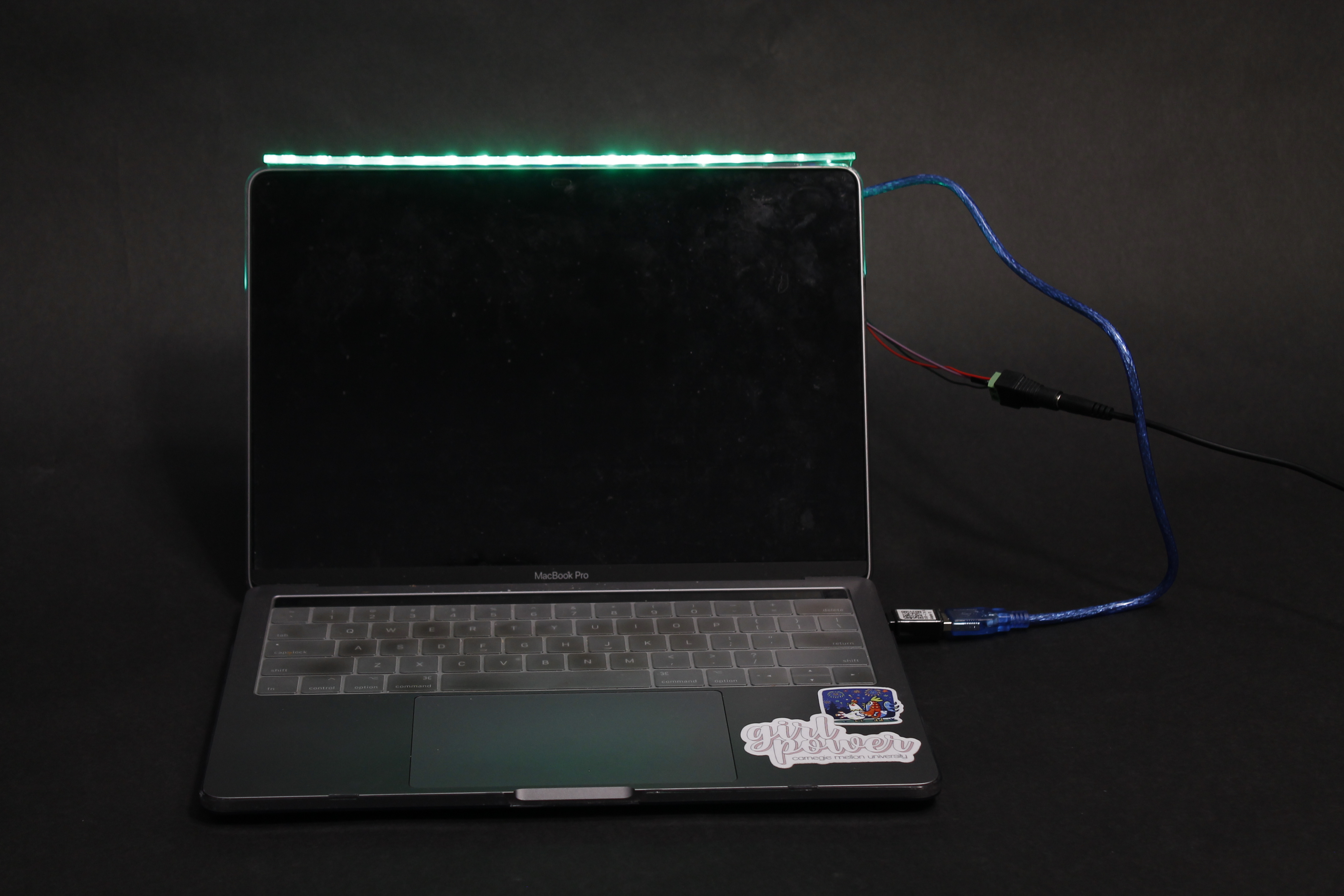
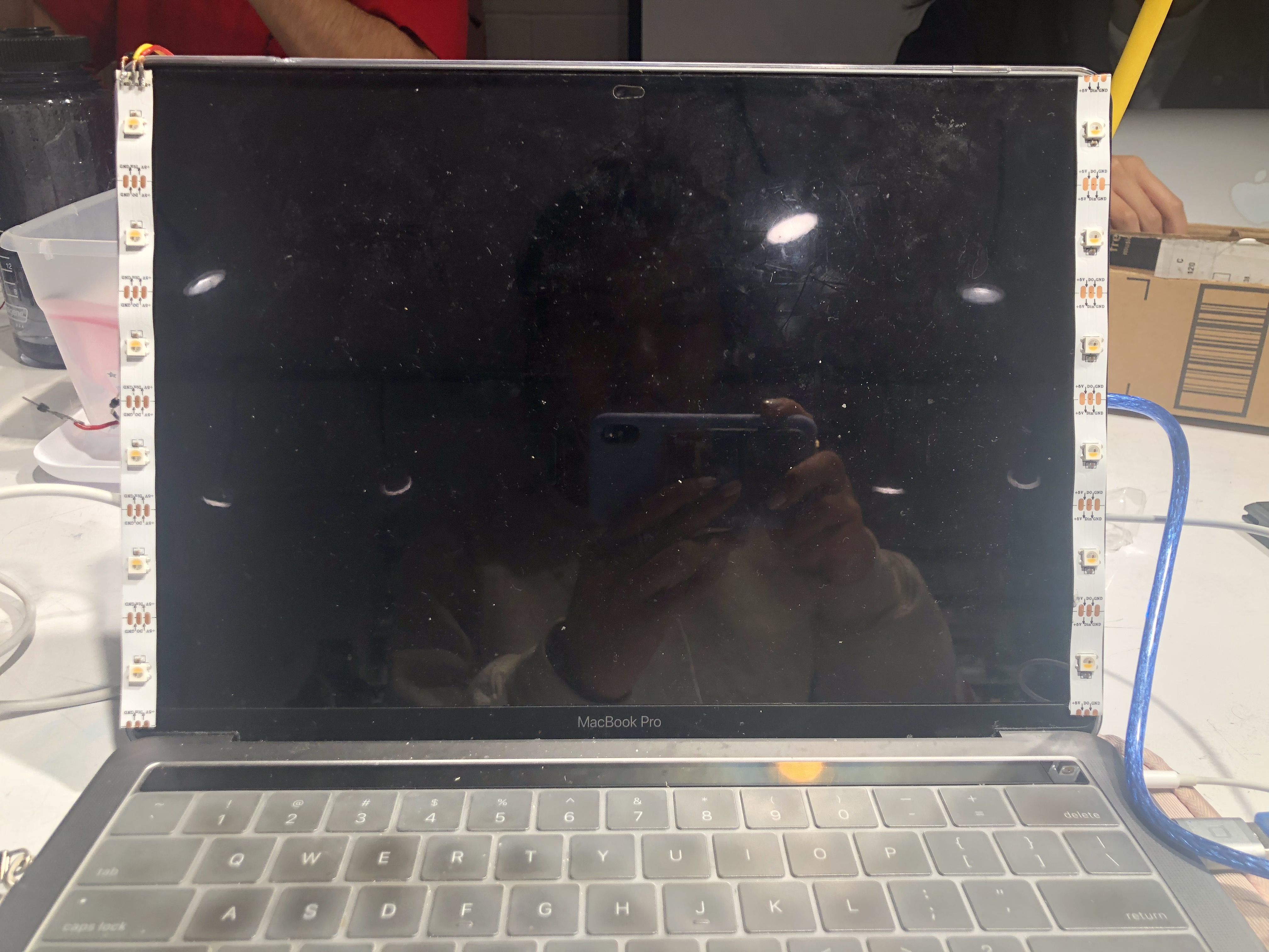
Front view of the light.
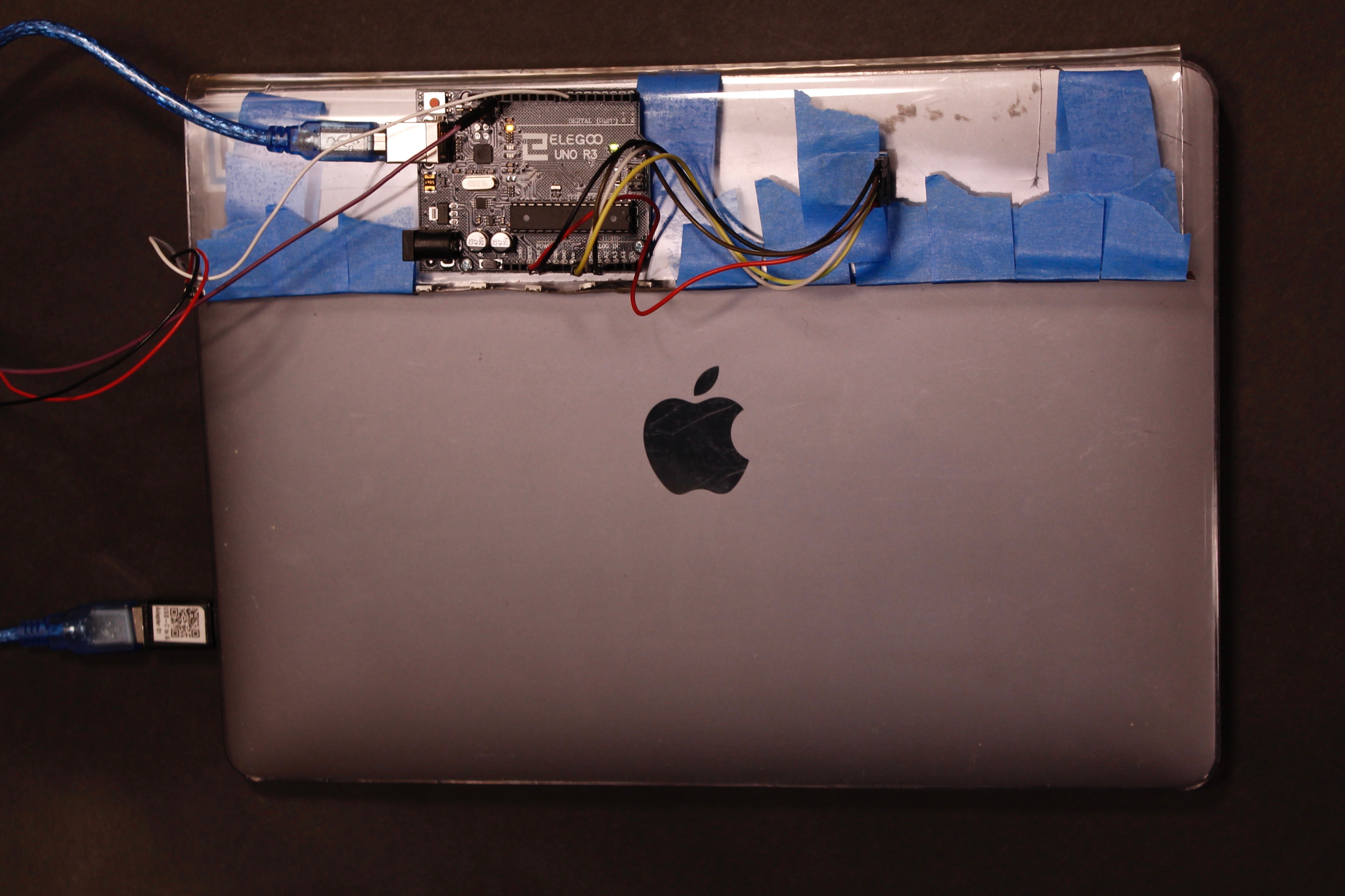
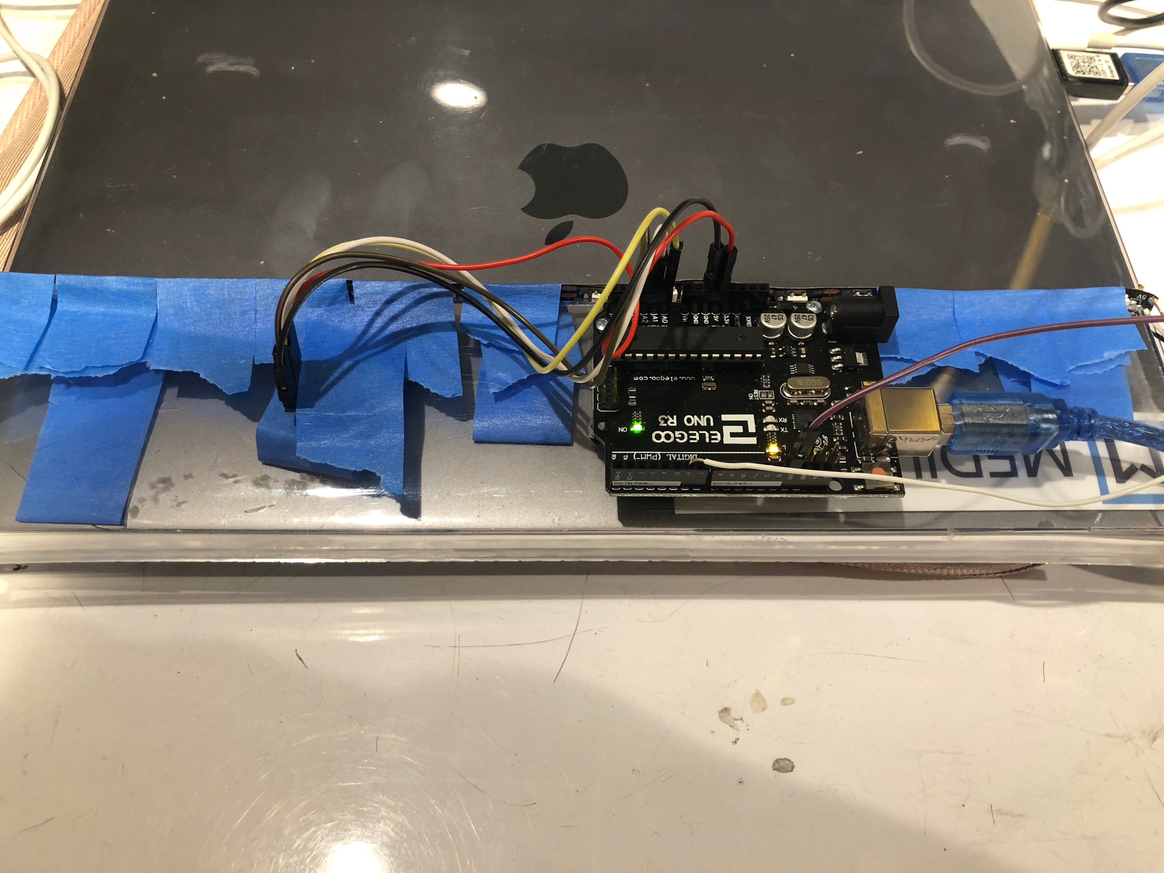
The hardware of the project–Arduino and accelerometer screwed into the acrylic band.
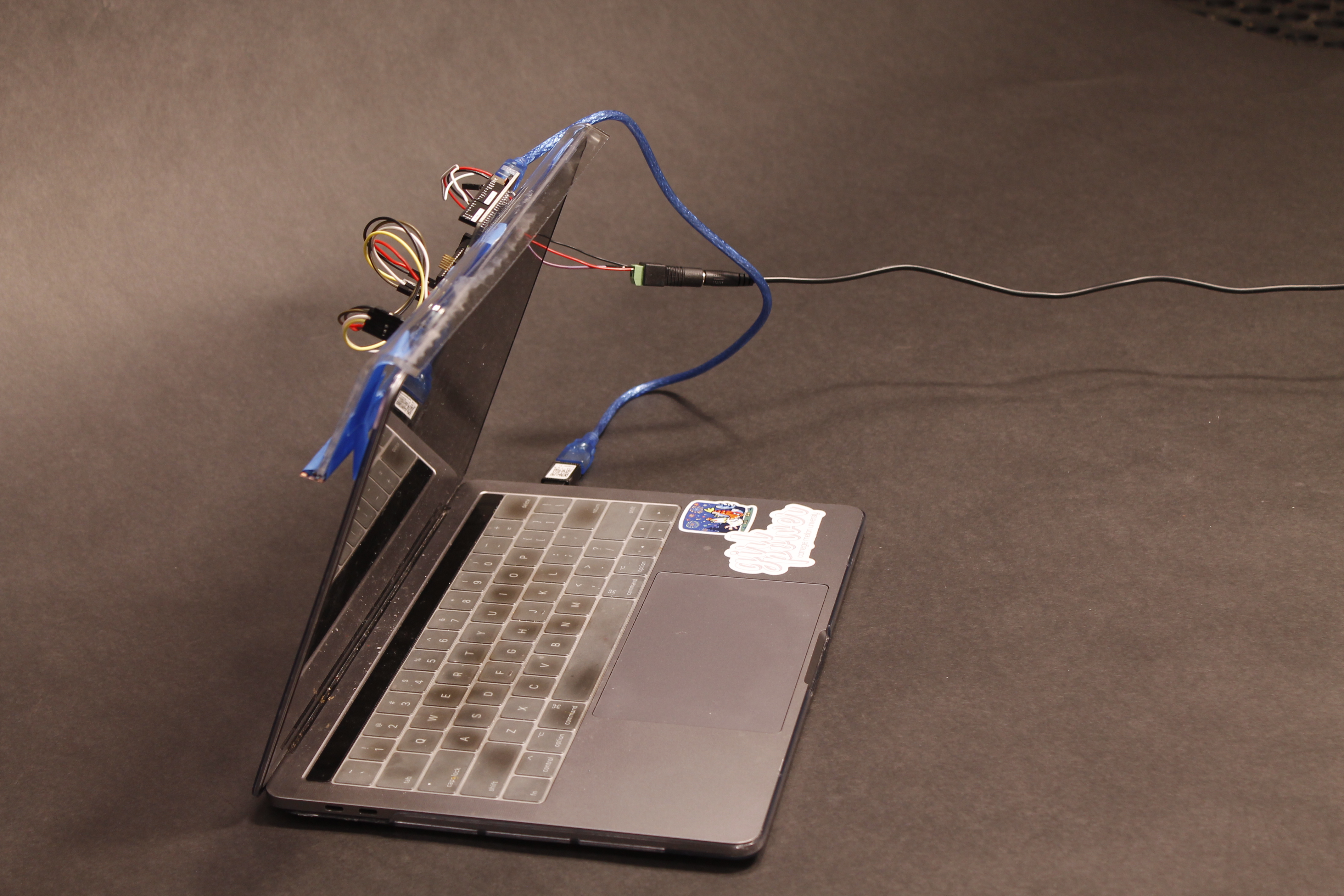
Side view of the project.
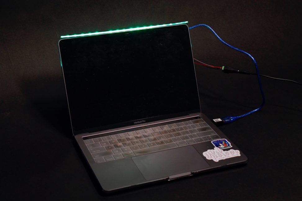
Example of use.
Process images and review
One of the hardest decisions I had to make was how to display the light in a way that was not distracting and was seamlessly integrated into the product. I had a few ideas for this, such as having the light strip on the sides of the laptop or have the light pop out either through a motor or having the user physically pull the lights out after every use. However, the first idea would not allow the laptop to close and the second idea was interfering with the user’s interaction of the actual laptop. Thus, having light emitted from the top of the laptop through a waveguide was the best way to display light while also maintaining normal interaction with a laptop and allowed the design to be integrated into the design of the case without much interference.
One of the initial ideas for how light is displayed, however this gets in the way of the functionality of the laptop when closing.
A second challenge was to decide the light pattern that would not distract the user, yet still effectively alerts the user to look away. I played around with the whole rainbow– which would have gone from red to orange to green to blue to green to orange and back to red. However, this didn’t make sense because the light patterns repeat. Thus, I decided to do half the rainbow, from blue to red. I chose blue to be first because red was more of an attention-grabbing color. This was still challenging to decide because blue light tires the eyes as well, making both colors have drawbacks as the initial light color. However, after testing this range from blue to red on my own eyes I decided that it was more important to have the end color be attention-grabbing.
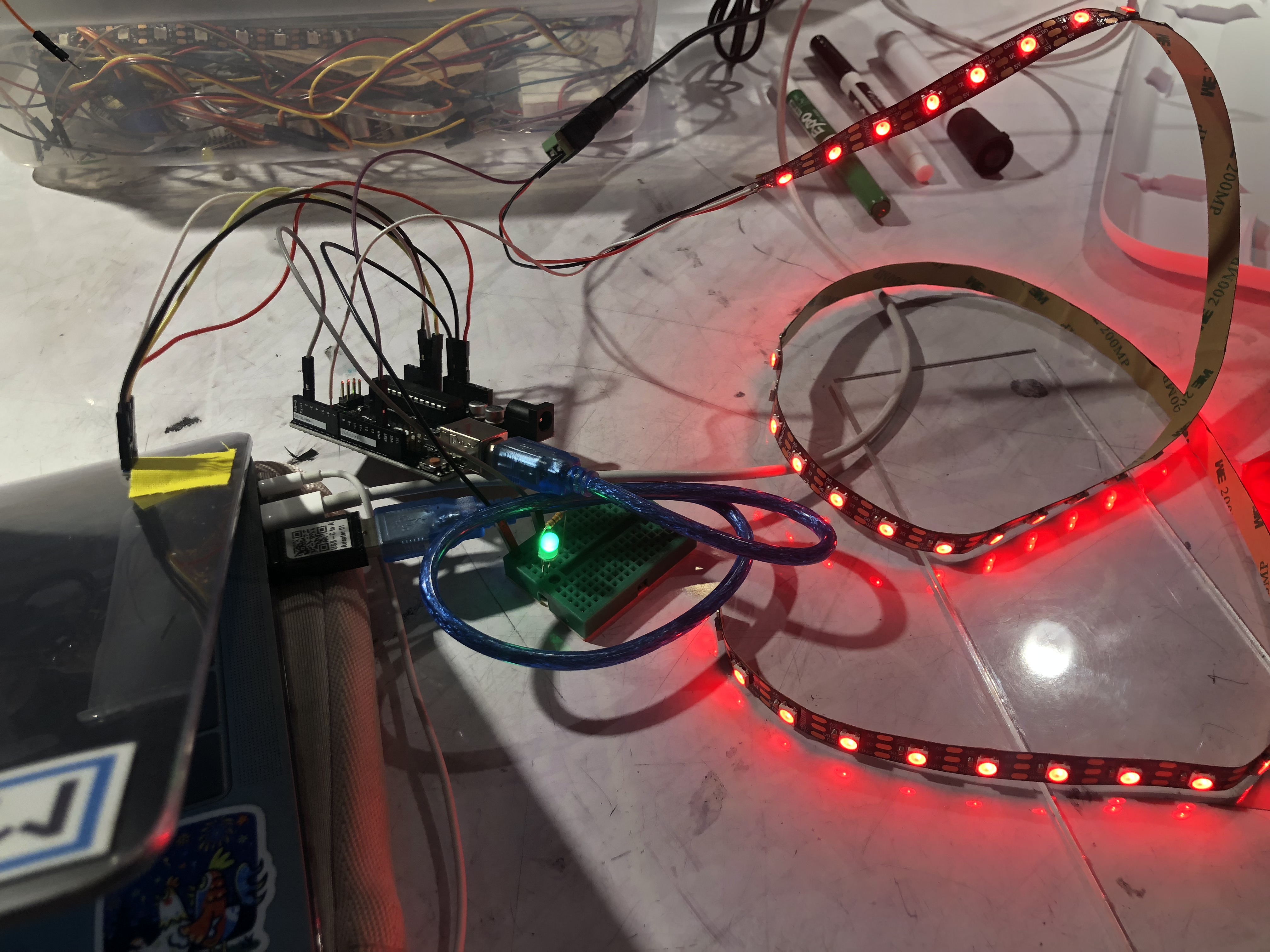
Red light working on the LED strip.
Draft of the waveguide, without securing the accelerometer and Arduino into the acrylic.
Discussion
Response to Critique
“Ending with red light definitely gives an alarming feel. What if yours started from a soothing light and it would slowly turn to red? (Or dim red/pink -> bright red) Because there are blue light filters because blue lights tire your eyes. Having lights at the other end of the acrylic is so cool. It’s like you made a light cable but in a curved plane.”
I agree that the range of lights is alarming and bright. The whole point of the shape of this project was to keep the device subtle and non-evasive, however, the lights are striking to the eye. I think a good way to fix this would be to change the range of lights and dim it down. The lights don’t have to iterate through the entire color spectrum, instead, it could range from a specific and more friendly set of colors.
“Front facing aesthetics are great! A simple line of light. Perhaps think about what people can change about the color(RGB, brightness, etc). Definitely consider how to mount it to any possible laptop. Think about an adjusting timer via hardware.”
I think that this is a good idea for personalization! I think that being able to change the range of color and the brightness of the light will definitely add to the project. Also, an adjusting timer is a good idea for when people want to focus on different amounts of time. For example, if I had an assignment due soon I would adjust the timer for it to be a longer period of focus, whereas if I am just watching Netflix the timer could be shorter to prevent eyestrain.
“The lights are a bit bright–somehow covering them would help (instead of clear acrylic, white? fewer LEDs? Maybe think of a way to improve the aesthetic on the back? So that the laptop can close comfortably without looking or feeling odd. Case idea sounded cool. “
I think the case idea is a good way to integrate the project into a product. Had the Arduino and accelerometer been embedded into a case, then the back hardware would be seamless and there would be no wires and blue tape. This would improve the aesthetics and the ease of use of the product. I also agree that the lights are bright, tying in with the previous critique, the brightness of the light could be adjustable.
Self-critique of Project
I am happy with how the project turned out. I wanted a device that would allow me to see how long I was using my laptop screen in a subtle way that did not interfere with how I used my laptop and this project accomplishes that. I did end up using my project in class and I found myself catching when the light turned red and looking away from my screen for a few minutes. I think had the hardware been integrated into a fitting laptop case, I would use this project in my day to day life.
What I Learned
Taking in the critique from Project 1, I wanted to incorporate a better presentation for this project. With this in mind and clear acrylic’s light-bending property, I decided to learn more about how to use this versatile material. I learned some basics of laser cutting through the people who manned the laser cutting lab including how to create the shape, transferring the shape file to a physical plastic cutout, and how to process the acrylic afterward to reduce burning. After having the cut of acrylic, I learned how to manipulate my cut shape to best fit my project. I used a heat gun and clamp to bend the rectangular plastic into an “L” shape. I also learned how to create a waveguide, which was an essential part of this project. After numerous attempts at creating the optimal way to incorporate the light, I found that I had to think outside of the box to achieve my goal.
In the next iteration of this project, I would take the advice from my critique to add more user controls such as light pattern and the timer. This would be much better because everyone’s attention span is different and are sensitive to different types of light. This would also allow the user to experiment with what kind of timing or light pattern works best for them, making the device more personalized. Also, I would have made the prototype more production ready and embed the Arduino and Accelerometer more securely into the acrylic without free wires on the back. Instead of an attachment, I could integrate the Arduino and the light into a laptop case instead of having it as an attachment. This would encourage use because it would be a much more seamless and durable design.
Technical information
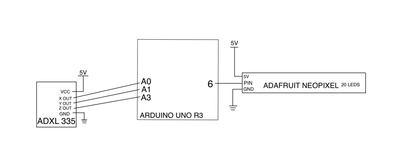
Schematic for Light Extension
/*
 * Laptop Light Extension
 * Jenny Han (jennyh1)
 *
 * Based on the angle that the accelerometer, the code determines whether or
 * not the laptop is at an angle that the user is looking at the screen.
 * If the user is not, then the light turns off and the program resets.
 * If the user is, then the program runs code to change the light pattern
 * of the LED strip over the course of a set time.
 *
 * Referenced from ADAFruit NeoPixel example "buttoncycler"
 * Referenced from https://github.com/infomaniac50/ADXL335/blob/master/examples/ADXL335_Demo/ADXL335_Demo.pde
 */

#include <ADXL335.h>
#include <Adafruit_NeoPixel.h>
#ifdef __AVR__
  #include <avr/power.h>
#endif

#define PIN 6
unsigned long timer = 0;


Adafruit_NeoPixel strip = Adafruit_NeoPixel(60, PIN, NEO_GRB + NEO_KHZ800);

//pins for the ADXL chip
const int pin_x = A0;
const int pin_y = A1;
const int pin_z = A2;
const float aref = 3.3;
int counter = 127;

ADXL335 accel(pin_x, pin_y, pin_z, aref);

void setup()
{

  #if defined (__AVR_ATtiny85__)
    if (F_CPU == 16000000) clock_prescale_set(clock_div_1);
  #endif

  Serial.begin(9600);
  //prints out the angles that the ADXL senses
  Serial.println("X,\tY,\tZ,\tRho,\tPhi,\tTheta");
  strip.begin();
  strip.show();
  rainbow2(1,counter);
}

void loop()
{
  //this is required to update the values
  accel.update();

  //this tells us how long the string is
  int string_width;

  float x;
  float y;
  float z;

  //for these variables see wikipedia's
  //definition of spherical coordinates
  float rho;
  float phi;
  float theta;

  x = accel.getX();
  y = accel.getY();
  //if the project is laying flat and top up the z axis reads ~1G
  z = accel.getZ();
  rho = accel.getRho();
  phi = accel.getPhi();
  theta = accel.getTheta();
  //prints out different position angles
  Serial.print(formatFloat(x, 2, &string_width));
  Serial.print(",\t");
  Serial.print(formatFloat(y, 2, &string_width));
  Serial.print(",\t");
  Serial.print(formatFloat(z, 2, &string_width));
  Serial.print(",\t");

  Serial.print(formatFloat(rho, 2, &string_width));
  Serial.print(",\t");
  Serial.print(formatFloat(phi, 2, &string_width));
  Serial.print(",\t");
  Serial.print(formatFloat(theta, 2, &string_width));
  Serial.println("");

  //if vertical angle is less than 128, then the laptop is on
  if (theta<128 ){
    Serial.println("on!");
    if (millis() - timer >= 500 ){    // 30000 ~ 60 minutes
    // this happens once per second
      timer = millis();
      //run colors on LED Strip
      rainbow2(1,counter);
      Serial.println(counter);
      if(counter==0){
        Serial.println("keep");
      } else {
        counter--;
      }

    }

  } else {
    //turn it off
    Serial.println("off!");
    counter = 127;
    colorWipe(strip.Color(0, 0, 0), 10);    // Black/off

  }
  delay(1000);
}
//run color pattern, a rainbow strip
void rainbow2(uint8_t wait,int j2) {
   uint16_t i;
    //set color for every led in strip
    for(i=0; i<strip.numPixels(); i++) {
      //strip.setPixelColor(i, Wheel((i+j) & 255));
      strip.setPixelColor(i, Wheel((j2) & 255));
      delay(wait);
    }
    strip.show();
    delay(wait);
}
//removes color when turned off
void colorWipe(uint32_t c, uint8_t wait) {
  for(uint16_t i=0; i<strip.numPixels(); i++) {
    strip.setPixelColor(i, c);
    strip.show();
    delay(wait);
  }
}
//helper function to set color of strip
uint32_t Wheel(byte WheelPos) {
  WheelPos = 255 - WheelPos;
  if(WheelPos < 85) {
    return strip.Color(255 - WheelPos * 3, 0, WheelPos * 3);
  }
  if(WheelPos < 170) {
    WheelPos -= 85;
    return strip.Color(0, WheelPos * 3, 255 - WheelPos * 3);
  }
  WheelPos -= 170;
  return strip.Color(WheelPos * 3, 255 - WheelPos * 3, 0);
}

//this function was taken from my format float library
//used to make the angles taken from the ADXL human readable
String formatFloat(double value, int places, int* string_width)
{
  //if value is positive infinity
  if (isinf(value) > 0)
  {
    return "+Inf";
  }

  //Arduino does not seem to have negative infinity
  //keeping this code block for reference
  //if value is negative infinity
  if(isinf(value) < 0)
  {
    return "-Inf";
  }

  //if value is not a number
  if(isnan(value) > 0)
  {
    return "NaN";
  }

  //always include a space for the dot
  int num_width = 1;

  //if the number of decimal places is less than 1
  if (places < 1)
  {
    //set places to 1
    places = 1;

    //and truncate the value
    value = (float)((int)value);
  }

  //add the places to the right of the decimal
  num_width += places;

  //if the value does not contain an integral part
  if (value < 1.0 && value > -1.0)
  {
    //add one for the integral zero
    num_width++;
  }
  else
  {

    //get the integral part and
    //get the number of places to the left of decimal
    num_width += ((int)log10(abs(value))) + 1;
  }
  //if the value in less than 0
  if (value < 0.0)
  {
    //add a space for the minus sign
    num_width++;
  }

  //make a string the size of the number
  //plus 1 for string terminator
  char s[num_width + 1];

  //put the string terminator at the end
  s[num_width] = '\0';


  //initalize the array to all zeros
  for (int i = 0; i < num_width; i++)
  {
    s[i] = '0';
  }

  //characters that are not changed by
  //the function below will be zeros

  //set the out variable string width
  //lets the caller know what we came up with
  *string_width = num_width;

  //use the avr-libc function dtosrtf to format the value
  return String(dtostrf(value,num_width,places,s));
}
Leave a Reply
You must be logged in to post a comment.