Title: Double Transducer: Vibration to Color
Description:
This project senses the frequency of a vibration, which turns a stepper motor a number of steps, which turns a potentiometer, whose value determines the angle that a color wheel spins to.
Progress:
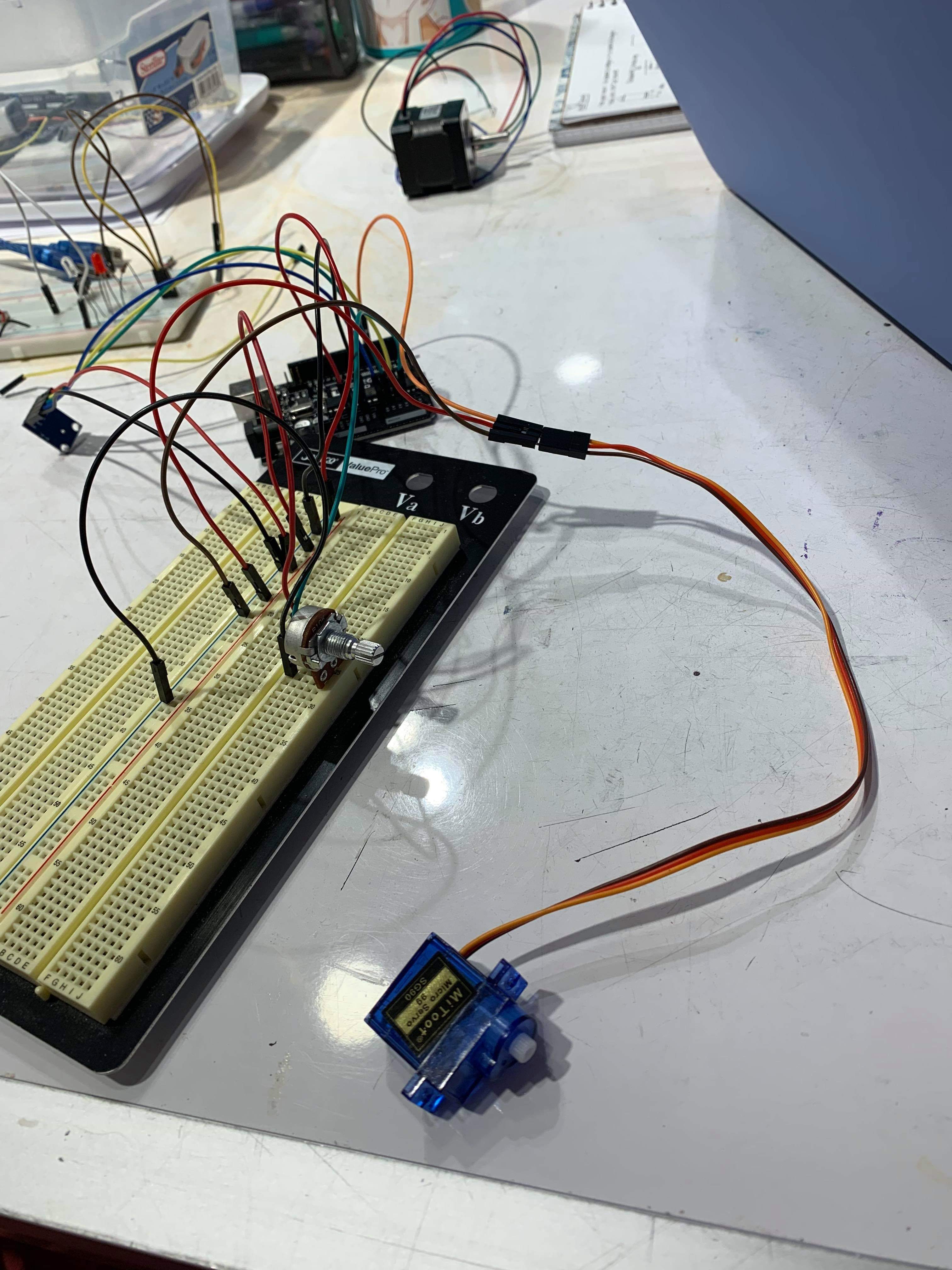
Hooking up servo, accelerometer, and potentiometer connections
Building a stand to hold accelerometer in constant vertical g field along Z axis
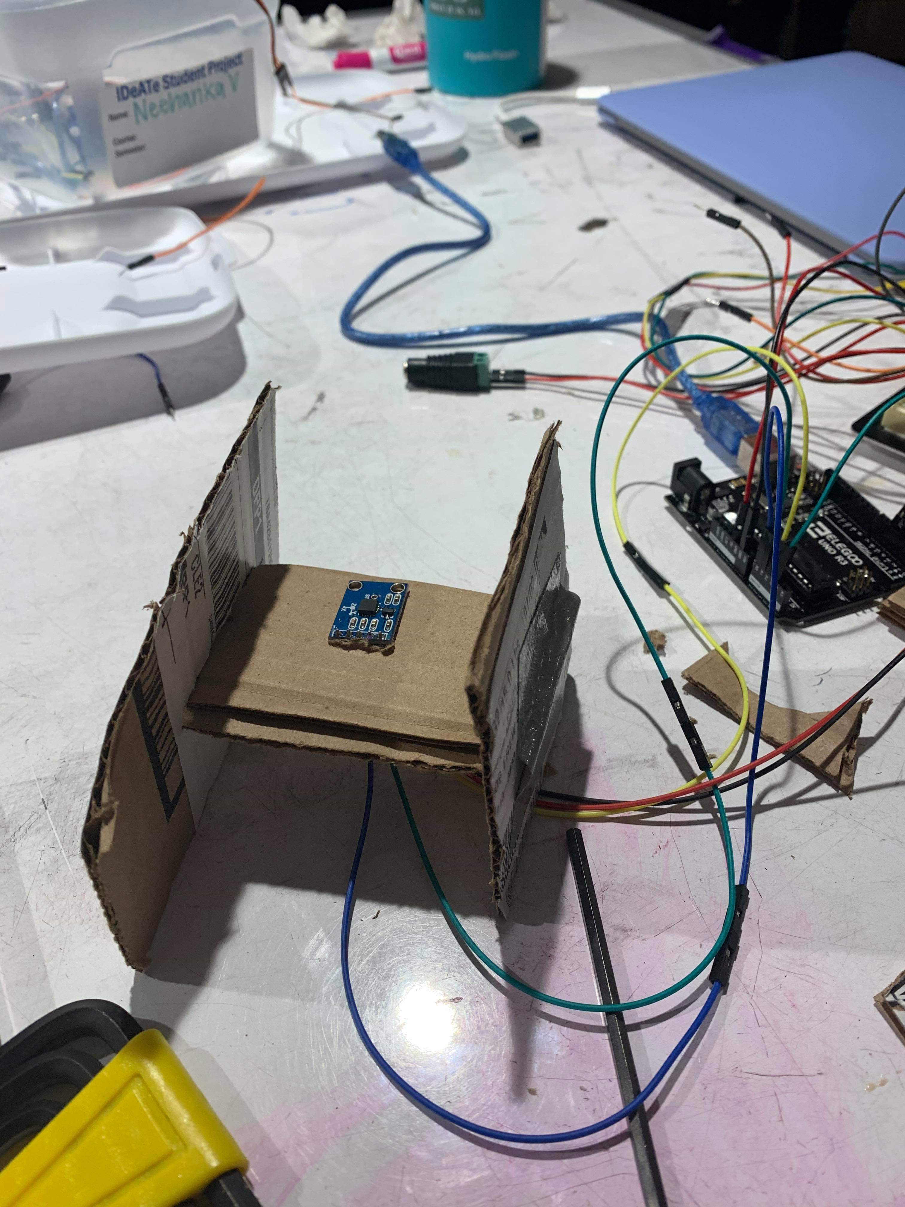
Building a stand to hold accelerometer in constant vertical g field along Z axis
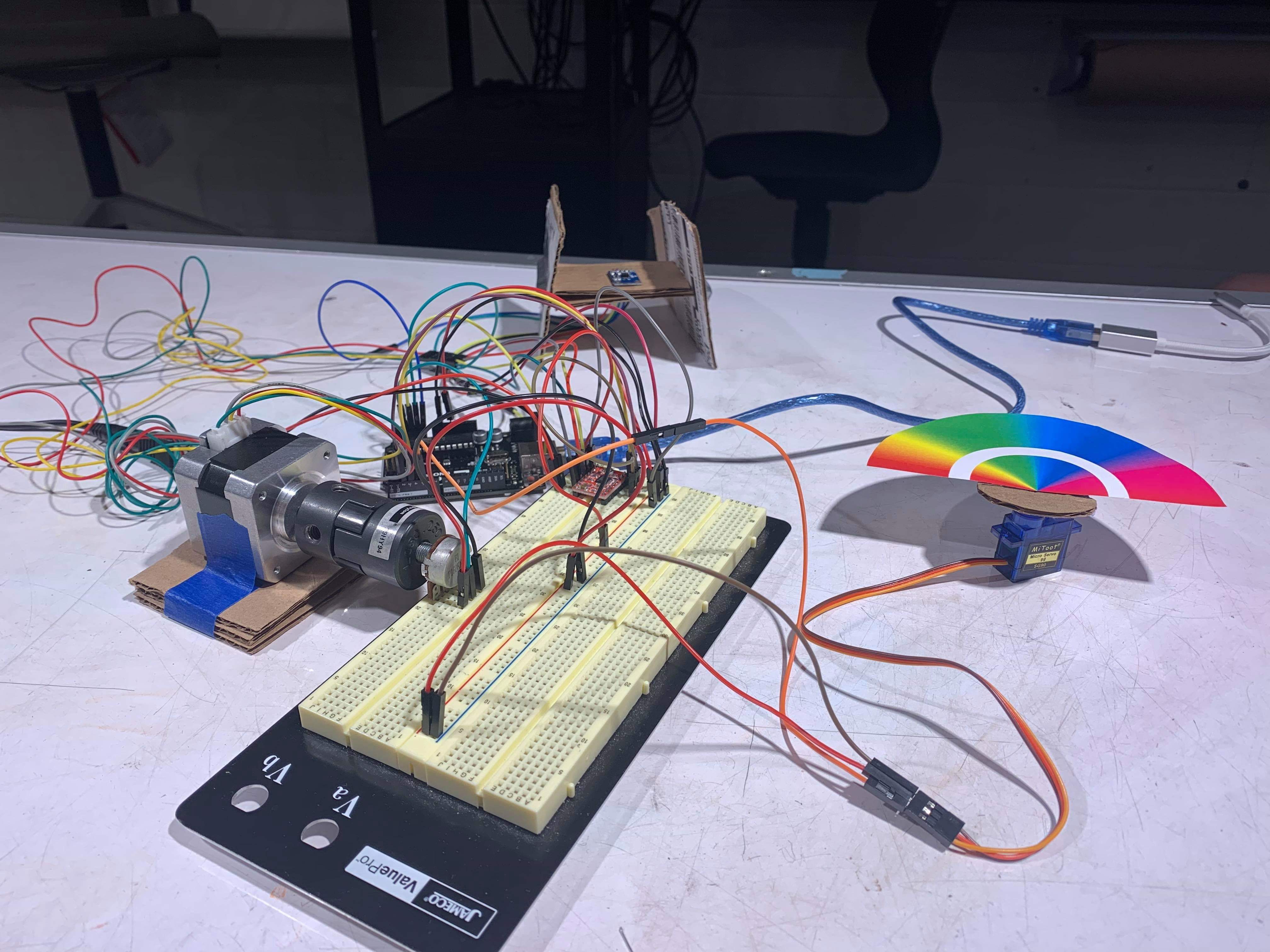
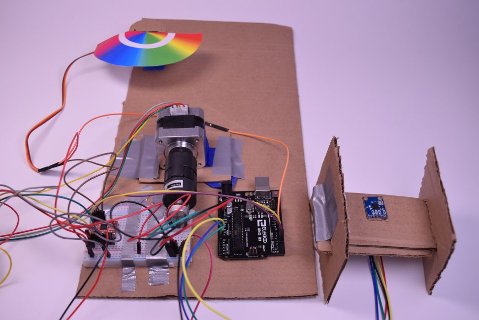
First prototype with all components connected and interacting with one another. A shaft coupler was used to connect the potentiometer with the stepper motor.
Discussion:
There were a number of challenges in getting the accelerometer, stepper motor, and potentiometer to all work together cohesively.
Our initial idea in order to measure the amount of vibration was to average the x-axis, y-axis, and z-axis values from the accelerometer at each point in time. Then, compare those averages to each other to register a “vibration”. However, we realized on initial collection of these values that movement in each axis was counteracting the movement in the other axes, resulting in relatively stagnant average values. We decided to only focus on one axis to track rather than all of them, and thought that the vibration would probably happen mostly up and down. Therefore, we settled on tracking the z-axis. But we still needed to figure out how to register that a vibration occurred.
Initially, we had assumed the input from the vibration motor would come with variable magnitude. With further research, however, we realized that the vibration motor would vary it’s frequency proportionally to its input voltage. This posed the tricky problem of figuring out how to register the frequency of the input analog signal without more complex DSP hardware and software. Our solution was relatively simple and easily adjustable based on the performance we observed. We decided to fix our accelerometer with its z-axis experiencing a constant acceleration of one g. We would then decide on a suitable bias to subtract from the z-input readings and then ‘sample’ the incoming analog signal for a short period of time in our loop() function. Each time the signal was observed to cross a customizable threshold, we would increment a counter and treat this counter as a rough measurement of frequency.
The results from this method were relatively encouraging with the whole system behaving generally as we would expect it to. It would have been helpful however to actually stimulate the accelerometer with a vibration motor rather than our hands to allow us to more accurately provide input frequency with a wider range.
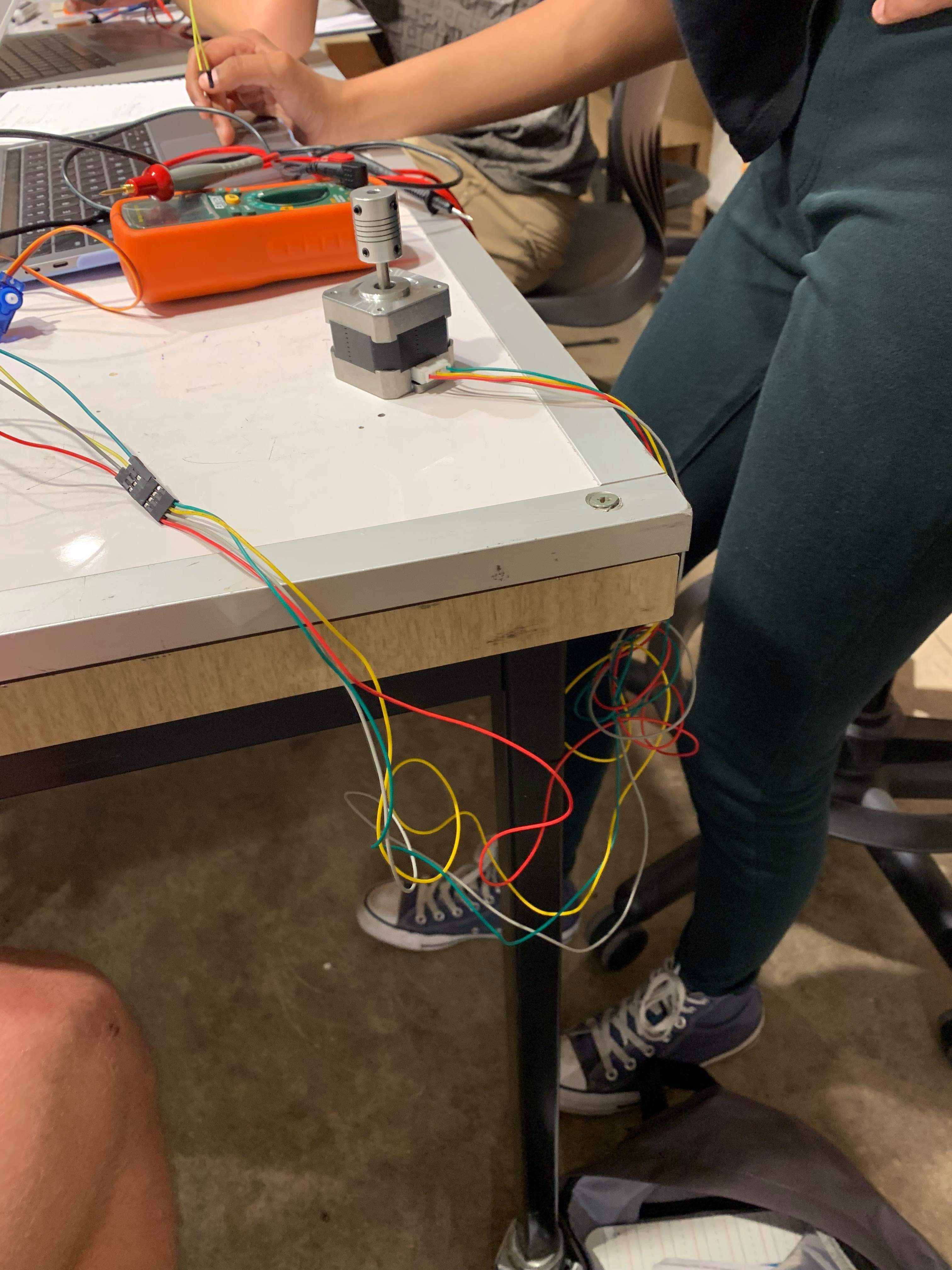
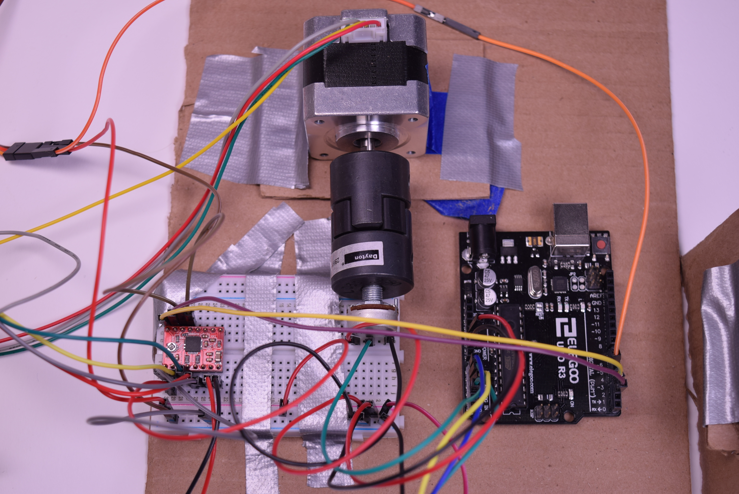
We had some issues attaching the stepper motor to the potentiometer in the first place. We first primitively tried it with masking tape, and then when that didn’t work, duct tape. In both cases, the axis of the stepper motor merely shifted itself under the tape without moving the potentiometer at all. We ended up using shaft couplers we found in the lab to do the job, which worked well. However, there were still certain things we needed to take care of in order for the stepper motor and potentiometer to function together.
We also realized that during the set-up part of the code execution, the stepper motor would jitter for a while before resting at the 0 position. If it was already attached to the potentiometer, it could possibly lift it out of its place. This means that during set-up the stepper would have to remain detached from the potentiometer, and then connected after. We resolved this by leaving a small delay after the set-up code, in which it was understood that we would quickly attach the stepper to the potentiometer after the jitter in that timeframe. Not the most elegant solution, but we were unclear as to why the stepper was moving around in the first place.
One of our unsolved issues and a place in which our machine could have used improvement was debugging and removing some of the noise which seemed to cause the stepper motor to rotate or jitter at unexpected times. Some of the places we suspect it could have been coming from includes some vibrational feedback from the motor to the accelerometer, loose connections at the pins of the potentiometer, or perhaps incorrectly assuming that the stepper motor “zeroed” its relative position on startup.
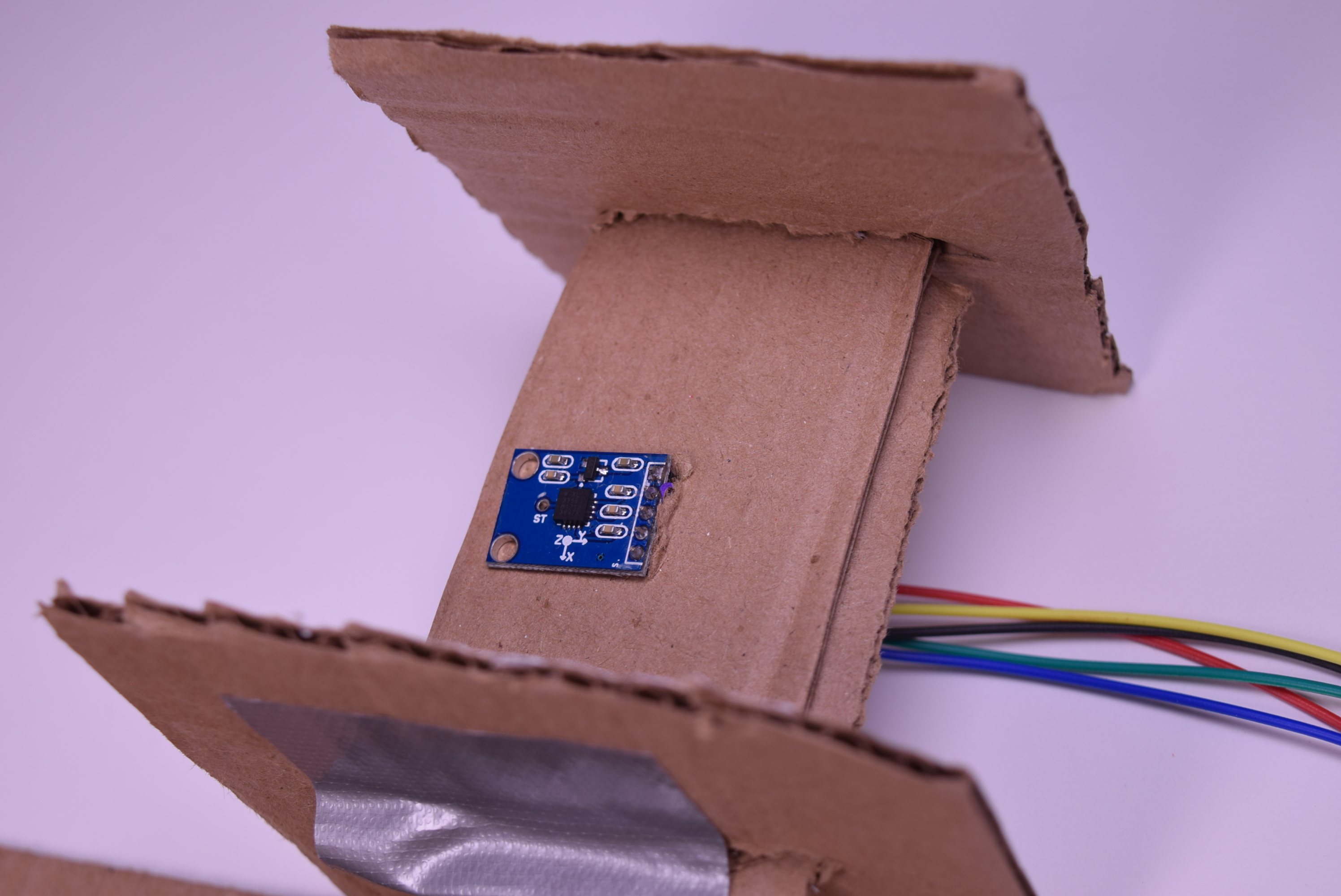
The accelerometer is mounted to help isolate it from outside vibrations.
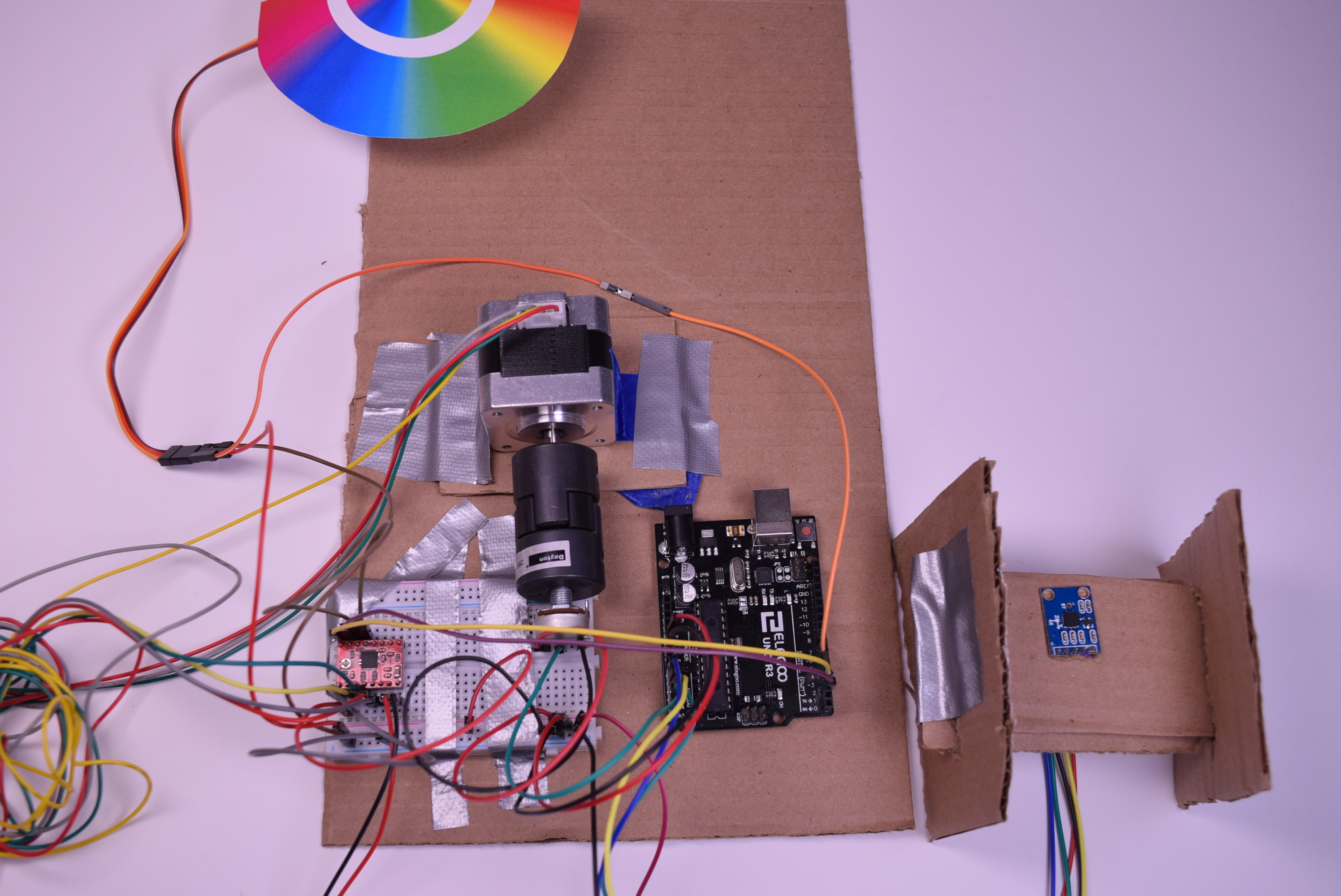
An Overview of the Layout
Wire management would need to be improved on later iterations to cut down on clutter.
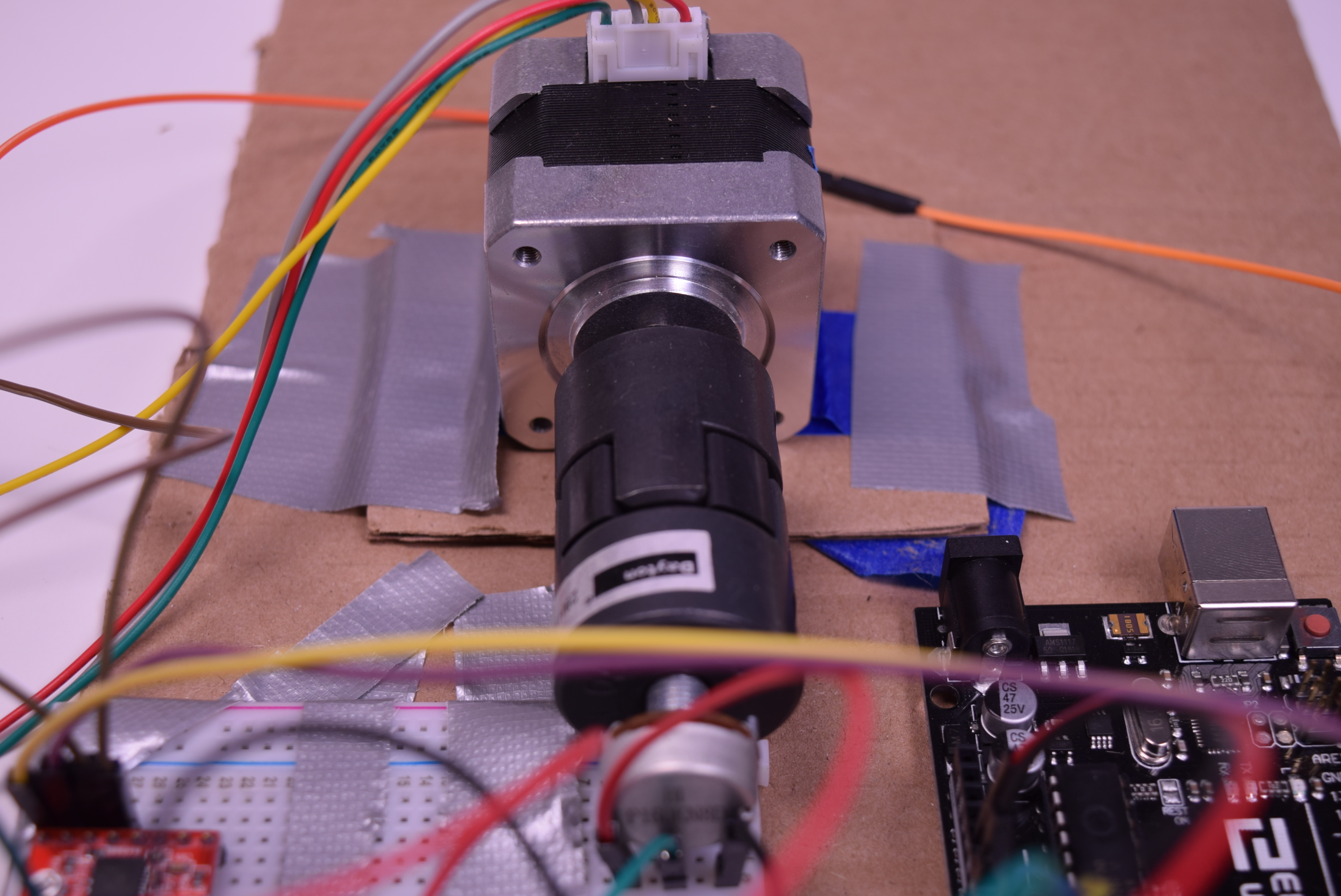
Shaft couplers were used to attach the different motors together.

A servo turns 180 degrees to allow a stationary color reader to sense different wavelengths.
The accelerometer roughly measures the frequency of input vibrations to the accelerometer. This turns the stepper which allows the potentiometer to re-encode the rotation into the rotational displacement of the servo and color wheel.
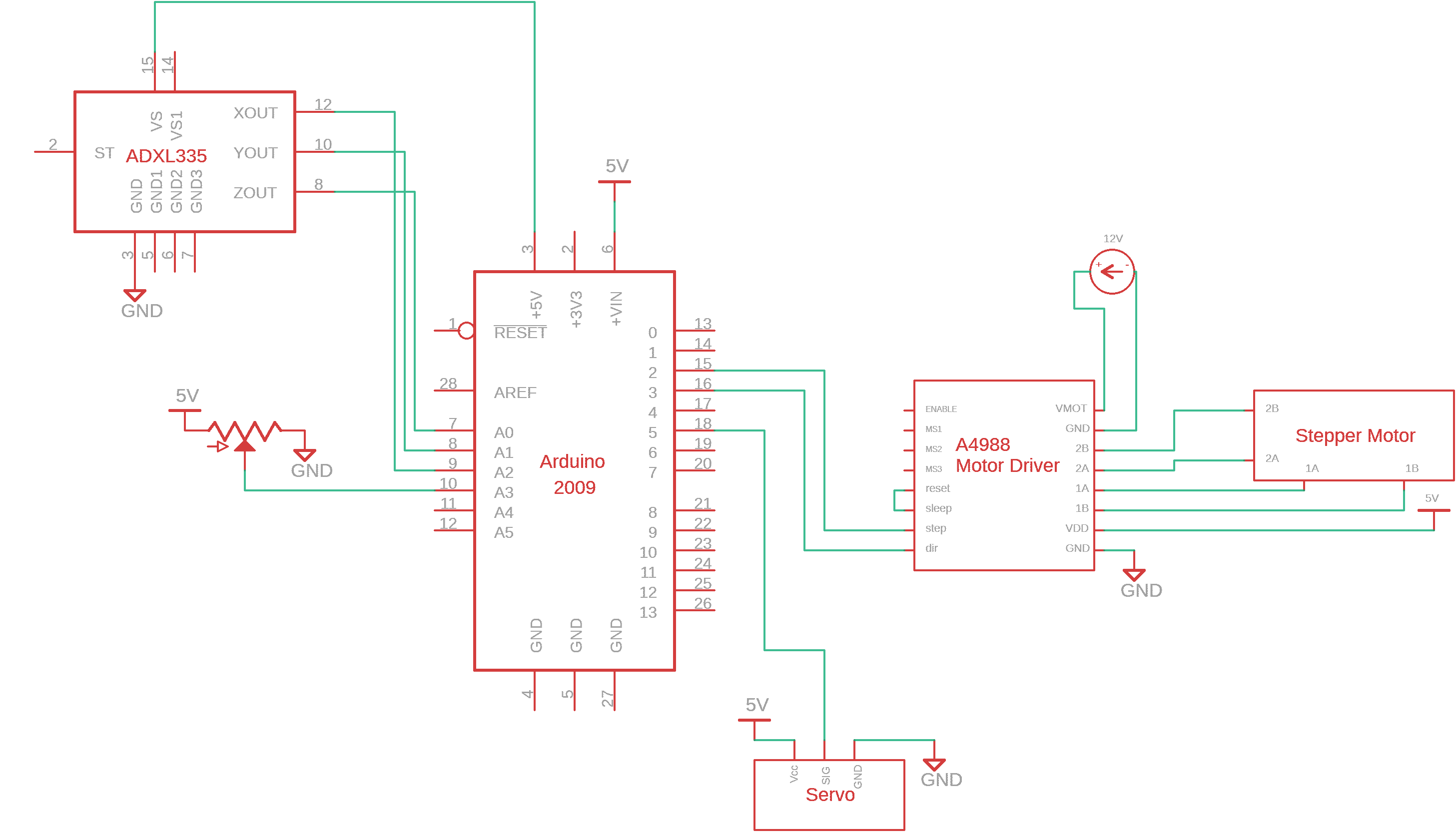
Schematic:
Code:
- <span class="com">/*
- * Project 1 (Vibration -> Color)
- * Neeharika Vogety (nvogety) and Nicholas Toldalagi(ntoldala)
- * ~4 hours
- *
- * Collaboration: Code was written together. Portions of Servo and Stepper Motor
- * code was taken from starter code provided in the Tutorials section of the 60-223
- * webpage.
- *
- * Next time: In other projects, we will start much earlier and plan ahead before
- * starting.
- *
- * Summary: Vibration(changes in z axis from accelerometer) -> Turn Stepper
- * Motor -> Turn Potentiometer -> Move Servo Motor(on which a color wheel
- * is attached)
- *
- * Inputs:
- * Arduino pin | input
- * A2 X Axis Accelerometer
- * A1 Y Axis Accelerometer
- * A0 Z Axis Accelerometer
- * A3 Potentiometer
- *
- * Outputs:
- * Arduino pin | output
- * 2 Stepper Motor Driver Step Pin
- * 3 Stepper Motor Driver Direction Pin
- * 5 Servo Motor Pin
- */</span><span class="pln">
- </span><span class="com">#include</span><span class="pln"> </span><span class="str"><AccelStepper.h></span><span class="pln">
- </span><span class="com">#include</span><span class="pln"> </span><span class="str"><Servo.h></span><span class="pln">
- </span><span class="com">//</span><span class="pln">
- </span><span class="kwd">const</span><span class="pln"> </span><span class="kwd">int</span><span class="pln"> X_PIN </span><span class="pun">=</span><span class="pln"> A2</span><span class="pun">;</span><span class="pln">
- </span><span class="kwd">const</span><span class="pln"> </span><span class="kwd">int</span><span class="pln"> Y_PIN </span><span class="pun">=</span><span class="pln"> A1</span><span class="pun">;</span><span class="pln">
- </span><span class="kwd">const</span><span class="pln"> </span><span class="kwd">int</span><span class="pln"> Z_PIN </span><span class="pun">=</span><span class="pln"> A0</span><span class="pun">;</span><span class="pln">
- </span><span class="kwd">const</span><span class="pln"> </span><span class="kwd">int</span><span class="pln"> POT_PIN </span><span class="pun">=</span><span class="pln"> A3</span><span class="pun">;</span><span class="pln">
- </span><span class="kwd">const</span><span class="pln"> </span><span class="kwd">int</span><span class="pln"> STEP_PIN </span><span class="pun">=</span><span class="pln"> </span><span class="lit">2</span><span class="pun">;</span><span class="pln">
- </span><span class="kwd">const</span><span class="pln"> </span><span class="kwd">int</span><span class="pln"> DIR_PIN </span><span class="pun">=</span><span class="pln"> </span><span class="lit">3</span><span class="pun">;</span><span class="pln">
- </span><span class="kwd">const</span><span class="pln"> </span><span class="kwd">int</span><span class="pln"> SERV_PIN </span><span class="pun">=</span><span class="pln"> </span><span class="lit">5</span><span class="pun">;</span><span class="pln">
- </span><span class="com">// Create AccelStepper and Servo objects</span><span class="pln">
- </span><span class="typ">AccelStepper</span><span class="pln"> myMotor</span><span class="pun">(</span><span class="lit">1</span><span class="pun">,</span><span class="pln"> STEP_PIN</span><span class="pun">,</span><span class="pln"> DIR_PIN</span><span class="pun">);</span><span class="pln">
- </span><span class="typ">Servo</span><span class="pln"> s1</span><span class="pun">;</span><span class="pln">
- </span><span class="kwd">void</span><span class="pln"> setup</span><span class="pun">(){</span><span class="pln">
- </span><span class="typ">Serial</span><span class="pun">.</span><span class="kwd">begin</span><span class="pun">(</span><span class="lit">9600</span><span class="pun">);</span><span class="pln">
- </span><span class="com">// Set up pins</span><span class="pln">
- pinMode</span><span class="pun">(</span><span class="pln">X_PIN</span><span class="pun">,</span><span class="pln"> INPUT</span><span class="pun">);</span><span class="pln">
- pinMode</span><span class="pun">(</span><span class="pln">Y_PIN</span><span class="pun">,</span><span class="pln"> INPUT</span><span class="pun">);</span><span class="pln">
- pinMode</span><span class="pun">(</span><span class="pln">Z_PIN</span><span class="pun">,</span><span class="pln"> INPUT</span><span class="pun">);</span><span class="pln">
- pinMode</span><span class="pun">(</span><span class="pln">POT_PIN</span><span class="pun">,</span><span class="pln"> INPUT</span><span class="pun">);</span><span class="pln">
- </span><span class="com">// Set up servo with pin</span><span class="pln">
- s1</span><span class="pun">.</span><span class="pln">attach</span><span class="pun">(</span><span class="pln">SERV_PIN</span><span class="pun">);</span><span class="pln">
- </span><span class="com">// Set up stepper motor </span><span class="pln">
- myMotor</span><span class="pun">.</span><span class="pln">setMaxSpeed</span><span class="pun">(</span><span class="lit">200</span><span class="pun">);</span><span class="pln">
- myMotor</span><span class="pun">.</span><span class="pln">setAcceleration</span><span class="pun">(</span><span class="lit">100</span><span class="pun">);</span><span class="pln">
- </span><span class="com">// Set stepper motor to move to position 0</span><span class="pln">
- myMotor</span><span class="pun">.</span><span class="pln">moveTo</span><span class="pun">(</span><span class="lit">0</span><span class="pun">);</span><span class="pln">
- </span><span class="com">// Move stepper motor to position 0</span><span class="pln">
- </span><span class="kwd">while</span><span class="pln"> </span><span class="pun">(</span><span class="pln">myMotor</span><span class="pun">.</span><span class="pln">distanceToGo</span><span class="pun">()</span><span class="pln"> </span><span class="pun">!=</span><span class="pln"> </span><span class="lit">0</span><span class="pun">)</span><span class="pln"> </span><span class="pun">{</span><span class="pln"> </span><span class="com">// while there is still a distance to go,</span><span class="pln">
- myMotor</span><span class="pun">.</span><span class="pln">run</span><span class="pun">();</span><span class="pln"> </span><span class="com">// make the motor run</span><span class="pln">
- </span><span class="pun">}</span><span class="pln">
- </span><span class="com">/* Because it has to wiggle around a little to find that 0th position, stepper
- * must start out dettached from potentiometer. Give about a 7 second delay
- * to attach stepper to potentiometer after 0th position is found.*/</span><span class="pln">
- delay</span><span class="pun">(</span><span class="lit">7000</span><span class="pun">);</span><span class="pln">
- </span><span class="pun">}</span><span class="pln">
- </span><span class="kwd">void</span><span class="pln"> loop</span><span class="pun">(){</span><span class="pln">
- </span><span class="com">// Set some important values</span><span class="pln">
- </span><span class="kwd">int</span><span class="pln"> threshold </span><span class="pun">=</span><span class="pln"> </span><span class="lit">10</span><span class="pun">;</span><span class="pln"> </span><span class="com">// How much above or below bias we want to register as a change in position</span><span class="pln">
- </span><span class="kwd">int</span><span class="pln"> bias </span><span class="pun">=</span><span class="pln"> </span><span class="lit">390</span><span class="pun">;</span><span class="pln"> </span><span class="com">// What a motionless accelerometer reads</span><span class="pln">
- </span><span class="kwd">int</span><span class="pln"> samplePeriod </span><span class="pun">=</span><span class="pln"> </span><span class="lit">1000</span><span class="pun">;</span><span class="pln"> </span><span class="com">// How many total samples to take</span><span class="pln">
- </span><span class="kwd">int</span><span class="pln"> maxFreq </span><span class="pun">=</span><span class="pln"> </span><span class="lit">100</span><span class="pun">;</span><span class="pln"> </span><span class="com">// Maximimum number of position changes registered - completely arbitrary</span><span class="pln">
- </span><span class="kwd">int</span><span class="pln"> minFreq </span><span class="pun">=</span><span class="pln"> </span><span class="lit">0</span><span class="pun">;</span><span class="pln"> </span><span class="com">// Min number of position changes registered - always 0</span><span class="pln">
- </span><span class="com">// Read accelerometer</span><span class="pln">
- </span><span class="kwd">int</span><span class="pln"> x_val </span><span class="pun">=</span><span class="pln"> analogRead</span><span class="pun">(</span><span class="pln">X_PIN</span><span class="pun">);</span><span class="pln">
- </span><span class="kwd">int</span><span class="pln"> y_val </span><span class="pun">=</span><span class="pln"> analogRead</span><span class="pun">(</span><span class="pln">Y_PIN</span><span class="pun">);</span><span class="pln">
- </span><span class="kwd">int</span><span class="pln"> z_val </span><span class="pun">=</span><span class="pln"> analogRead</span><span class="pun">(</span><span class="pln">Z_PIN</span><span class="pun">);</span><span class="pln">
- </span><span class="com">/* We want to calculate how many times the position of the accelerometer in the
- * z axis changes significantly. Specifically, we want the frequency.
- * We get this by sampling 1000 times, and within each sample registering
- * whether the recorded z position is above a certain large number or below a small number.
- * This large number and small number is calculated by either adding or subtracting a threshold
- * from the bias (see above int defs). The number of times this occurs is our frequency.
- */</span><span class="pln">
- </span><span class="typ">Serial</span><span class="pun">.</span><span class="pln">println</span><span class="pun">(</span><span class="str">"start z collection"</span><span class="pun">);</span><span class="pln">
- </span><span class="kwd">int</span><span class="pln"> sampleCounter </span><span class="pun">=</span><span class="pln"> </span><span class="lit">0</span><span class="pun">;</span><span class="pln">
- </span><span class="kwd">int</span><span class="pln"> zValCounter </span><span class="pun">=</span><span class="pln"> </span><span class="lit">0</span><span class="pun">;</span><span class="pln">
- </span><span class="kwd">int</span><span class="pln"> currzVal</span><span class="pun">;</span><span class="pln">
- </span><span class="kwd">while</span><span class="pun">(</span><span class="pln">sampleCounter </span><span class="pun"><</span><span class="pln"> samplePeriod</span><span class="pun">){</span><span class="pln">
- currzVal </span><span class="pun">=</span><span class="pln"> analogRead</span><span class="pun">(</span><span class="pln">Z_PIN</span><span class="pun">);</span><span class="pln">
- </span><span class="kwd">if</span><span class="pun">(</span><span class="pln">currzVal </span><span class="pun"><</span><span class="pln"> </span><span class="pun">(</span><span class="pln">bias </span><span class="pun">-</span><span class="pln"> threshold</span><span class="pun">)</span><span class="pln"> </span><span class="pun">||</span><span class="pln"> currzVal </span><span class="pun">></span><span class="pln"> </span><span class="pun">(</span><span class="pln">bias </span><span class="pun">+</span><span class="pln"> threshold</span><span class="pun">)){</span><span class="pln">
- zValCounter</span><span class="pun">++;</span><span class="pln">
- </span><span class="typ">Serial</span><span class="pun">.</span><span class="pln">println</span><span class="pun">(</span><span class="str">"z Val Counter increased"</span><span class="pun">);</span><span class="pln">
- </span><span class="pun">}</span><span class="pln">
- sampleCounter</span><span class="pun">++;</span><span class="pln">
- </span><span class="pun">}</span><span class="pln">
- </span><span class="typ">Serial</span><span class="pun">.</span><span class="kwd">print</span><span class="pun">(</span><span class="str">"Z Total Count: "</span><span class="pun">);</span><span class="pln">
- </span><span class="typ">Serial</span><span class="pun">.</span><span class="pln">println</span><span class="pun">(</span><span class="pln">zValCounter</span><span class="pun">);</span><span class="pln">
- </span><span class="com">/* Map the frequency calculated to the total amount of samples taken, creates the position
- * the stepper motor has to go to. Playing around with minFreq and maxFreq will make this
- * more or less sensitive*/</span><span class="pln">
- </span><span class="kwd">int</span><span class="pln"> step_pos </span><span class="pun">=</span><span class="pln"> map</span><span class="pun">(</span><span class="pln">zValCounter</span><span class="pun">,</span><span class="pln"> minFreq</span><span class="pun">,</span><span class="pln"> maxFreq</span><span class="pun">,</span><span class="pln"> </span><span class="lit">0</span><span class="pun">,</span><span class="pln"> samplePeriod</span><span class="pun">);</span><span class="pln">
- </span><span class="typ">Serial</span><span class="pun">.</span><span class="kwd">print</span><span class="pun">(</span><span class="str">"MOVE TO: "</span><span class="pun">);</span><span class="pln">
- </span><span class="typ">Serial</span><span class="pun">.</span><span class="pln">println</span><span class="pun">(</span><span class="pln">step_pos</span><span class="pun">);</span><span class="pln">
- </span><span class="com">// Move the stepper motor to calculated position</span><span class="pln">
- myMotor</span><span class="pun">.</span><span class="pln">moveTo</span><span class="pun">(</span><span class="pln">step_pos</span><span class="pun">);</span><span class="pln">
- </span><span class="kwd">while</span><span class="pln"> </span><span class="pun">(</span><span class="pln">myMotor</span><span class="pun">.</span><span class="pln">distanceToGo</span><span class="pun">()</span><span class="pln"> </span><span class="pun">!=</span><span class="pln"> </span><span class="lit">0</span><span class="pun">)</span><span class="pln"> </span><span class="pun">{</span><span class="pln">
- myMotor</span><span class="pun">.</span><span class="pln">run</span><span class="pun">();</span><span class="pln">
- </span><span class="pun">}</span><span class="pln">
- </span><span class="typ">Serial</span><span class="pun">.</span><span class="pln">println</span><span class="pun">(</span><span class="str">"DELAY......."</span><span class="pun">);</span><span class="pln">
- delay</span><span class="pun">(</span><span class="lit">500</span><span class="pun">);</span><span class="pln">
- </span><span class="com">// Moving stepper should have also moved potentiometer, read this value</span><span class="pln">
- </span><span class="kwd">int</span><span class="pln"> pot_val </span><span class="pun">=</span><span class="pln"> analogRead</span><span class="pun">(</span><span class="pln">POT_PIN</span><span class="pun">);</span><span class="pln">
- </span><span class="typ">Serial</span><span class="pun">.</span><span class="kwd">print</span><span class="pun">(</span><span class="str">"POT VAL: "</span><span class="pun">);</span><span class="pln">
- </span><span class="typ">Serial</span><span class="pun">.</span><span class="pln">println</span><span class="pun">(</span><span class="pln">pot_val</span><span class="pun">);</span><span class="pln">
- </span><span class="com">// Map potentiometer value to a degree the servo must turn to</span><span class="pln">
- </span><span class="kwd">int</span><span class="pln"> servo_degree </span><span class="pun">=</span><span class="pln"> map</span><span class="pun">(</span><span class="pln">pot_val</span><span class="pun">,</span><span class="pln"> </span><span class="lit">0</span><span class="pun">,</span><span class="pln"> </span><span class="lit">1023</span><span class="pun">,</span><span class="pln"> </span><span class="lit">0</span><span class="pun">,</span><span class="pln"> </span><span class="lit">180</span><span class="pun">);</span><span class="pln">
- </span><span class="typ">Serial</span><span class="pun">.</span><span class="kwd">print</span><span class="pun">(</span><span class="str">"SERVO DEGREE: "</span><span class="pun">);</span><span class="pln">
- </span><span class="typ">Serial</span><span class="pun">.</span><span class="pln">println</span><span class="pun">(</span><span class="pln">servo_degree</span><span class="pun">);</span><span class="pln">
- </span><span class="com">// Move servo motor</span><span class="pln">
- s1</span><span class="pun">.</span><span class="pln">write</span><span class="pun">(</span><span class="pln">servo_degree</span><span class="pun">);</span><span class="pln">
- delay</span><span class="pun">(</span><span class="lit">250</span><span class="pun">);</span><span class="pln">
- </span><span class="typ">Serial</span><span class="pun">.</span><span class="pln">println</span><span class="pun">(</span><span class="str">"****************"</span><span class="pun">);</span><span class="pln">
- </span><span class="pun">}</span>
Comments are closed.