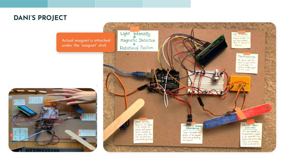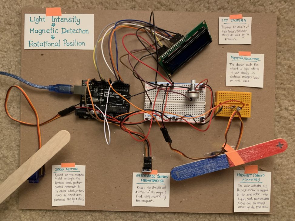

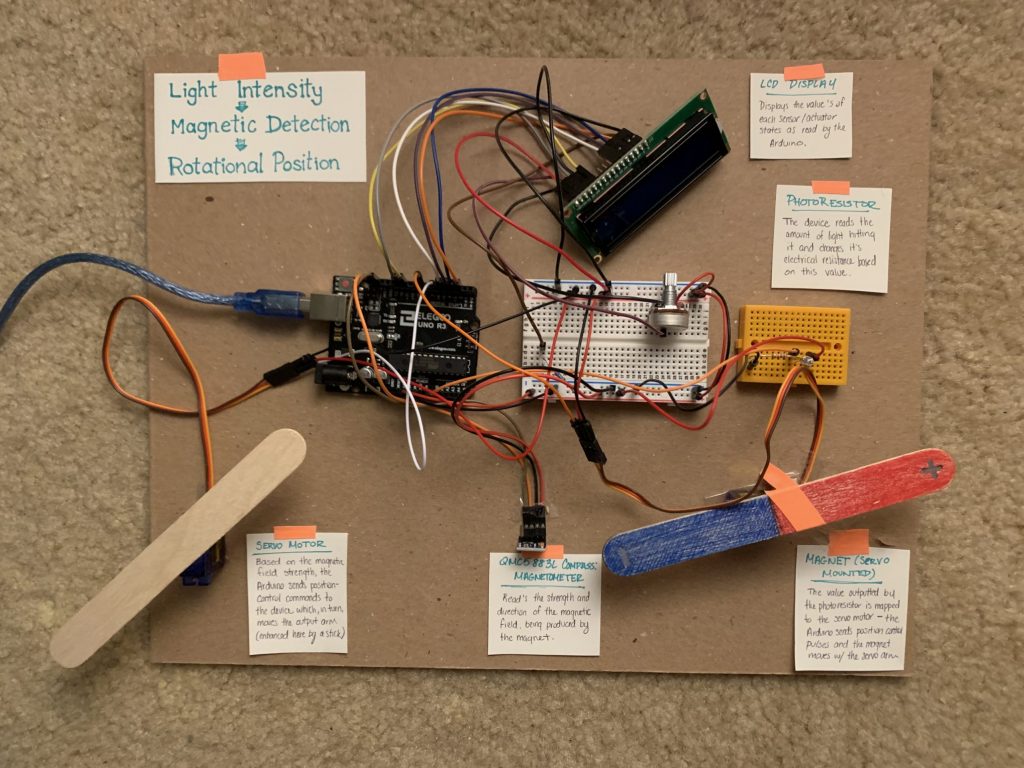
Dani’s final circuit with labels
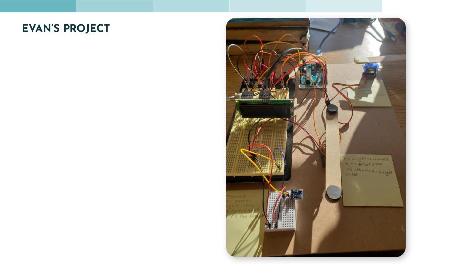
Evan’s Final Circuit
CIRCUIT OVERVIEW
For this Double Transducer project, we were given the initial input our circuit must read and the final output that it must produce as a result. We were left to decide on what the middle step would be. We explored a few different ideas at the start – perhaps color or sound could be an interesting middle step! However, after talking to Zach we quickly realized that these concepts involve a lot of complications as a middle step, leaving room for error and inconsistency when testing the circuit, so we moved away from those ideas fairly quickly. The final idea we landed upon was a fluctuating magnetic field!
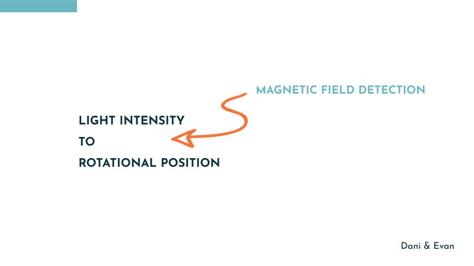
Initially, we wanted the magnetic field to fluctuate by creating an electromagnet and then controlling the amount of current going through it using the Arduino to change the power of the generated magnetic field. This ultimately didn’t work, most likely due to our wires lacking the resistance necessary to generate a powerful enough field, and so we pivoted and instead made the magnetic field force “fluctuate” by moving a magnet closer and further away from the magnetometer using a servo motor. The final input-output flow goes as such:
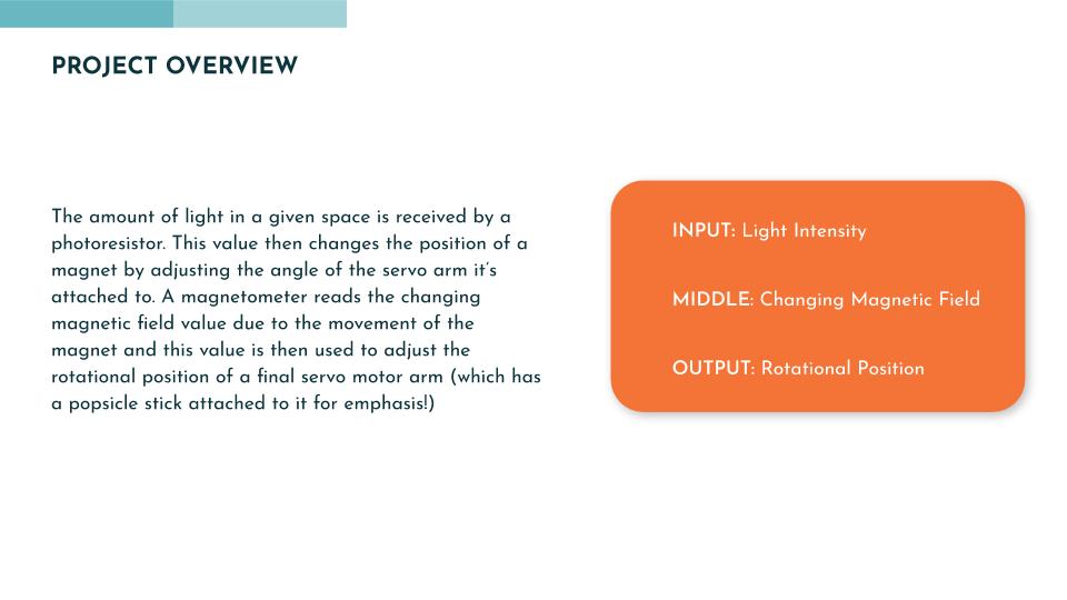
The amount of light in a given space is received by a photoresistor. This value then changes the position of a magnet by adjusting the angle of the servo arm it’s attached to. A magnetometer reads the changing magnetic field value due to the movement of the magnet and this value is then used to adjust the rotational position of a final servo motor arm (which has a popsicle stick attached to it for emphasis!)
STEPS TO COMPLETION
Once we decided on what we wanted our final input-output chain to be, it was time to begin the tough part of the project – actually getting it to work in the way that we wanted it to. We started with a few haphazard experiments that covered a broad range of design problems we wanted to tackle during our first, in-class, meetings but this strategy left me feeling a bit all over the place and ambivalent since we weren’t making notable progress. However, we soon switched our approach to be a more singular problem based and we got into a better progress groove. We started by tackling one of the two big unknowns: the magnetometer. Neither of us had used this sensor before and so we wanted to understand how it works (physically and code-wise) before tackling circuit components we were more familiar with.
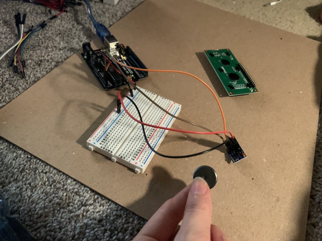
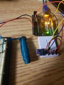
Testing the magnetometer and wiring
Then, we began to look at the other primary unknown and an area of uncertainty: namely the electromagnet component and the LCD screen. While Evan worked on the electromagnet and trying to resolve the wiring and code associated with that, Dani began to figure out the wiring and code for the LCD screen which was a bit different to years prior (since our LCD displays didn’t have the same “backpack” that was described in the course documentation).
Dani encountered some minor wiring errors and code errors (formatting wise) while trying to get the display to work. In the end, however, the biggest challenge about the display was the sheer amount of wires needed to hook it up leading to visual clutter and physical debugging issues. That and the fact that there was a while when Dani didn’t understand why she wasn’t getting a display with my code and wiring seemingly correct (it turned out to be a simple potentiometer contrast issue in the end).
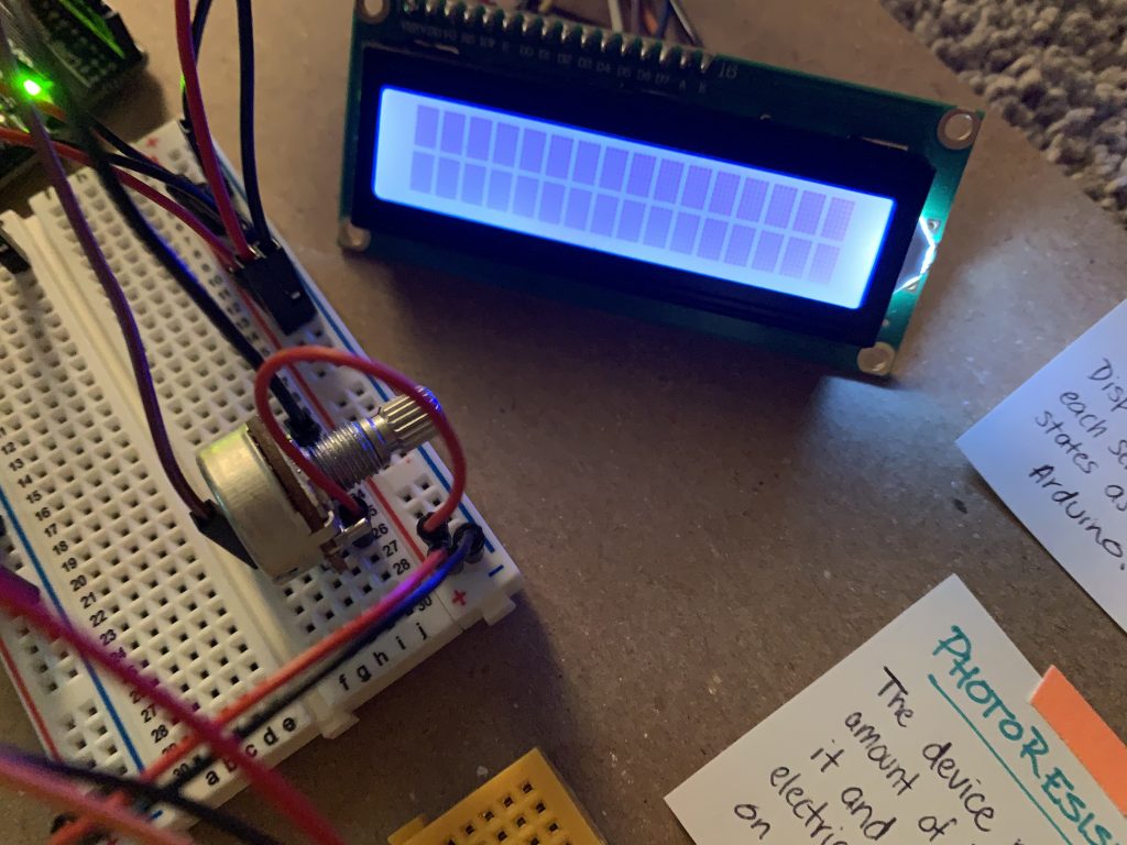
LCD not displaying information before a round of debugging
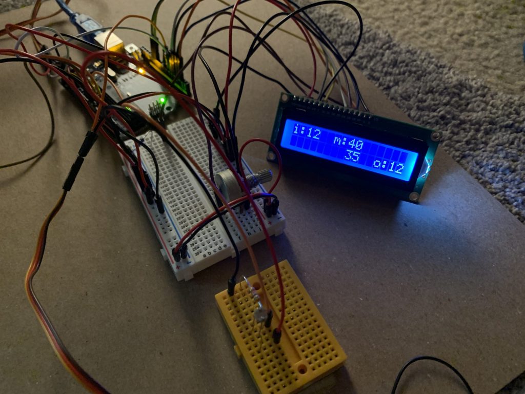
Final circuit closeup with functional LCD feedback
After wiring up the LCD screen and making sure the feedback was working properly (with pseudo-output numbers to start before we wired up the other sensors. Once the other sensors were wired and coded, their output values were placed into the LCD code’s variables), Dani began to construct the rest of the circuit. She started with the photoresistor wiring and then moved onto the servo motor while Evan worked on the coding elements.

Wired photoresistor on another breadboard for neatness
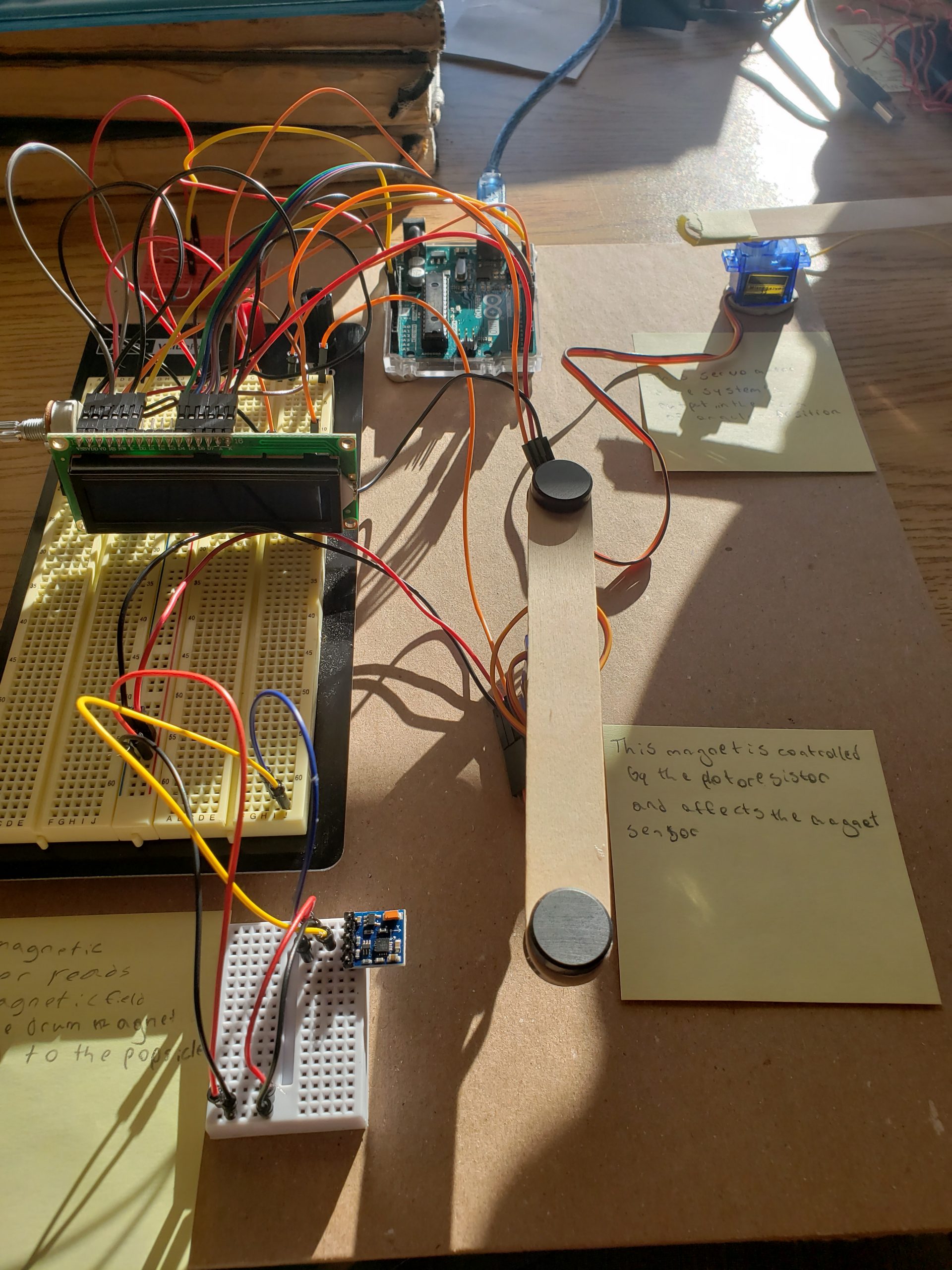
Circuit with the wired output servo moto, LCD screen, and magnetometer
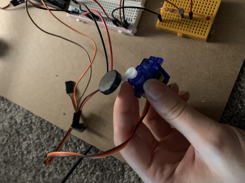
Magnet attached to a second servo motor for testing. This attachment was later removed en lieu of a popsicle stick that I painted like a magnet
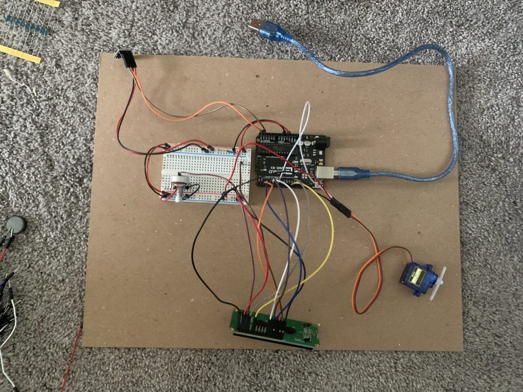
Final circuit construction
CHALLENGES AND DISCUSSION
- Wiring leading to visual clutter and debugging issues
- By wiring the LCD screen and magnetometer first, Dani cluttered up the breadboard from the get-go, thus making it harder to accurately place the servo motor and photoresistor pins. She added a second breadboard to the circuit to declutter the wires a bit more (along with adding a clearer sequential layout to the circuit by having the photoresistor as its own element). When it came to debugging the circuit, it took a while to trace the wires back to each pin they were connected to ensure that they were properly places and so, in the future, implementing a more strategic wiring method may prove to be useful.
- Scope issues for variable declaration
- When testing our code, we encountered several issues related to our variables – we had renamed some of them to provide better clarity as to what they do, but didn’t change all instances of that variable which lead to many snags along the way. While debugging these was fairly easy as we just had to scan the code to find the misnamed instances, ensuring to complete this full scan and check each time a variable is renamed would prevent some headaches.
- Changing ideas and rewriting code based on these changes
- This wasn’t a full challenge, but as our project developed and we pivoted from more complex ideas to ones that were more feasible within the time scope of our project, it was a bit tricky to correctly adjust only certain parts of the code. Knowing what code to write is once thing, but being thorough and ensuring that everything that needs to be adjusted has been changed and that there are no extraneous variables or residual code can be tricky.
- Electromagnet creation
- As mentioned in the above sections, we attempted to create an electromagnet that we could control the magnetic field instead of utilizing a normal bar magnet within our project. In the end, we had to shift to the bar magnet as we ran into too many issues with the electromagnet – we wish we could have tried some other wire coils to see if the different wire resistances made any difference for how the magnet functioned, but, the deciding factors of time and current access to resources left us to down-shift towards a standard magnetic interaction. Nevertheless, we still learned a lot about the use of a magnetometer and how to get different sensors to affect each other through this project and so we consider the learning outcomes to be a success no matter what.
-
The attempt at making an electromagnet.
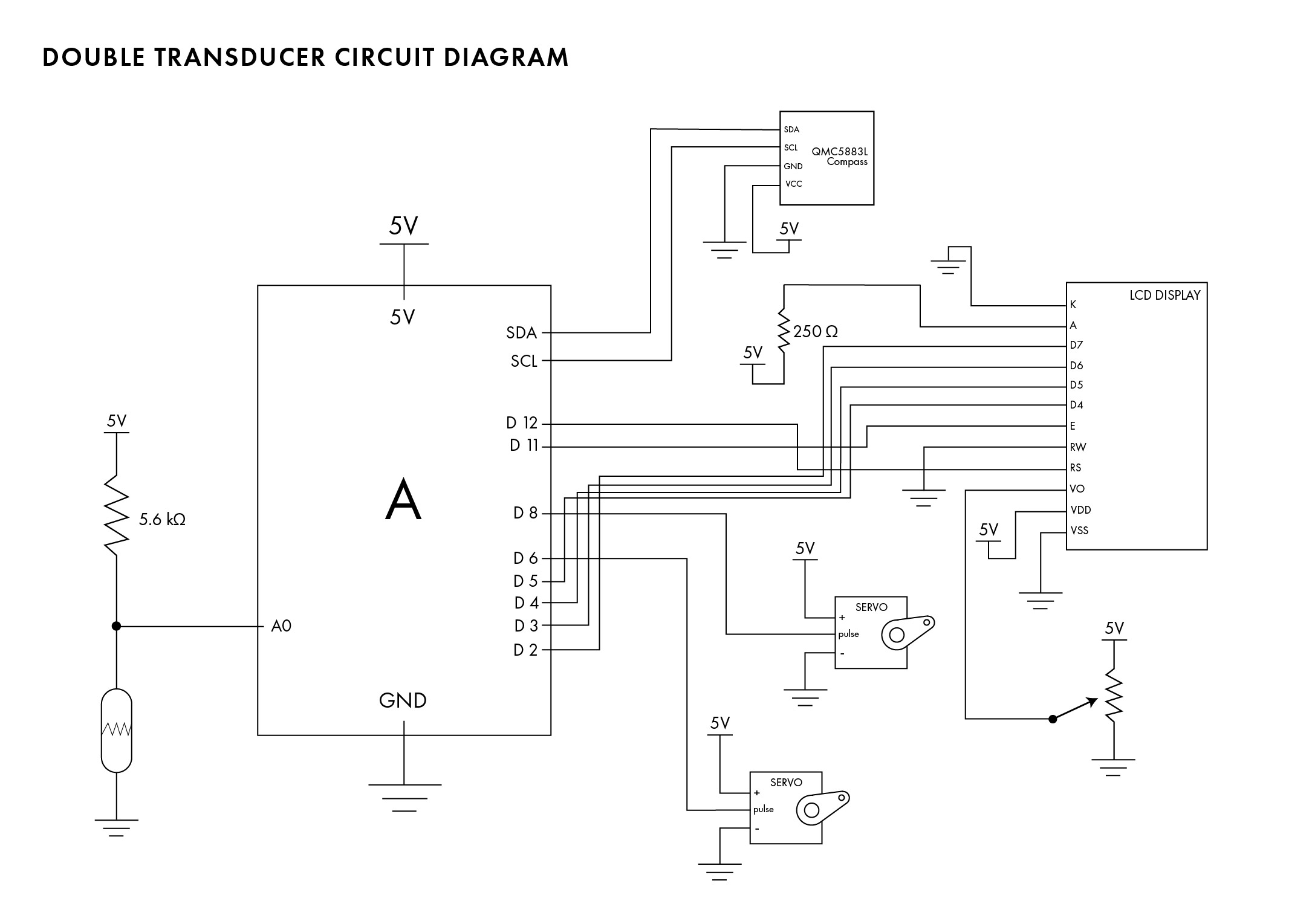
SCHEMATIC
CODE
/*
* Project 1
* Dani Delgado (ddelgad1) and Evan Tipping (eftippin)
*
* Collaboration: The basic collaboration for this project was with eachother and asking our professor, Robert  *Zacharias, questions
* relating to the sensors we were using and the Arduino code libraries that helped us to use them effectively.
* Beyond this, we used TinkerCAD's simulator to understand the proper LED wiring and basic sample code.
*
* Challenge: We tried to make an electromagnet to use for this project instead of moving a standard magnet with a motor, but in the end
* we couldn't make a magnet with a powerful enough current to be detected by the mangetometer due to the wires we were using (low resitance is suspected).
* We overcame the problems that arose as a group by playing to our strengths - I worked towards the wiring and visual completion of the circuits while
* Evan worked on debugging the code.
*
* Next time: Virtual collaboration can be a bit tricky (expecially when sharing our physical circuit components and trying to debug eachother's
* work) but now that I have some practice, I think that I can improve this work flow. Furthermore, next time I will learn from my wiring mistakes
* and code blunders from this project, and apply more stratigic techniques when it comes to order of what to do (i.e. wiring the more complec components last
* and debugging as I go rather than building it all and debugging it all at once).
*
* Description: The code below reads the intensity of incoming light using a photo resistor. This value then changes the position of a magnet by adjusting
* the angle of a servo motor. A magnetometer reads the changing magnetic field value due to the movement of the magnet and this value is then used to
* adjust the rotational position of a final servo motor arm.

* Pin mapping:
*
* pin   | mode   | description
* ------|--------|------------
* 8     | output | output for the servo motor affected by the brightness value of the photoresitor
* 6     | output | output for the servo motor affected by the magnetic field
* A0    | input  | photoresitor input
* 11    |        | RS pin on LCD
* 12    |        | E pin on LCD
* 5     |        | D4 pin on LCD
* 4     |        | D5 pin on LCD
* 3     |        | D6 pin on LCD
* 2     |        | D7 pin on LCD
*
*/

#include <Servo.h>
#include <LiquidCrystal.h>
#include <QMC5883LCompass.h>

// This turns out to be an angle controlling a lodestone's pos
const int PHO_MIN = 0;
const int PHO_MAX = 1023;
const int MAG_OUT_MIN = 75;
const int MAG_OUT_MAX = 105;
const int MAG_IN_MIN = 0;
const int MAG_IN_MAX = 4000;
const int SRV_MIN = 0;
const int SRV_MAX = 180;

// Pin assignment
const int EMGPIN = 8;
const int SRVPIN = 6;
const int PHOPIN = A0;

// initialize the library with the numbers of the interface pins
LiquidCrystal lcd(12, 11, 5, 4, 3, 2);

// Variables for the screen display
int disp_pho_input;
int disp_mag_output;
int disp_mag_input;
int disp_srv_output;

unsigned long timer = 0;
const unsigned long WAIT = 500;

// Init Servos
Servo output_motor;
Servo magnet_motor;

// Init compass
QMC5883LCompass compass;

void setup(void) {
  //for communication
  Serial.begin (115200);
  Serial.setTimeout(50);

  // Input 1
  pinMode(PHOPIN, INPUT);
  // Output 1
  magnet_motor.attach(EMGPIN);
  // Input 2
  compass.init();
  // Output 2
  output_motor.attach(SRVPIN);

  lcd.begin(16, 2);
}

int get_bright() {
  int bright_in = analogRead(PHOPIN);
  disp_pho_input = map(bright_in, 0, 1023, 0, 99);
  return bright_in;
}

int bright_to_mag_str(int bright_in) {
  // Takes brightness and converts it to magnetic field strength
  int strength_out = map(bright_in, PHO_MIN, PHO_MAX, MAG_OUT_MIN, MAG_OUT_MAX);
  disp_mag_output = map(strength_out, MAG_OUT_MIN, MAG_OUT_MAX , 0, 99);
  return strength_out;
}

int mag_str_to_angle(int strength_in) {
  int angle = map(strength_in, MAG_IN_MIN, MAG_IN_MAX, SRV_MIN, SRV_MAX);
  disp_srv_output = map(angle, SRV_MIN, SRV_MAX , 0, 99);
  return angle;
}

void write_strength(int strength_out) {
  magnet_motor.write(strength_out);
}

int read_strength(){
  compass.read();
  int y = compass.getY()/10;
  disp_mag_input = map(y, MAG_IN_MIN, MAG_IN_MAX , 0, 99);
  return abs(y);
}

void angle_to_output(int angle) {
  output_motor.write(angle);
}

void loop() {
  int bright_in = get_bright(); // Hiding the actual acquisition
  int strength_out = bright_to_mag_str(bright_in);
  write_strength(strength_out);

  // Separate by write + read to magnet

  int strength_in = read_strength();
  int angle = mag_str_to_angle(strength_in);
  angle_to_output(angle);

  //LCD screen feedback
  lcd.print((String)"i:" + disp_pho_input);

  lcd.setCursor(6, 0);
  lcd.print((String) "m:" + disp_mag_output);

  lcd.setCursor(8, 1);
  lcd.print(disp_mag_input);

  lcd.setCursor(12, 1);
  lcd.print((String) "o:" + disp_srv_output);

  delay(500);

  //communication loop
  if (millis() - timer > WAIT){
    int angle = mag_str_to_angle(strength_in);
    angle_to_output(angle);
       timer = millis();
       Serial.println(angle);
  }
}

void serialEvent(){
  /*  You do *not* need to call this function in your loop;
      it is a special function that will run whenever serial
      data flows into the Arduino. */

  /*  The function assumes your machine's input value
      is called "inVal" (change that variable name as needed) */

  // if there is incoming serial data, read it
  int bright_in = analogRead(PHOPIN);
  while (Serial.available() > 0){
    // interpret incoming digits as integer and save into inVal
    bright_in = Serial.parseInt();
  }
}
PRESENTATION SLIDES
The final section of this documentation is the presentation slides that were shared in class to overview our project’s capabilities and discuss the challenges we faced along the way. These slides can act as a TLDR for this documentation page, as they do not provide any additional in-depth information or personal thoughts about the project process.