In our double transducer project, we took a light as input, transduced it to to a motor which affected a read of tilt. The tilt was then transduced once more to the rotational speed of a stepper motor output.
TinkerCad Circuit
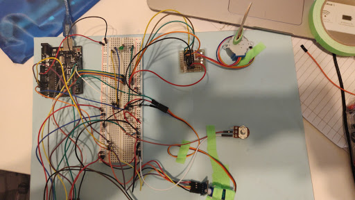
Physical Overview
overhead view of Connor’s circuit
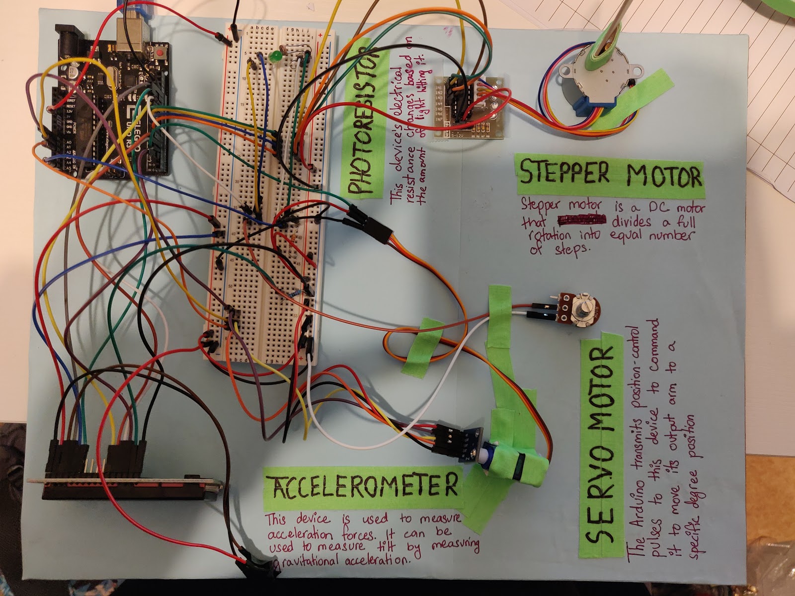
overhead view of Sruti’s circuit
Project Video
Notable Details
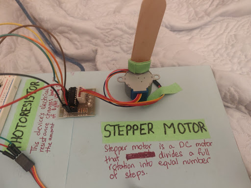
For the stepper motor, to make the rotational speed variations more obvious, we attached a popsicle stick to the rotating part of the motor.
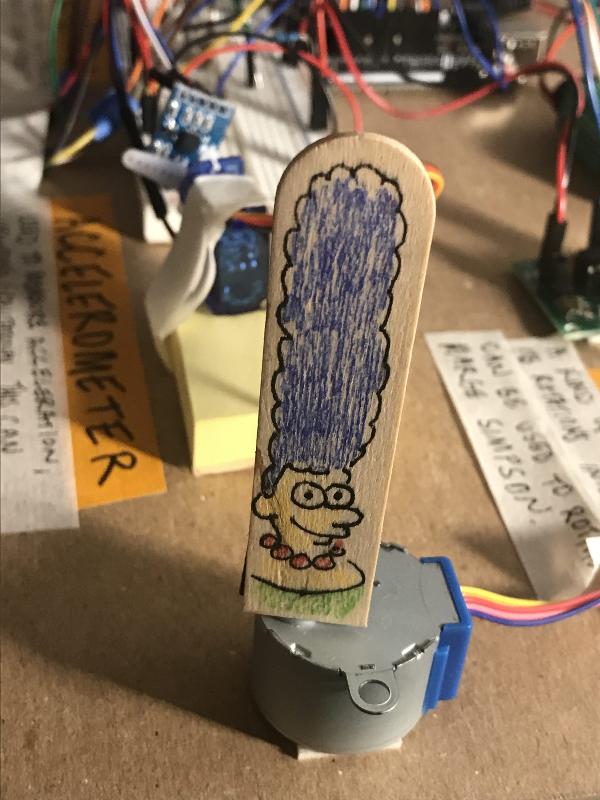
Drawing a Marge Simpson on one side of the popsicle stick helps make movement even more obvious. In this setup, the stick is mounted with a small strip of magnetic tape.
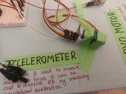
The accelerometer is screwed onto the servo motor so that it rotates as the servo motor changes its angle, tilting the accelerometer.
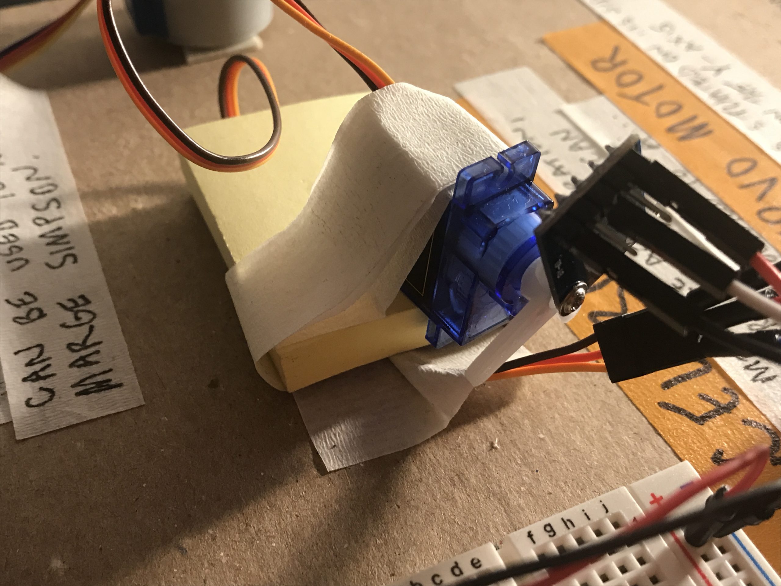
To maximize the range of motion, in this setup the servo is mounted on a small deck of post-it notes. This keeps the mounted accelerometer and its related wires from dragging.
Simple Narrative Description
This project is a double transducer that converts light intensity into tilt which is then translated into rotational intensity. We use an LED which is connected to a potentiometer to vary the brightness of the LED, which is then read by a photoresistor. The photoresistor reading is then sent to a servo motor, whose angle is adjusted based on the input it gets. The accelerometer is attached to the servo and hence it also rotates with the servo, providing different tilt readings. These readings are then mapped to a stepper motor, whose rotation speed varies based on its input.
Progress Images
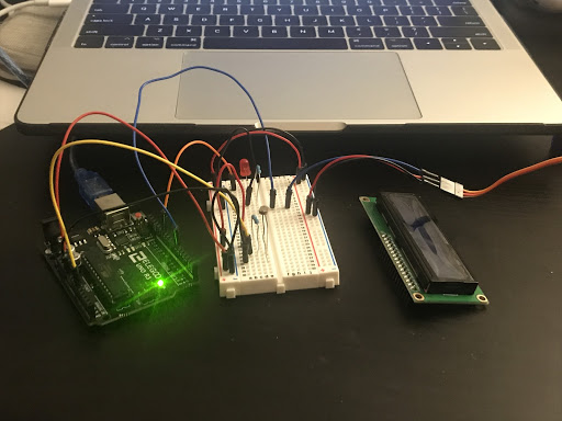
This image shows the first phase of our double transducer, the LED and a photoresistor which reads the light intensity.
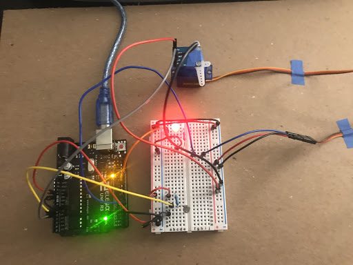
This image shows the light intensity step which is then connected to a servo motor which is connected to the tilt sensor.
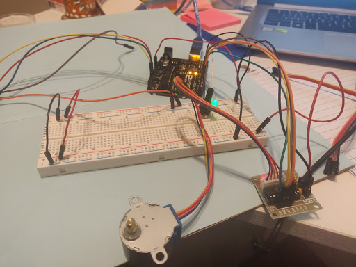
This shows the first and the last phases, light intensity and the stepper motor connected to the arduino.
This is an image that shows the entire circuit wired up, except for the LED screen.
Discussion
When we began working on this project, it sounded a lot more straightforward than it turned out to be. The light intensity step was quite easy and done very quickly. We did have a slight challenge with getting a large range of readings from the photoresistor, probably because the LED is not very bright and the background light contributes to a big part of the photoresistor’s reading. However, by adjusting the range of values from which the photoresistor readings are mapped to servo motor readings, we overcame the issue of very small angle change due to small change in photoresistor readings.
The second main issue we faced was that the Servo motor and the stepper motor both would not function at the same time, and if they did, they wouldn’t function smoothly or properly. We later, after help from the professor, realized that this was due to a large amount of power consumption by the stepper motor, which doesn’t allow the two of them to function well together. However, we were unable to fix that error as we diagnosed the problem during the project presentation. In order to slightly improve the functioning of the two motors, we used the same trick as we used for the photoresistor, we mapped a smaller range of tilt values to a much larger range of stepper motor rotation speeds so that small incremental changes would still look bigger.
Overall, there was a lot we learned through this project. One of the main things was that physical parts don’t always work like they are supposed to. We don’t get readings as clearly and easily as we get through a simulation. It also made us realize how much more time it takes to make it work. In general, we went from knowing how to build a very basic circuit to a decently complicated double transducer through this project.
Schematic
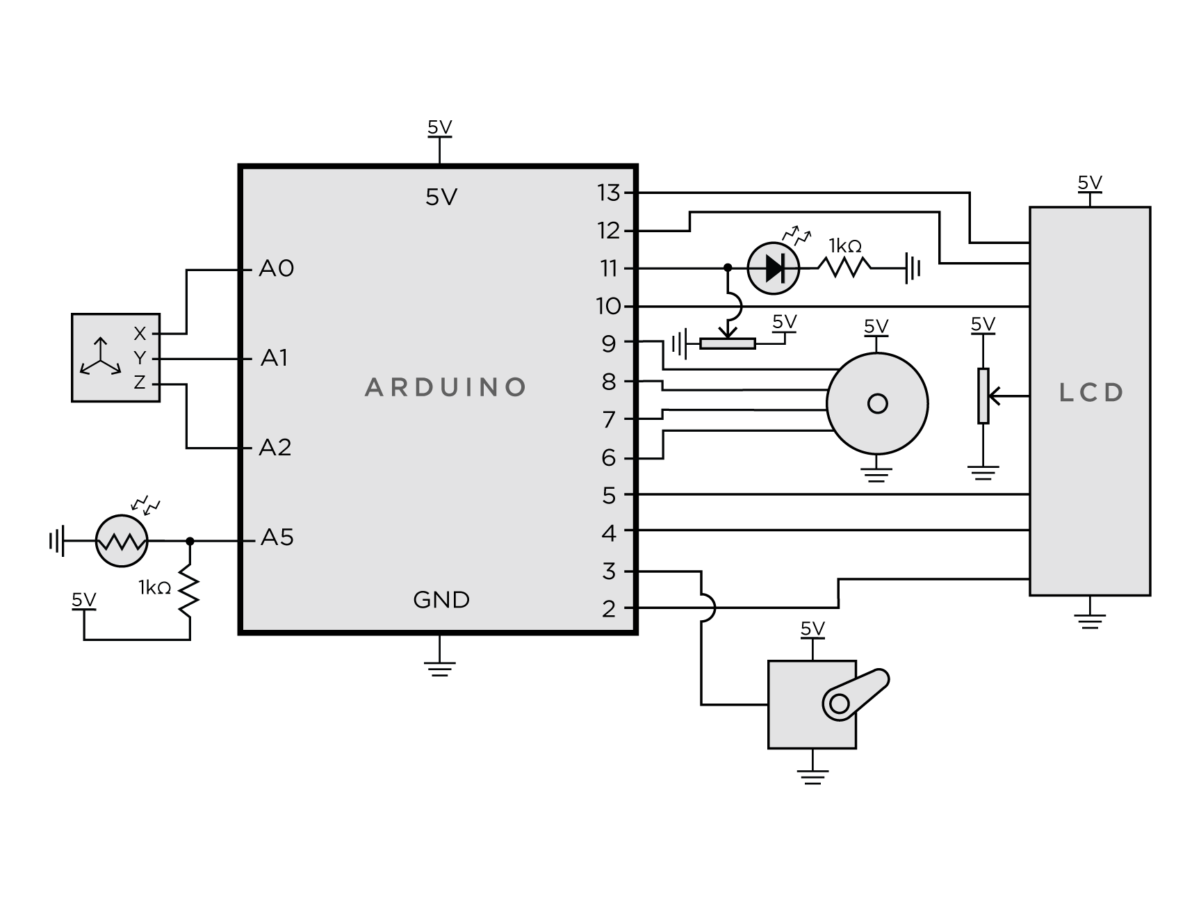
Our circuitry schematic, rendered in Adobe Illustrator after a CircuitLab crash
Code
- <span class="com">/*
- * Tilt Tranducer - Light -> Rotational Intensity
- *
- * Connor McGaffin (cmcgaffi) & Sruti Srinidhi (ssrinidh)
- *
- * Description: The code below takes the readings from a photoresistor and maps
- * it to an angle to which the servo motor rotates. As the servo motor rotates,
- * the accelerometer rotates as well and the code reads the accelerometer
- * readings and maps it to a rotational speed for the stepper motor, which
- * ultimately changes the rotational intensity.
- *
- * Pin mapping:
- *
- * pin | mode | description
- * ------|--------|------------
- * 2 input lcd
- * 3 output servo motor
- * 4 input lcd
- * 5 input lcd
- * 6 output stepper motor
- * 7 output stepper motor
- * 8 output stepper motor
- * 9 output stepper motor
- * 10 input lcd
- * 11 output LED output
- * 12 input lcd
- * 13 input lcd
- * A0 input Accelerometer x-axis value
- * A1 input Accelerometer y-axis value
- * A2 input Accelerometer z-axis value
- * A5 input Photoresistor value
- *
- */</span><span class="pln">
- </span><span class="com">#include</span><span class="pln"> </span><span class="str"><Stepper.h></span><span class="pln">
- </span><span class="com">#include</span><span class="pln"> </span><span class="str"><Servo.h></span><span class="pln">
- </span><span class="com">#include</span><span class="pln"> </span><span class="str"><LiquidCrystal.h></span><span class="pln">
- </span><span class="com">// Number of steps per revolution and step count for stepper motor</span><span class="pln">
- </span><span class="kwd">const</span><span class="pln"> </span><span class="kwd">int</span><span class="pln"> stepsPerRevolution </span><span class="pun">=</span><span class="pln"> </span><span class="lit">200</span><span class="pun">;</span><span class="pln">
- </span><span class="kwd">int</span><span class="pln"> stepCount </span><span class="pun">=</span><span class="pln"> </span><span class="lit">0</span><span class="pun">;</span><span class="pln">
- </span><span class="com">// initialize motors and LCD objects and their pins</span><span class="pln">
- </span><span class="typ">Stepper</span><span class="pln"> myStepper</span><span class="pun">(</span><span class="pln">stepsPerRevolution</span><span class="pun">,</span><span class="pln"> </span><span class="lit">6</span><span class="pun">,</span><span class="lit">7</span><span class="pun">,</span><span class="lit">8</span><span class="pun">,</span><span class="lit">9</span><span class="pun">);</span><span class="pln">
- </span><span class="typ">Servo</span><span class="pln"> tiltMotor</span><span class="pun">;</span><span class="pln">
- </span><span class="typ">LiquidCrystal</span><span class="pln"> lcd</span><span class="pun">(</span><span class="lit">13</span><span class="pun">,</span><span class="pln"> </span><span class="lit">12</span><span class="pun">,</span><span class="pln"> </span><span class="lit">10</span><span class="pun">,</span><span class="pln"> </span><span class="lit">5</span><span class="pun">,</span><span class="pln"> </span><span class="lit">4</span><span class="pun">,</span><span class="pln"> </span><span class="lit">2</span><span class="pun">);</span><span class="pln">
- </span><span class="com">//Initialize pin constants</span><span class="pln">
- </span><span class="kwd">const</span><span class="pln"> </span><span class="kwd">int</span><span class="pln"> xPin </span><span class="pun">=</span><span class="pln"> A0</span><span class="pun">;</span><span class="pln">
- </span><span class="kwd">const</span><span class="pln"> </span><span class="kwd">int</span><span class="pln"> yPin </span><span class="pun">=</span><span class="pln"> A1</span><span class="pun">;</span><span class="pln">
- </span><span class="kwd">const</span><span class="pln"> </span><span class="kwd">int</span><span class="pln"> zPin </span><span class="pun">=</span><span class="pln"> A2</span><span class="pun">;</span><span class="pln">
- </span><span class="kwd">const</span><span class="pln"> </span><span class="kwd">int</span><span class="pln"> LEDPIN </span><span class="pun">=</span><span class="pln"> </span><span class="lit">11</span><span class="pun">;</span><span class="pln">
- </span><span class="kwd">const</span><span class="pln"> </span><span class="kwd">int</span><span class="pln"> PHOTOPIN </span><span class="pun">=</span><span class="pln"> A5</span><span class="pun">;</span><span class="pln">
- </span><span class="kwd">const</span><span class="pln"> </span><span class="kwd">int</span><span class="pln"> SERVOTILTPIN </span><span class="pun">=</span><span class="pln"> </span><span class="lit">3</span><span class="pun">;</span><span class="pln">
- </span><span class="kwd">unsigned</span><span class="pln"> </span><span class="kwd">long</span><span class="pln"> timer </span><span class="pun">=</span><span class="pln"> </span><span class="lit">0</span><span class="pun">;</span><span class="pln">
- </span><span class="kwd">int</span><span class="pln"> photoVal</span><span class="pun">;</span><span class="pln">
- </span><span class="kwd">void</span><span class="pln"> setup</span><span class="pun">()</span><span class="pln"> </span><span class="pun">{</span><span class="pln">
- pinMode</span><span class="pun">(</span><span class="pln">LEDPIN</span><span class="pun">,</span><span class="pln"> OUTPUT</span><span class="pun">);</span><span class="pln">
- pinMode</span><span class="pun">(</span><span class="pln">yPin</span><span class="pun">,</span><span class="pln"> INPUT</span><span class="pun">);</span><span class="pln">
- pinMode</span><span class="pun">(</span><span class="pln">PHOTOPIN</span><span class="pun">,</span><span class="pln"> INPUT</span><span class="pun">);</span><span class="pln">
- tiltMotor</span><span class="pun">.</span><span class="pln">attach</span><span class="pun">(</span><span class="pln">SERVOTILTPIN</span><span class="pun">);</span><span class="pln">
- lcd</span><span class="pun">.</span><span class="kwd">begin</span><span class="pun">(</span><span class="lit">16</span><span class="pun">,</span><span class="pln"> </span><span class="lit">2</span><span class="pun">);</span><span class="pln">
- </span><span class="typ">Serial</span><span class="pun">.</span><span class="kwd">begin</span><span class="pun">(</span><span class="lit">115200</span><span class="pun">);</span><span class="pln">
- </span><span class="typ">Serial</span><span class="pun">.</span><span class="pln">setTimeout</span><span class="pun">(</span><span class="lit">50</span><span class="pun">);</span><span class="pln">
- </span><span class="pun">}</span><span class="pln">
- </span><span class="kwd">void</span><span class="pln"> loop</span><span class="pun">()</span><span class="pln"> </span><span class="pun">{</span><span class="pln">
- </span><span class="kwd">int</span><span class="pln"> tiltAngle</span><span class="pun">;</span><span class="pln">
- </span><span class="kwd">int</span><span class="pln"> yPinVal</span><span class="pun">;</span><span class="pln">
- </span><span class="com">// Light write and read</span><span class="pln">
- digitalWrite</span><span class="pun">(</span><span class="pln">LEDPIN</span><span class="pun">,</span><span class="pln">HIGH</span><span class="pun">);</span><span class="pln">
- photoVal </span><span class="pun">=</span><span class="pln"> analogRead</span><span class="pun">(</span><span class="pln">PHOTOPIN</span><span class="pun">);</span><span class="pln">
- </span><span class="com">//Convert to angle of servo motor</span><span class="pln">
- tiltAngle </span><span class="pun">=</span><span class="pln"> map</span><span class="pun">(</span><span class="pln">photoVal</span><span class="pun">,</span><span class="pln"> </span><span class="lit">500</span><span class="pun">,</span><span class="pln"> </span><span class="lit">1000</span><span class="pun">,</span><span class="pln"> </span><span class="lit">0</span><span class="pun">,</span><span class="pln"> </span><span class="lit">180</span><span class="pun">);</span><span class="pln">
- tiltMotor</span><span class="pun">.</span><span class="pln">write</span><span class="pun">(</span><span class="pln">tiltAngle</span><span class="pun">);</span><span class="pln">
- </span><span class="com">//Read accelerometer</span><span class="pln">
- yPinVal </span><span class="pun">=</span><span class="pln"> analogRead</span><span class="pun">(</span><span class="pln">yPin</span><span class="pun">);</span><span class="pln">
- </span><span class="com">//Change rotational intensity of stepper motor</span><span class="pln">
- </span><span class="kwd">int</span><span class="pln"> motorSpeed </span><span class="pun">=</span><span class="pln"> map</span><span class="pun">(</span><span class="pln">yPinVal</span><span class="pun">,</span><span class="pln"> </span><span class="lit">200</span><span class="pun">,</span><span class="pln"> </span><span class="lit">1023</span><span class="pun">,</span><span class="pln"> </span><span class="lit">0</span><span class="pun">,</span><span class="pln"> </span><span class="lit">100</span><span class="pun">);</span><span class="pln">
- </span><span class="kwd">if</span><span class="pln"> </span><span class="pun">(</span><span class="pln">motorSpeed </span><span class="pun">></span><span class="pln"> </span><span class="lit">0</span><span class="pun">)</span><span class="pln"> </span><span class="pun">{</span><span class="pln">
- myStepper</span><span class="pun">.</span><span class="pln">setSpeed</span><span class="pun">(</span><span class="pln">motorSpeed</span><span class="pun">);</span><span class="pln">
- myStepper</span><span class="pun">.</span><span class="pln">step</span><span class="pun">(</span><span class="pln">stepsPerRevolution </span><span class="pun">/</span><span class="pln"> </span><span class="lit">100</span><span class="pun">);</span><span class="pln">
- </span><span class="pun">}</span><span class="pln">
- </span><span class="com">//Output details on LCD</span><span class="pln">
- lcd</span><span class="pun">.</span><span class="pln">setCursor</span><span class="pun">(</span><span class="lit">0</span><span class="pun">,</span><span class="pln"> </span><span class="lit">0</span><span class="pun">);</span><span class="pln">
- lcd</span><span class="pun">.</span><span class="kwd">print</span><span class="pun">(</span><span class="str">"i:"</span><span class="pun">);</span><span class="pln">
- lcd</span><span class="pun">.</span><span class="pln">setCursor</span><span class="pun">(</span><span class="lit">2</span><span class="pun">,</span><span class="lit">0</span><span class="pun">);</span><span class="pln">
- lcd</span><span class="pun">.</span><span class="kwd">print</span><span class="pun">(</span><span class="pln">map</span><span class="pun">(</span><span class="pln">photoVal</span><span class="pun">,</span><span class="lit">0</span><span class="pun">,</span><span class="lit">1023</span><span class="pun">,</span><span class="lit">100</span><span class="pun">,</span><span class="lit">0</span><span class="pun">));</span><span class="pln">
- lcd</span><span class="pun">.</span><span class="pln">setCursor</span><span class="pun">(</span><span class="lit">5</span><span class="pun">,</span><span class="lit">0</span><span class="pun">);</span><span class="pln">
- lcd</span><span class="pun">.</span><span class="kwd">print</span><span class="pun">(</span><span class="str">"m:"</span><span class="pun">);</span><span class="pln">
- lcd</span><span class="pun">.</span><span class="pln">setCursor</span><span class="pun">(</span><span class="lit">7</span><span class="pun">,</span><span class="lit">0</span><span class="pun">);</span><span class="pln">
- lcd</span><span class="pun">.</span><span class="kwd">print</span><span class="pun">(</span><span class="pln">map</span><span class="pun">(</span><span class="pln">tiltAngle</span><span class="pun">,</span><span class="pln"> </span><span class="lit">0</span><span class="pun">,</span><span class="pln"> </span><span class="lit">180</span><span class="pun">,</span><span class="pln"> </span><span class="lit">0</span><span class="pln"> </span><span class="pun">,</span><span class="lit">100</span><span class="pun">));</span><span class="pln">
- lcd</span><span class="pun">.</span><span class="pln">setCursor</span><span class="pun">(</span><span class="lit">7</span><span class="pun">,</span><span class="lit">1</span><span class="pun">);</span><span class="pln">
- lcd</span><span class="pun">.</span><span class="kwd">print</span><span class="pun">(</span><span class="pln">map</span><span class="pun">(</span><span class="pln">yPinVal</span><span class="pun">,</span><span class="pln"> </span><span class="lit">300</span><span class="pun">,</span><span class="pln"> </span><span class="lit">600</span><span class="pun">,</span><span class="pln"> </span><span class="lit">0</span><span class="pln"> </span><span class="pun">,</span><span class="lit">100</span><span class="pun">));</span><span class="pln">
- lcd</span><span class="pun">.</span><span class="pln">setCursor</span><span class="pun">(</span><span class="lit">10</span><span class="pun">,</span><span class="lit">1</span><span class="pun">);</span><span class="pln">
- lcd</span><span class="pun">.</span><span class="kwd">print</span><span class="pun">(</span><span class="str">"o:"</span><span class="pun">);</span><span class="pln">
- lcd</span><span class="pun">.</span><span class="pln">setCursor</span><span class="pun">(</span><span class="lit">12</span><span class="pun">,</span><span class="lit">1</span><span class="pun">);</span><span class="pln">
- lcd</span><span class="pun">.</span><span class="kwd">print</span><span class="pun">(</span><span class="pln">motorSpeed</span><span class="pun">);</span><span class="pln">
- delay</span><span class="pun">(</span><span class="lit">15</span><span class="pun">);</span><span class="pln">
- </span><span class="pun">}</span>