by Arleen Liu and Jina Lee
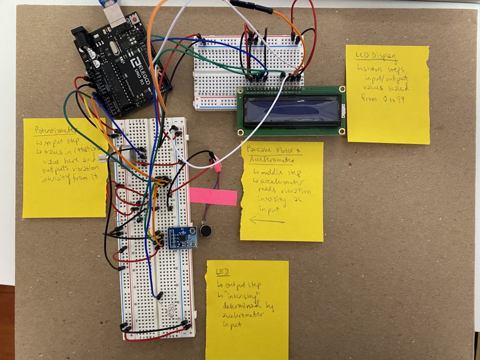
An input taken from the rotational position of the potentiometer will determine the speed of a connected pancake vibration motor accordingly, whose vibration intensity will be read by a nearby accelerometer, which, in turn, takes those vibration readings and outputs an appropriate intensity for the output LED.
Screengrab of TinkerCAD:
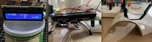
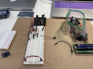
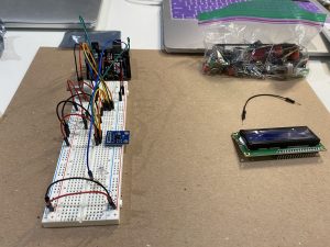
Overall photo for proportion and scale:

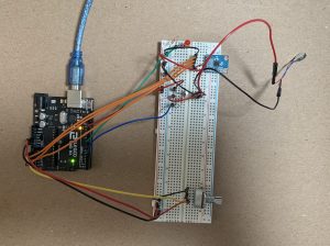
An overall view of Arleen’s final physical circuit layout.
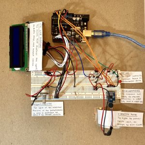
An overall view of Jina’s final physical circuit layout.
Detail photos of highlighted circuit aspects:
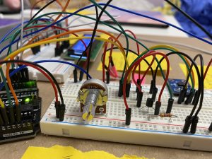
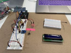
Our circuit input – a potentiometer for rotational position
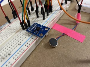
A closer shot of the middle step in our circuit featuring the pancake motor and accelerometer
In order to keep the wires organized, used Pringles to cut in half to use as a holder. There is metal in the inside of the can, so had to layer paper between so there weren’t any random circulations of energy.
Videos of working circuits:
Due to not having a tripod, it was difficult to film without shaking.
Progress images:
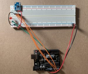
The beginning stages of Arleen’s circuit – only the basic parts are wired up
Arleen’s circuit some more progress in the wiring featuring the addition of an accelerometer
Arleen’s circuit in it’s final stages of completion with only the LCD display left to wire up
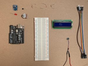
In order to start, Jina found all the pieces so that there would not be any confusion later on.
Here is Jina’s progress as she starts to add more of the components onto the board.
At this time, the LED, accelerometer, pancake vibration motor, and potentiometer were connected. Jina now just has to add the LCD board!
Discussion:
Since this was the biggest and most complicated circuit we had built yet, the overall process, from ideation to building the simulation to actually wiring the circuit all presented novel obstacles for us to learn and grow from that will prepare us for future bigger projects.
During the ideation phase, we already encountered the struggle of being creative given the limited parts we were provided in the kit, and some of our ideas themselves were not viable or had errors in misunderstanding parts. For example, we had an idea to use the rotary encoder to somehow send electrical pulses and read it by a transistor as our circuit’s middle step, but upon receiving clarification for the actual functionality of a rotary encoder, we had to scrap that idea. In addition, going through the ideation process really opened our eyes to the vast array of input and output forms out in the world, something we would not have given thought before. In the end, we were able to implement an idea that exuded creativity, using vibration, while also having an element of simplicity to it that made it possible for us to build as beginners to electronics.
After settling on an idea for our circuit came a step that we were more familiar with: building the circuit in TinkerCAD. This step was definitely the most comfortable one for us, having built a few TinkerCAD circuits in class already for homework assignments. Most of this was a smooth process, especially the setup, but we did run into a few minor difficulties in dealing with the complexity of the wiring, especially for the LCD display, and researching how exactly the components were supposed to be wired up through other example TinkerCAD circuits. Coding the circuit was much of the same process as wiring – researching how to interact with the new components in code and encountering a few bugs from the complexity of the code relative to previous homework assignments.
For the physical building aspect, this step introduced an overall understanding of both the wiring and code. Before we physically started, there was some confusion about missing the pancake vibration motor due to its small size and placement in the kit. We had to briefly re-evaluate and figure out another option by using the stepper motor and offset magnets. Fortunately, we were able to find the pancake vibration motor which was hidden in a bag full of other small components. Once we were able to get all the parts, we started to configure the whole circuit. In order to connect the pancake vibration motor, we had to solder or tape them together which we choose later. Due to the inexperience of stripping wires, the pancake vibration motor ground was cut accidentally much shorter than the 5v wire. In the end, we were both able to successfully connect all of our components to the Arduino. Overall, it was crucial for us to organize the wires so that it would not get confusing and cause problems later on.
Schematic Diagram:
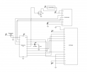
This is our schematic diagramming through CircuitLab.
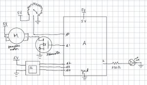
Here is the original schematic drawing of our project.
Our code:
- <span class="com">/*
- * Project 1: Double Transducer
- * Arleen Liu and Jina Lee
- *
- * Collaboration: RaspberryUser, a tinkerCAD designer, who helped
- * us get a better understanding of how to connect the LCD display
- * with a circuit.
- *
- * emumcu, a tinkerCAD designer, who helped us understand how to
- * connect LCD display with a potentiometer. This was helpful for us
- * to see other ways to put connect the wirings together.
- *
- * Challenge: Figuring out how to wire all the components
- * properly and configuring code to translate inputs to
- * outputs respectively.
- *
- * Next Time: Look at more example Tinkercad circuits with parts
- * to learn how to work with them properly. Carefully and closely
- * look at our ciruits when error arises to fix.
- *
- * Description: An input is taken from the rotational potistion
- * of the potentiometer will determine the speed of a connected
- * pancake vibration motor accordingly, whose vibration
- * inteniy will be read by an accelerometer, which takes the
- * vibation data and ouputs and intensity for the output LED.
- *
- * Pin mapping:
- *
- * pin | mode | description
- * ----|------|------------
- * A0 INPUT potentiometer
- * 9 OUTPUT red LED
- * A1 INPUT accelerometer
- * A2 INPUT accelerometer
- * A3 INPUT accelerometer
- * 6 OUTPUT pancake vibration motor
- * 5 OUTPUT DB4 LCD
- * 4 OUTPUT DB5 LCD
- * 3 OUTPUT DB6 LCD
- * 2 OUTPUT DB7 LCD
- * 12 OUTPUT RS LCD
- * 11 OUTPUT # LCD
- */</span><span class="pln">
- </span><span class="com">#include</span><span class="str"><LiquidCrystal.h></span><span class="pln">
- </span><span class="kwd">const</span><span class="pln"> </span><span class="kwd">int</span><span class="pln"> POT_PIN </span><span class="pun">=</span><span class="pln"> A0</span><span class="pun">;</span><span class="pln">
- </span><span class="kwd">const</span><span class="pln"> </span><span class="kwd">int</span><span class="pln"> X_PIN </span><span class="pun">=</span><span class="pln"> A3</span><span class="pun">;</span><span class="pln">
- </span><span class="kwd">const</span><span class="pln"> </span><span class="kwd">int</span><span class="pln"> Y_PIN </span><span class="pun">=</span><span class="pln"> A2</span><span class="pun">;</span><span class="pln">
- </span><span class="kwd">const</span><span class="pln"> </span><span class="kwd">int</span><span class="pln"> Z_PIN </span><span class="pun">=</span><span class="pln"> A1</span><span class="pun">;</span><span class="pln">
- </span><span class="kwd">const</span><span class="pln"> </span><span class="kwd">int</span><span class="pln"> MOTOR_PIN </span><span class="pun">=</span><span class="pln"> </span><span class="lit">6</span><span class="pun">;</span><span class="pln">
- </span><span class="kwd">const</span><span class="pln"> </span><span class="kwd">int</span><span class="pln"> DB4 </span><span class="pun">=</span><span class="pln"> </span><span class="lit">5</span><span class="pun">;</span><span class="pln">
- </span><span class="kwd">const</span><span class="pln"> </span><span class="kwd">int</span><span class="pln"> DB5 </span><span class="pun">=</span><span class="pln"> </span><span class="lit">4</span><span class="pun">;</span><span class="pln">
- </span><span class="kwd">const</span><span class="pln"> </span><span class="kwd">int</span><span class="pln"> DB6 </span><span class="pun">=</span><span class="pln"> </span><span class="lit">3</span><span class="pun">;</span><span class="pln">
- </span><span class="kwd">const</span><span class="pln"> </span><span class="kwd">int</span><span class="pln"> DB7 </span><span class="pun">=</span><span class="pln"> </span><span class="lit">2</span><span class="pun">;</span><span class="pln">
- </span><span class="kwd">const</span><span class="pln"> </span><span class="kwd">int</span><span class="pln"> E </span><span class="pun">=</span><span class="pln"> </span><span class="lit">11</span><span class="pun">;</span><span class="pln">
- </span><span class="kwd">const</span><span class="pln"> </span><span class="kwd">int</span><span class="pln"> RS </span><span class="pun">=</span><span class="pln"> </span><span class="lit">12</span><span class="pun">;</span><span class="pln">
- </span><span class="kwd">const</span><span class="pln"> </span><span class="kwd">int</span><span class="pln"> LED_PIN </span><span class="pun">=</span><span class="pln"> </span><span class="lit">9</span><span class="pun">;</span><span class="pln">
- </span><span class="kwd">const</span><span class="pln"> </span><span class="kwd">int</span><span class="pln"> TIME_SCALE </span><span class="pun">=</span><span class="pln"> </span><span class="lit">50</span><span class="pun">;</span><span class="pln">
- </span><span class="kwd">const</span><span class="pln"> </span><span class="kwd">int</span><span class="pln"> a_max </span><span class="pun">=</span><span class="pln"> </span><span class="lit">400</span><span class="pun">;</span><span class="pln">
- </span><span class="com">// Volts per G-Force</span><span class="pln">
- </span><span class="kwd">const</span><span class="pln"> </span><span class="kwd">float</span><span class="pln"> sensitivity </span><span class="pun">=</span><span class="pln"> </span><span class="lit">0.206</span><span class="pun">;</span><span class="pln">
- </span><span class="kwd">long</span><span class="pln"> timer1 </span><span class="pun">=</span><span class="pln"> </span><span class="lit">0</span><span class="pun">,</span><span class="pln"> timer2 </span><span class="pun">=</span><span class="pln"> </span><span class="lit">0</span><span class="pun">;</span><span class="pln">
- </span><span class="typ">LiquidCrystal</span><span class="pln"> lcd</span><span class="pun">(</span><span class="pln">RS</span><span class="pun">,</span><span class="pln"> E</span><span class="pun">,</span><span class="pln"> DB4</span><span class="pun">,</span><span class="pln"> DB5</span><span class="pun">,</span><span class="pln"> DB6</span><span class="pun">,</span><span class="pln"> DB7</span><span class="pun">);</span><span class="pln">
- </span><span class="kwd">void</span><span class="pln"> setup</span><span class="pun">()</span><span class="pln"> </span><span class="pun">{</span><span class="pln">
- </span><span class="com">//Initializing pins</span><span class="pln">
- pinMode</span><span class="pun">(</span><span class="pln">LED_PIN</span><span class="pun">,</span><span class="pln"> OUTPUT</span><span class="pun">);</span><span class="pln">
- pinMode</span><span class="pun">(</span><span class="pln">POT_PIN</span><span class="pun">,</span><span class="pln"> INPUT</span><span class="pun">);</span><span class="pln">
- pinMode</span><span class="pun">(</span><span class="pln">MOTOR_PIN</span><span class="pun">,</span><span class="pln"> OUTPUT</span><span class="pun">);</span><span class="pln">
- analogReference</span><span class="pun">(</span><span class="pln">EXTERNAL</span><span class="pun">);</span><span class="pln">
- </span><span class="com">//Initializing other elements</span><span class="pln">
- lcd</span><span class="pun">.</span><span class="kwd">begin</span><span class="pun">(</span><span class="lit">16</span><span class="pun">,</span><span class="pln"> </span><span class="lit">2</span><span class="pun">);</span><span class="pln">
- </span><span class="typ">Serial</span><span class="pun">.</span><span class="kwd">begin</span><span class="pun">(</span><span class="lit">9600</span><span class="pun">);</span><span class="pln">
- </span><span class="pun">}</span><span class="pln">
- </span><span class="kwd">void</span><span class="pln"> loop</span><span class="pun">()</span><span class="pln"> </span><span class="pun">{</span><span class="pln">
- </span><span class="com">//Reading input position value</span><span class="pln">
- </span><span class="kwd">int</span><span class="pln"> potVal </span><span class="pun">=</span><span class="pln"> analogRead</span><span class="pun">(</span><span class="pln">POT_PIN</span><span class="pun">);</span><span class="pln">
- </span><span class="com">//Converting to vibration</span><span class="pln">
- </span><span class="kwd">int</span><span class="pln"> vTime </span><span class="pun">=</span><span class="pln"> map</span><span class="pun">(</span><span class="pln">potVal</span><span class="pun">,</span><span class="pln"> </span><span class="lit">0</span><span class="pun">,</span><span class="pln"> </span><span class="lit">1023</span><span class="pun">,</span><span class="pln"> </span><span class="lit">0</span><span class="pun">,</span><span class="pln"> TIME_SCALE</span><span class="pun">);</span><span class="pln">
- </span><span class="com">//Controlling vibration intensity with potentiometer input</span><span class="pln">
- </span><span class="kwd">if</span><span class="pln"> </span><span class="pun">(</span><span class="pln">millis</span><span class="pun">()</span><span class="pln"> </span><span class="pun">-</span><span class="pln"> timer1 </span><span class="pun">>=</span><span class="pln"> </span><span class="pun">(</span><span class="pln">TIME_SCALE </span><span class="pun">-</span><span class="pln"> vTime</span><span class="pun">)</span><span class="pln">
- </span><span class="pun">&&</span><span class="pln"> millis</span><span class="pun">()</span><span class="pln"> </span><span class="pun">-</span><span class="pln"> timer1 </span><span class="pun"><=</span><span class="pln"> TIME_SCALE</span><span class="pun">)</span><span class="pln"> </span><span class="pun">{</span><span class="pln">
- digitalWrite</span><span class="pun">(</span><span class="pln">MOTOR_PIN</span><span class="pun">,</span><span class="pln"> HIGH</span><span class="pun">);</span><span class="pln">
- </span><span class="typ">Serial</span><span class="pun">.</span><span class="pln">println</span><span class="pun">(</span><span class="str">"registering"</span><span class="pun">);</span><span class="pln">
- </span><span class="pun">}</span><span class="pln"> </span><span class="kwd">else</span><span class="pln"> </span><span class="kwd">if</span><span class="pln"> </span><span class="pun">(</span><span class="pln">millis</span><span class="pun">()</span><span class="pln"> </span><span class="pun">-</span><span class="pln"> timer1 </span><span class="pun">>=</span><span class="pln"> TIME_SCALE</span><span class="pun">)</span><span class="pln"> </span><span class="pun">{</span><span class="pln">
- digitalWrite</span><span class="pun">(</span><span class="pln">MOTOR_PIN</span><span class="pun">,</span><span class="pln"> LOW</span><span class="pun">);</span><span class="pln">
- timer1 </span><span class="pun">=</span><span class="pln"> millis</span><span class="pun">();</span><span class="pln">
- </span><span class="pun">}</span><span class="pln">
- </span><span class="kwd">float</span><span class="pln"> x</span><span class="pun">;</span><span class="pln">
- </span><span class="kwd">float</span><span class="pln"> y</span><span class="pun">;</span><span class="pln">
- </span><span class="kwd">float</span><span class="pln"> z</span><span class="pun">;</span><span class="pln">
- </span><span class="com">// Read acceleration pins and handle sensitivity</span><span class="pln">
- x </span><span class="pun">=</span><span class="pln"> </span><span class="pun">(</span><span class="pln">analogRead</span><span class="pun">(</span><span class="pln">X_PIN</span><span class="pun">)</span><span class="pln"> </span><span class="pun">-</span><span class="pln"> </span><span class="lit">512</span><span class="pun">)</span><span class="pln"> </span><span class="pun">*</span><span class="pln"> </span><span class="lit">3.3</span><span class="pln"> </span><span class="pun">/</span><span class="pln"> </span><span class="pun">(</span><span class="pln">sensitivity </span><span class="pun">*</span><span class="pln"> </span><span class="lit">1023</span><span class="pun">);</span><span class="pln">
- y </span><span class="pun">=</span><span class="pln"> </span><span class="pun">(</span><span class="pln">analogRead</span><span class="pun">(</span><span class="pln">Y_PIN</span><span class="pun">)</span><span class="pln"> </span><span class="pun">-</span><span class="pln"> </span><span class="lit">512</span><span class="pun">)</span><span class="pln"> </span><span class="pun">*</span><span class="pln"> </span><span class="lit">3.3</span><span class="pln"> </span><span class="pun">/</span><span class="pln"> </span><span class="pun">(</span><span class="pln">sensitivity </span><span class="pun">*</span><span class="pln"> </span><span class="lit">1023</span><span class="pun">);</span><span class="pln">
- z </span><span class="pun">=</span><span class="pln"> </span><span class="pun">(</span><span class="pln">analogRead</span><span class="pun">(</span><span class="pln">Z_PIN</span><span class="pun">)</span><span class="pln"> </span><span class="pun">-</span><span class="pln"> </span><span class="lit">512</span><span class="pun">)</span><span class="pln"> </span><span class="pun">*</span><span class="pln"> </span><span class="lit">3.3</span><span class="pln"> </span><span class="pun">/</span><span class="pln"> </span><span class="pun">(</span><span class="pln">sensitivity </span><span class="pun">*</span><span class="pln"> </span><span class="lit">1023</span><span class="pun">);</span><span class="pln">
- </span><span class="com">//Reading acceleration</span><span class="pln">
- </span><span class="kwd">int</span><span class="pln"> aDist </span><span class="pun">=</span><span class="pln"> sqrt</span><span class="pun">(</span><span class="pln">pow</span><span class="pun">(</span><span class="pln">x</span><span class="pun">,</span><span class="pln"> </span><span class="lit">2</span><span class="pun">)</span><span class="pln"> </span><span class="pun">+</span><span class="pln"> pow</span><span class="pun">(</span><span class="pln">y</span><span class="pun">,</span><span class="pln"> </span><span class="lit">2</span><span class="pun">)</span><span class="pln"> </span><span class="pun">+</span><span class="pln"> pow</span><span class="pun">(</span><span class="pln">z</span><span class="pun">,</span><span class="pln"> </span><span class="lit">2</span><span class="pun">));</span><span class="pln">
- </span><span class="com">//Converting to light output</span><span class="pln">
- </span><span class="kwd">int</span><span class="pln"> ins </span><span class="pun">=</span><span class="pln"> map</span><span class="pun">(</span><span class="pln">aDist</span><span class="pun">,</span><span class="pln"> </span><span class="lit">0</span><span class="pun">,</span><span class="pln"> a_max</span><span class="pun">,</span><span class="pln"> </span><span class="lit">0</span><span class="pun">,</span><span class="pln"> TIME_SCALE</span><span class="pun">);</span><span class="pln">
- </span><span class="com">//Controlling light intensity with accleration input</span><span class="pln">
- </span><span class="kwd">if</span><span class="pln"> </span><span class="pun">(</span><span class="pln">millis</span><span class="pun">()</span><span class="pln"> </span><span class="pun">-</span><span class="pln"> timer2 </span><span class="pun">>=</span><span class="pln"> </span><span class="pun">(</span><span class="pln">TIME_SCALE </span><span class="pun">-</span><span class="pln"> ins</span><span class="pun">)</span><span class="pln"> </span><span class="pun">&&</span><span class="pln"> millis</span><span class="pun">()</span><span class="pln"> </span><span class="pun">-</span><span class="pln"> timer2 </span><span class="pun"><=</span><span class="pln"> TIME_SCALE</span><span class="pun">)</span><span class="pln"> </span><span class="pun">{</span><span class="pln">
- digitalWrite</span><span class="pun">(</span><span class="pln">LED_PIN</span><span class="pun">,</span><span class="pln"> HIGH</span><span class="pun">);</span><span class="pln">
- </span><span class="pun">}</span><span class="pln"> </span><span class="kwd">else</span><span class="pln"> </span><span class="kwd">if</span><span class="pln"> </span><span class="pun">(</span><span class="pln">millis</span><span class="pun">()</span><span class="pln"> </span><span class="pun">-</span><span class="pln"> timer2 </span><span class="pun">>=</span><span class="pln"> TIME_SCALE</span><span class="pun">)</span><span class="pln"> </span><span class="pun">{</span><span class="pln">
- digitalWrite</span><span class="pun">(</span><span class="pln">LED_PIN</span><span class="pun">,</span><span class="pln"> LOW</span><span class="pun">);</span><span class="pln">
- timer2 </span><span class="pun">=</span><span class="pln"> millis</span><span class="pun">();</span><span class="pln">
- </span><span class="pun">}</span><span class="pln">
- </span><span class="com">//Scaling values for LCD display</span><span class="pln">
- </span><span class="kwd">int</span><span class="pln"> i_scale </span><span class="pun">=</span><span class="pln"> map</span><span class="pun">(</span><span class="pln">potVal</span><span class="pun">,</span><span class="pln"> </span><span class="lit">0</span><span class="pun">,</span><span class="pln"> </span><span class="lit">1023</span><span class="pun">,</span><span class="pln"> </span><span class="lit">0</span><span class="pun">,</span><span class="pln"> </span><span class="lit">99</span><span class="pun">);</span><span class="pln">
- </span><span class="kwd">int</span><span class="pln"> m1_scale </span><span class="pun">=</span><span class="pln"> map</span><span class="pun">(</span><span class="pln">vTime</span><span class="pun">,</span><span class="pln"> </span><span class="lit">0</span><span class="pun">,</span><span class="pln"> TIME_SCALE</span><span class="pun">,</span><span class="pln"> </span><span class="lit">0</span><span class="pun">,</span><span class="pln"> </span><span class="lit">99</span><span class="pun">);</span><span class="pln">
- </span><span class="kwd">int</span><span class="pln"> m2_scale </span><span class="pun">=</span><span class="pln"> map</span><span class="pun">(</span><span class="pln">aDist</span><span class="pun">,</span><span class="pln"> </span><span class="lit">0</span><span class="pun">,</span><span class="pln"> a_max</span><span class="pun">,</span><span class="pln"> </span><span class="lit">0</span><span class="pun">,</span><span class="pln"> </span><span class="lit">99</span><span class="pun">);</span><span class="pln">
- </span><span class="kwd">int</span><span class="pln"> o_scale </span><span class="pun">=</span><span class="pln"> map</span><span class="pun">(</span><span class="pln">ins</span><span class="pun">,</span><span class="pln"> </span><span class="lit">0</span><span class="pun">,</span><span class="pln"> TIME_SCALE</span><span class="pun">,</span><span class="pln"> </span><span class="lit">0</span><span class="pun">,</span><span class="pln"> </span><span class="lit">99</span><span class="pun">);</span><span class="pln">
- </span><span class="com">// LCD display</span><span class="pln">
- lcd</span><span class="pun">.</span><span class="pln">setCursor</span><span class="pun">(</span><span class="lit">0</span><span class="pun">,</span><span class="lit">0</span><span class="pun">);</span><span class="pln">
- lcd</span><span class="pun">.</span><span class="kwd">print</span><span class="pun">(</span><span class="typ">String</span><span class="pun">(</span><span class="str">"i="</span><span class="pun">)</span><span class="pln"> </span><span class="pun">+</span><span class="pln"> i_scale</span><span class="pun">);</span><span class="pln">
- lcd</span><span class="pun">.</span><span class="pln">setCursor</span><span class="pun">(</span><span class="lit">6</span><span class="pun">,</span><span class="pln"> </span><span class="lit">0</span><span class="pun">);</span><span class="pln">
- lcd</span><span class="pun">.</span><span class="kwd">print</span><span class="pun">(</span><span class="typ">String</span><span class="pun">(</span><span class="str">"m:"</span><span class="pun">)</span><span class="pln"> </span><span class="pun">+</span><span class="pln"> m1_scale</span><span class="pun">);</span><span class="pln">
- lcd</span><span class="pun">.</span><span class="pln">setCursor</span><span class="pun">(</span><span class="lit">8</span><span class="pun">,</span><span class="pln"> </span><span class="lit">1</span><span class="pun">);</span><span class="pln">
- lcd</span><span class="pun">.</span><span class="kwd">print</span><span class="pun">(</span><span class="pln">m2_scale</span><span class="pun">);</span><span class="pln">
- lcd</span><span class="pun">.</span><span class="pln">setCursor</span><span class="pun">(</span><span class="lit">12</span><span class="pun">,</span><span class="pln"> </span><span class="lit">1</span><span class="pun">);</span><span class="pln">
- lcd</span><span class="pun">.</span><span class="kwd">print</span><span class="pun">(</span><span class="typ">String</span><span class="pun">(</span><span class="str">"o="</span><span class="pun">)</span><span class="pln"> </span><span class="pun">+</span><span class="pln"> o_scale</span><span class="pun">);</span><span class="pln">
- lcd</span><span class="pun">.</span><span class="kwd">print</span><span class="pun">(</span><span class="pln">millis</span><span class="pun">()</span><span class="pln"> </span><span class="pun">/</span><span class="pln"> </span><span class="lit">1000</span><span class="pun">);</span><span class="pln">
- delay</span><span class="pun">(</span><span class="lit">10</span><span class="pun">);</span><span class="pln">
- </span><span class="pun">}</span>