Our project was to create a double Tansducer that converted a magnetic field strength to a printed color output. To accomplish this, we chose two middle steps to convert the input signal to the output.
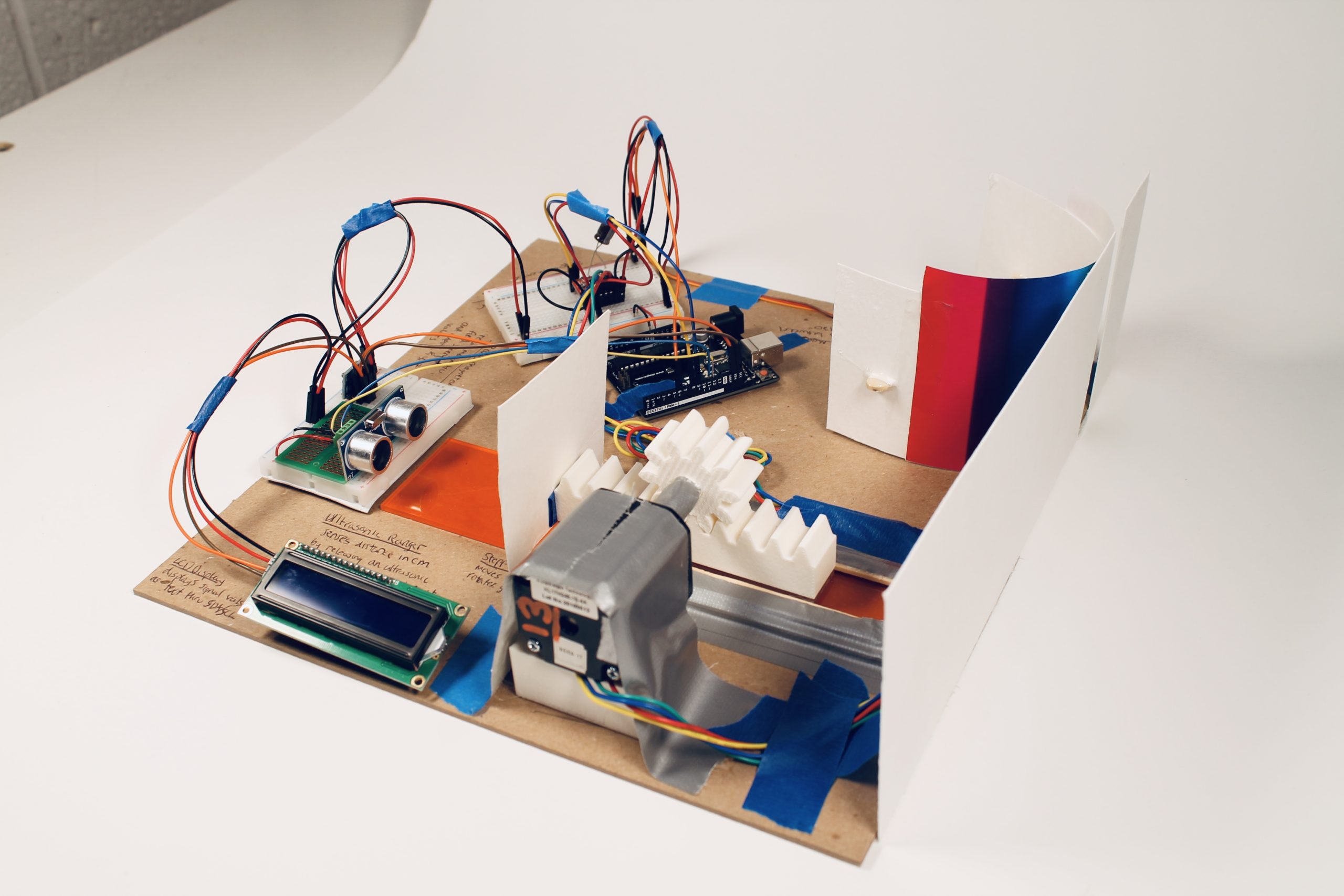
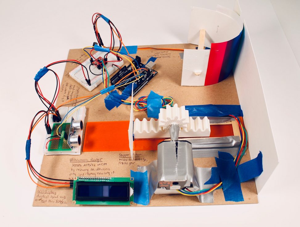
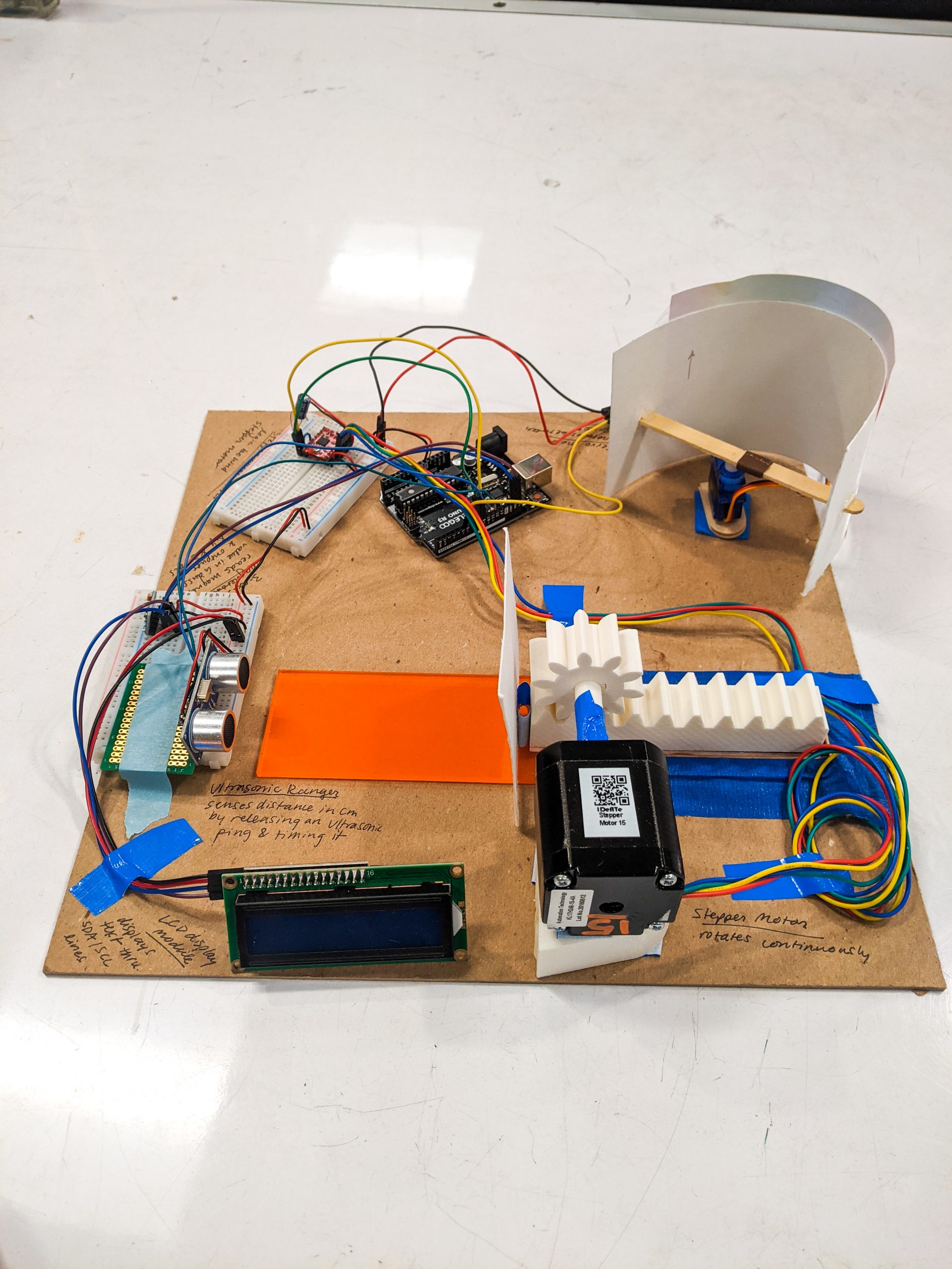
Overall Photo of Matthew’s Transducer
Overall photo of Shenai’s Transducer
Project Details
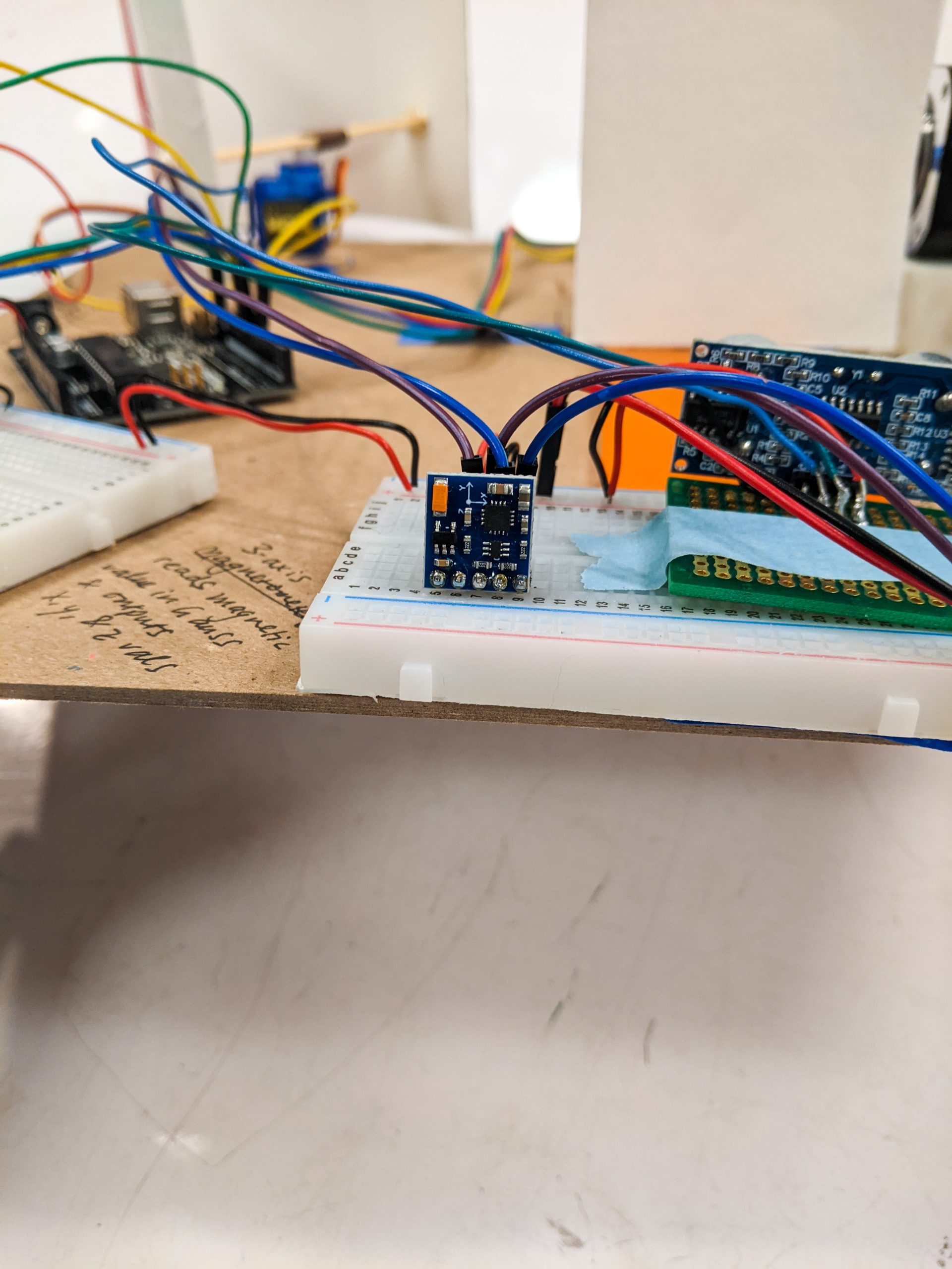
This three-axis magnetometer senses the strength of a magnetic field in 3 dimensions.
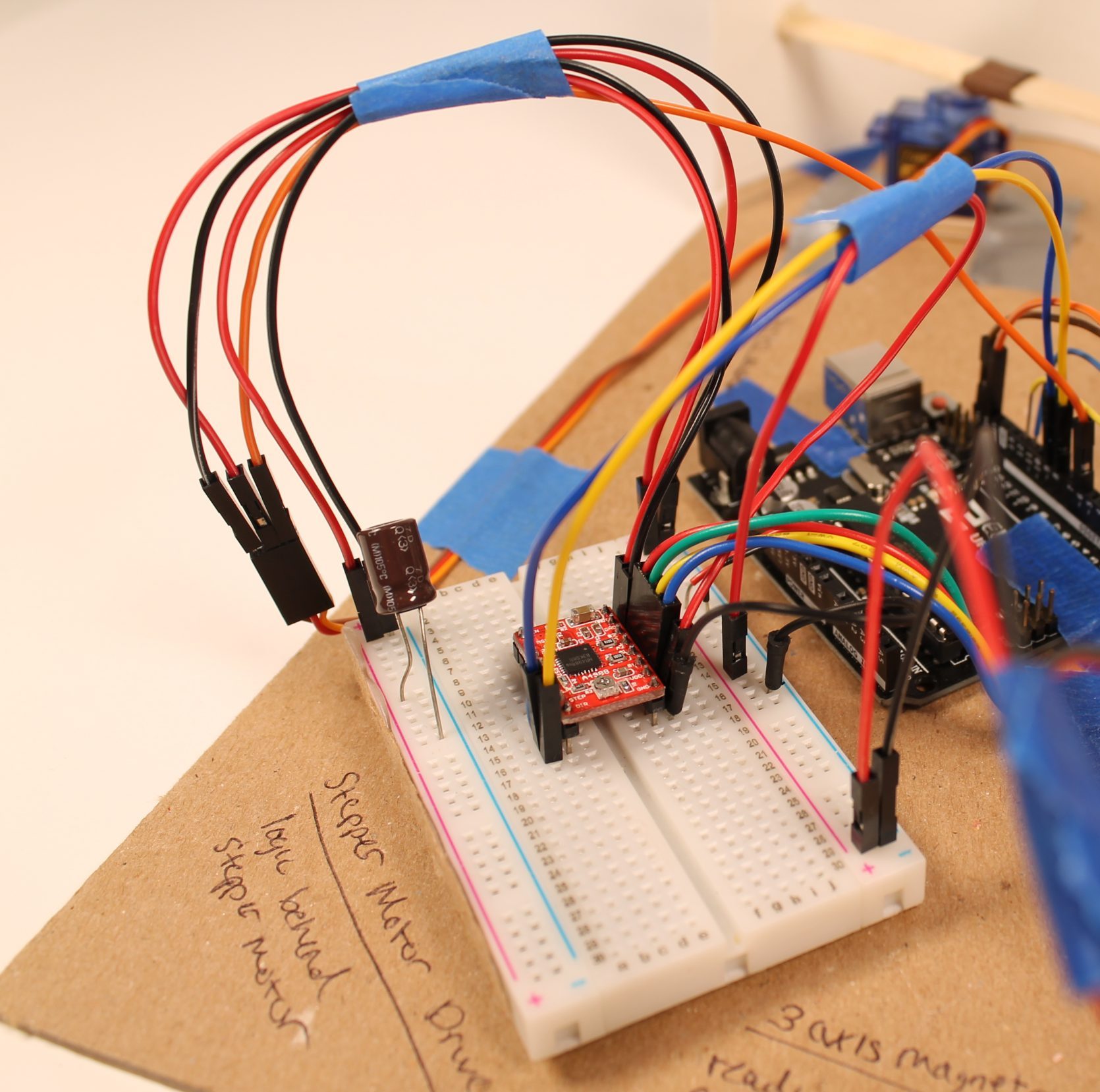
Shown is the Stepper Motor Driver. This provides the “brains” of the stepper, controlling direction, rotation angle and speed the motor rotates at.
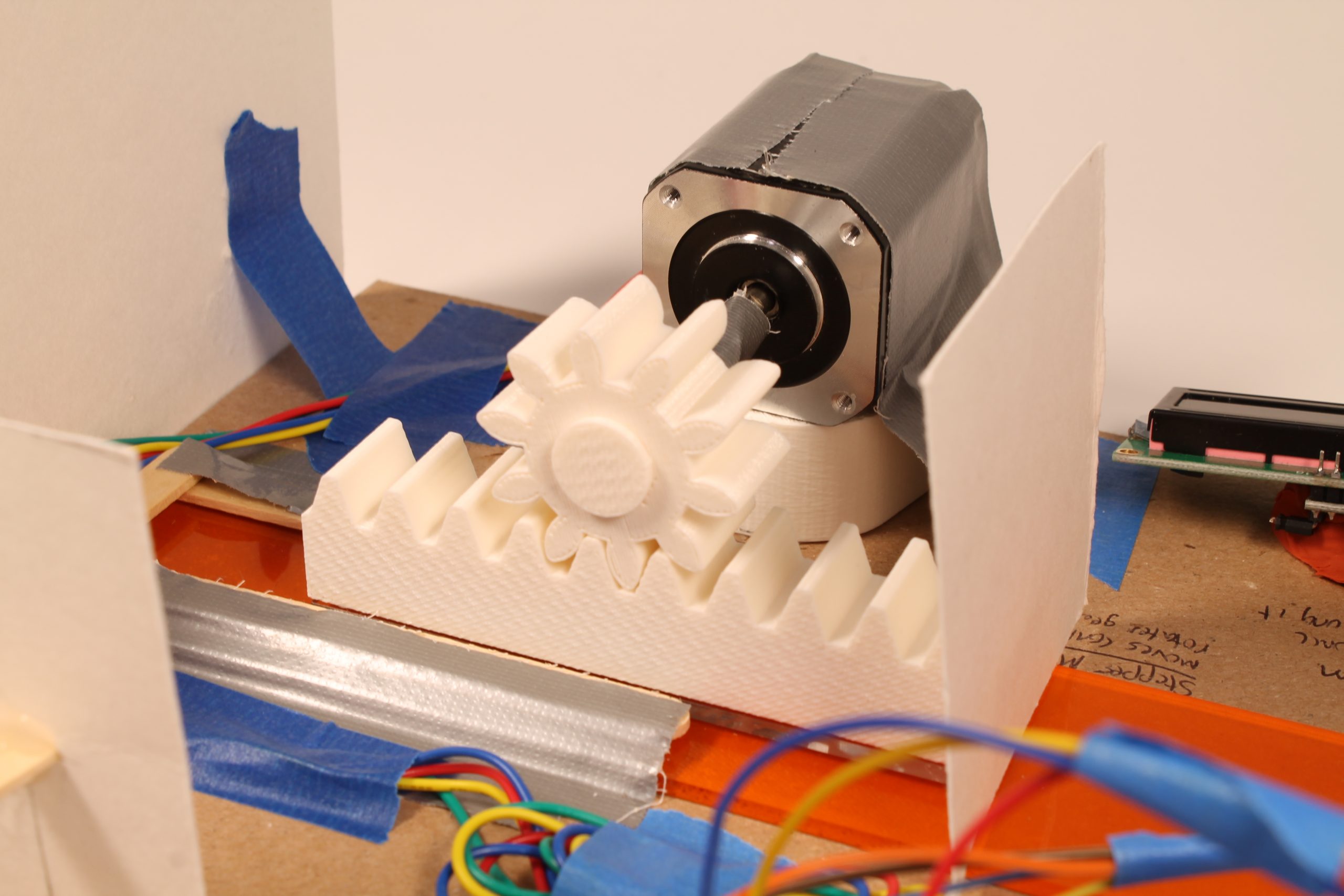
The Stepper Motor is attached to a rack and pinion system that slides back and forth depending on how strong the magnetic field is. The system slides on a piece of acrylic to reduce the kinetic friction between the 3-D printed material and the cardboard surface.
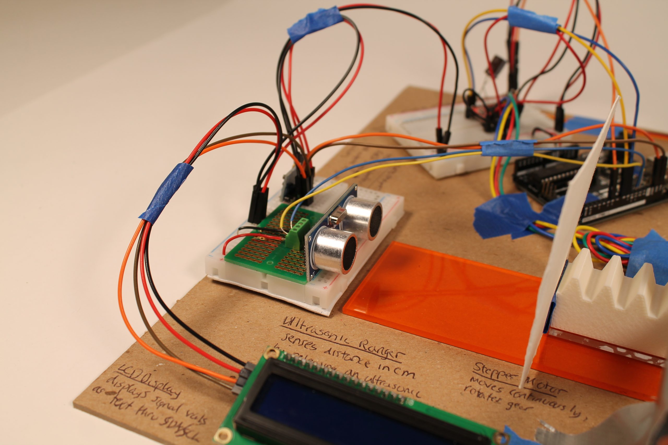
The Ultrasonic Ranger detects how far the rack is using sonar, and sends the signal back to the Arduino. The ranger is soldered to a soldering board with a screw terminal soldered on behind it, making it easy to connect wires since they don’t move around as our transducer is at work.
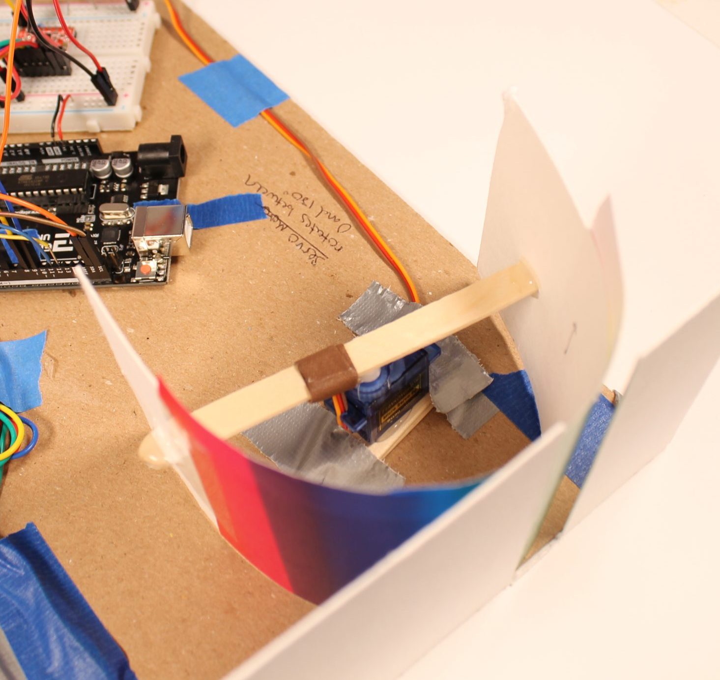
The Arduino maps the distance measurement to an angle and instructs the Servo Motor to rotate to the specific angle accordingly.
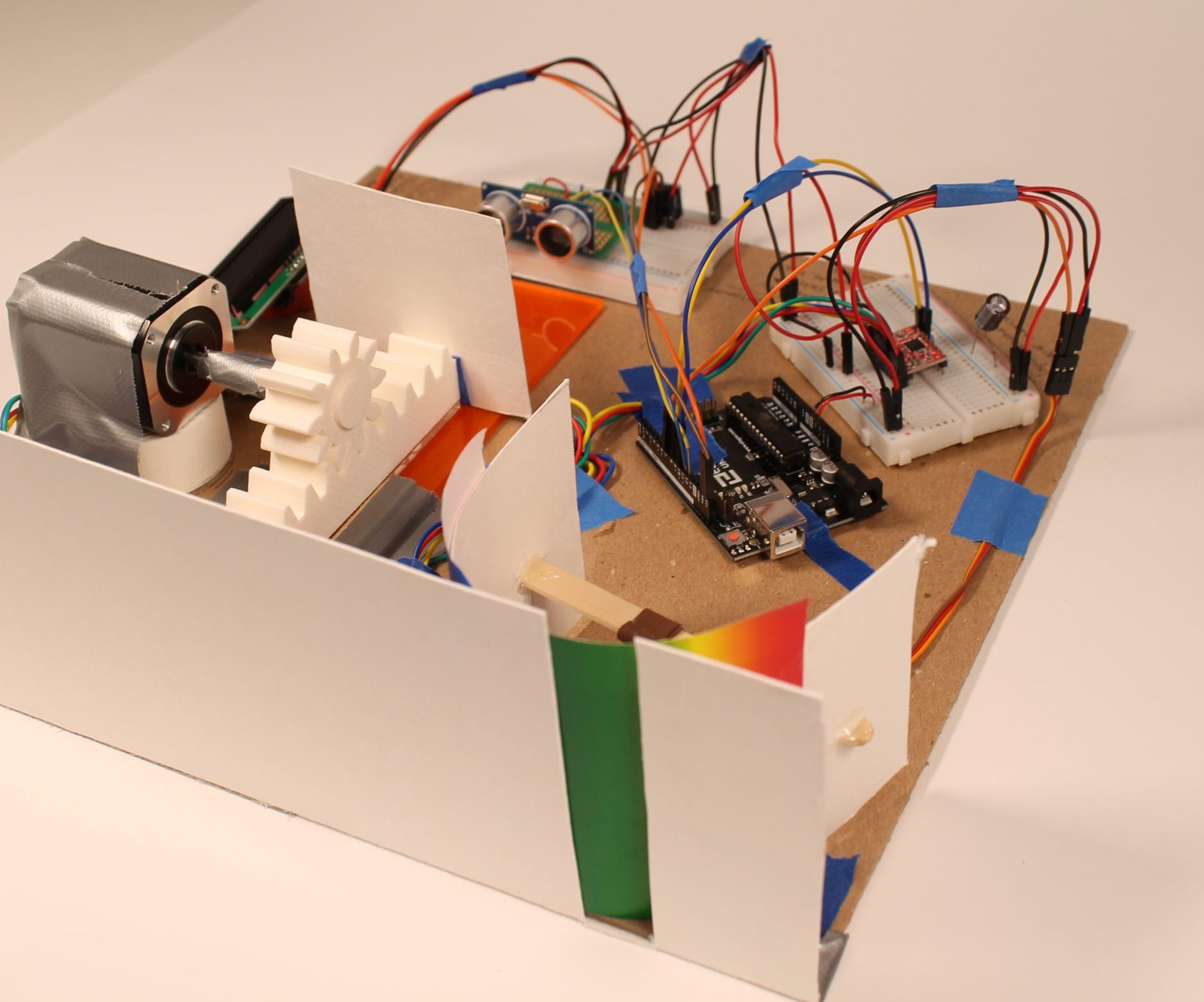
The rotation of the Servo Motor reveals a part of the color gradient as it rotates. This color output is then read by the next group’s transducer.
Project Video
Video Player00:0000:00
Project Description
We wanted to take input from the forces produced by a magnet, and give that information to a rotating motor. Then, the motor would rotate a gear, which would move a horizontal block with ridges that fit into the gear. We then sensed the position of the horizontal block, and then gave that information to another rotating motor. This second rotating motor was attached to a curved piece of paper, which had a range of colors on it. Our final output was the outward-facing color on the paper. All the information about positions and level of magnetic strength were printed as numbers on a screen for the viewer to see.
Progress Pictures
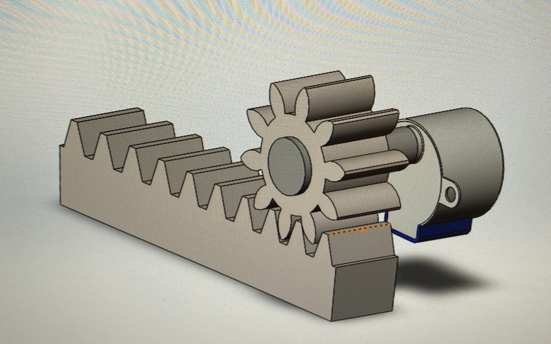
We used SolidWorks to model a rack and pinion we could 3-D print. The assembly was designed to move 1 cm for each 1/10th rotation of the motor, meaning the teeth on the rack are spread apart by 1 cm, the same measuring resolution as the ranger.
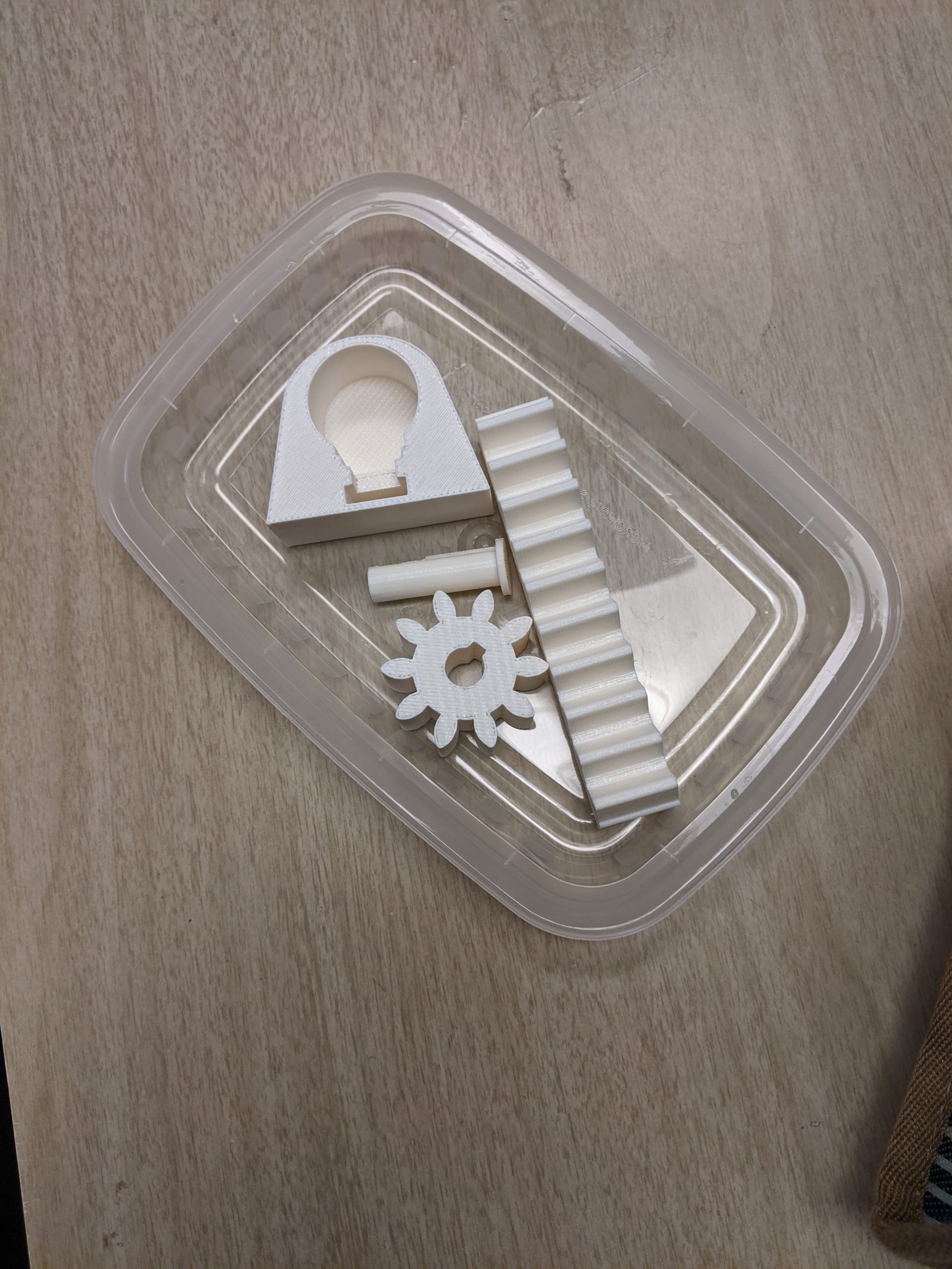
We utilized the IDEATE skylab to 3-D print the parts we needed for our project in a timely fashion.
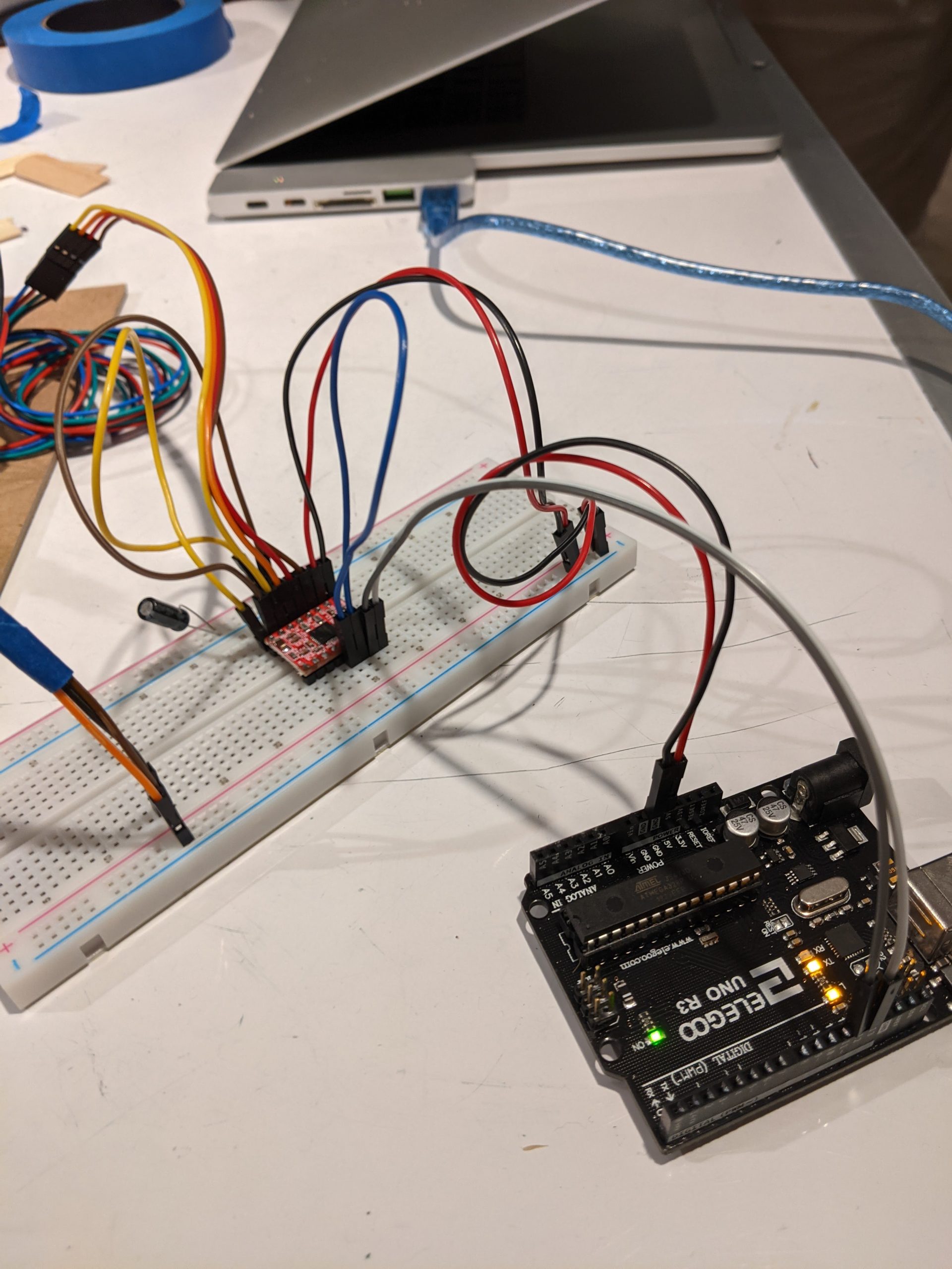
process stepper wiring, was wired to smaller motor so we had to redo
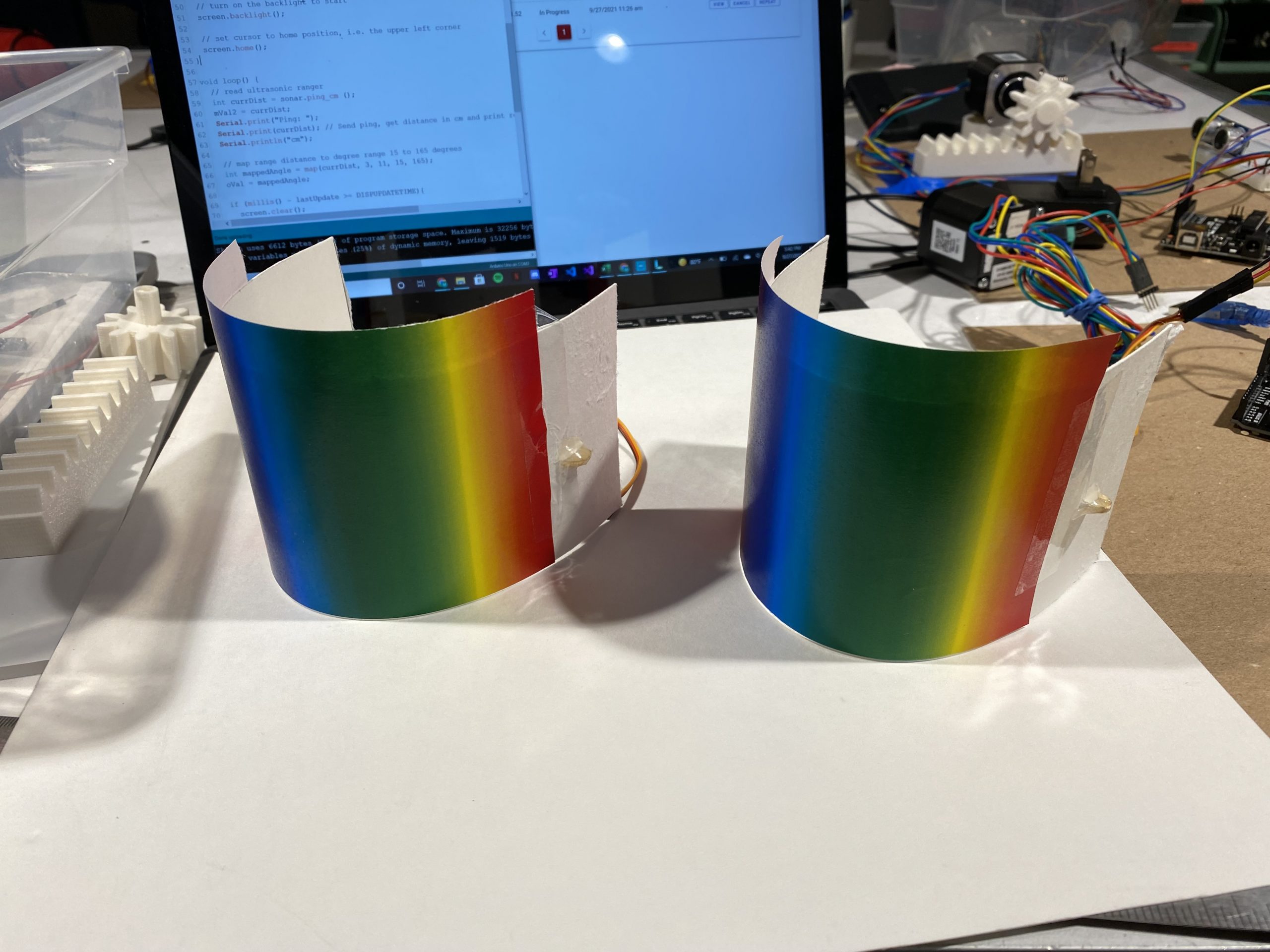
We created the printed color using a semi-cylinder with a color gradient surface. We used a popsicle stick as the axel so we could easily incorporate the servo motor into our design. We changed to a gradient from a rainbow pattern to allow us to print any hue value that the magnetic field strength is mapped to.
Discussion:
We both learned a lot from this process. We enjoyed teaming up together because we were equally invested in the success of the project, and because both had (semi-overlapping but still) different areas of technical expertise, which allowed us to synthesize knowledge from our respective fields. For example, Matthew is a Mechanical Engineering major and really good at CAD, so we were able to make quality, physical mechanisms within our middle step via our rack and pinion. Shenai is an Electrical and Computer Engineering major and she tackled a lot of the wiring and programming challenges.
Comments from Shenai: I enjoyed the team aspect of this project, as well as the hands-on quality of the work, which was something I had been lacking in my other classes. I also felt that I grew as a debugger, both in code and circuitry. It was really satisfying when I spotted that Matt’s stepper motor wasn’t properly grounded, and was able to fix it quickly. Another super satisfying moment was when I combined our separate code into a single file, very quickly checked for timing issues/duplicated pins and variables, and it compiled and ran perfectly on the first try.
However, we had a terrible time with the stepper motor. We had to go through 3 different chips and 2 motors, and we had to discard our custom-made 3-D print that housed the smaller motor because the smaller motor wouldn’t work properly with any of the chips. The 3-D print made us want to hang onto the smaller motor because we had already put so much time into setting up our machine specifically for it, but finally we ended up pivoting to the more powerful and reliable motor. I think if we had been more willing to pivot entirely instead of changing little things to fit our past decisions, we would have breezed through this process faster. Although, I will say, I got really fast at unwiring and rewiring various stepper motors and their drivers, so this iterative process was helpful for my technical growth in that respect.
Comments from Matthew: It was very exciting to have the opportunity to apply my knowledge of mechanical systems and CAD into this project. Despite having to change which stepper motor we used, the parts I created for the project all worked without the need for iterative design and further prototypes. This saved the course budget some money as we didn’t have to keep printing and printing more materials. Together, we were able to synthesize electrical and mechanical design in an effective and creative way to produce a successful end result. In addition to applying my Mechanical Engineering skills, I was able to learn a lot on the electrical side as well. I was able to brush up my coding skills in Arduino, become familiar with different electrical connections and sensors (magnetometer, ultrasonic ranger, stepper and servo motors, etc), and I even got to learn how to strip and solder wires for the first time. I feel that the acquisition of these new skills will help me grow as an engineer and will allow me to be more versatile in upcoming projects.
Functional Block Diagram
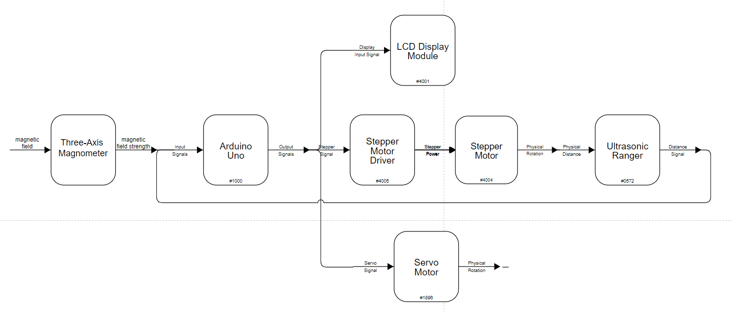
Functional Block Diagram of our Project using diagrams.net
Electric Schematic
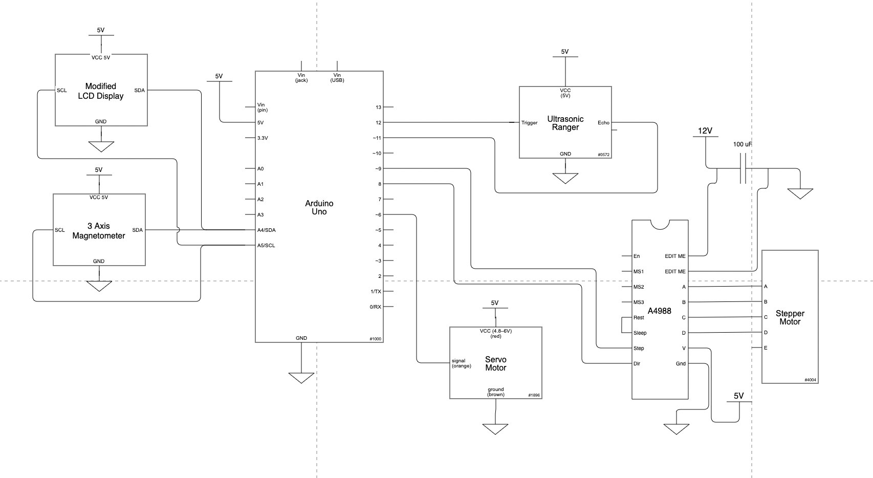
Electric Schematic for our project. We had access to a more simple LCD Display which allowed us to use SDA and SCL pins for both the magnetometer and the LCD display.
Code:
/** Magentic Field to Color Gradient Double Transducer** By: Matt Wagner and Shenai Chan** Desc: Takes in a reading of magnetic field strength,* converts it to rotational position on stepper motor,* uses Ultrasonic Ranger to sense the position of a* rack driver by the motor, feeds that information* to rotational position on a servo motor with substantial* delay to allow for proper reading of the servo position.* Sends input/output/intermediate information to an LCD display.** Pin mapping table:* SDA & SCL connected to both LCD and 3-axis magnetometer* 6 <-> servo* 8 <-> dir on stepper motor* 9 <-> step on stepper motor* 11 <-> echo on ultrasonic ranger* 12 <-> trig on uultrasonic ranger** Credit:* Referenced starter code by Robert Zacharias on timing signal sends;* instantiating USR, LCD, and servo; and writing to LCD.** https://courses.ideate.cmu.edu/60-223/f2021/tutorials/code-bites* https://courses.ideate.cmu.edu/60-223/f2021/tutorials/I2C-lcd** Referenced docs from Patrick Wasp's AccelStepper lib &* MPrograms' compass lib*//* First, import some libraries: */// I2C Library#include <Wire.h>// For the 3-axis magnetometer#include <QMC5883LCompass.h>// For the stepper motor#include <AccelStepper.h>// For the ultrasonic ranger#include <NewPing.h>// For the Servo Motor#include <Servo.h>// For the LCD display#include <LiquidCrystal_I2C.h>/* Then, instantiate objects that correlate to wired devices */// Make LCD objLiquidCrystal_I2C screen(0x27, 16, 2);int iVal;int mVal1;int mVal2;int oVal;// Make magnetometer objQMC5883LCompass compass;// Make stepper obj, as well as corresponding variables for waits// between writes, and keeping track of current position#define dirPin 8#define stepPin 9#define motorInterfaceType 1const int wait = 1000;long timer = 0;AccelStepper stepper = AccelStepper(motorInterfaceType, stepPin, dirPin);int currentPos;// Make USR obj#define TRIGGER_PIN 12#define ECHO_PIN 11#define MAX_DISTANCE 200NewPing sonar(TRIGGER_PIN, ECHO_PIN, MAX_DISTANCE);// Make servo objServo gaugeMotor;const int GAUGEMOTORPIN = 6;const unsigned long DISPUPDATETIME = 500;const unsigned long TIMEBETWEENREADS = 3000;unsigned long lastMove = millis();unsigned long lastUpdate = millis();void setup() {// Initialize the serial portSerial.begin(9600);// Initialize I2CWire.begin();// Initialize the servo motorgaugeMotor.attach(GAUGEMOTORPIN);// Initialize the magnetometercompass.init();// Initialize the stepper motorstepper.setCurrentPosition(0);stepper.setMaxSpeed(500);// Initialize the LCDscreen.init();// turn on the backlight to startscreen.backlight();// set cursor to home position, i.e. the upper left cornerscreen.home();}void loop() {// read ultrasonic rangerint currDist = sonar.ping_cm ();mVal2 = currDist;Serial.print("Ping: ");Serial.print(currDist); // Send ping, get distance in cm and print result (0 = outside set distance range)Serial.println("cm");// map range distance to degree range 15 to 165 degreesint mappedAngle = map(currDist, 3, 11, 15, 165);oVal = mappedAngle;// write to LCD with appropriate timingif (millis() - lastUpdate >= DISPUPDATETIME){screen.clear();screen.print("i:");screen.print(iVal);screen.setCursor(5, 0);screen.print("m:");screen.print(mVal1);screen.setCursor(7, 1);screen.print(mVal2);screen.setCursor(11, 1);screen.print("o:");screen.print(oVal);screen.home();lastUpdate = millis();}// write to servo with appropriate timingif (millis() - lastMove >= TIMEBETWEENREADS){// move motorif (mappedAngle >= 15 && mappedAngle <= 165){gaugeMotor.write(mappedAngle);lastMove = millis();}}// read from magnetometer and write to stepper with appropriate timingif ((millis() - timer) >= wait) {if (stepper.distanceToGo() == 0) {Serial.println("in if statement");int z;compass.read();z = compass.getZ();iVal = map(z, 0, 37000, 0, 99);Serial.println(z);int loc = map(z, 0, 37000, 0, -200);if (0 <= z && z <= 37000) {if (0 >= loc && loc > -50) {stepper.moveTo(0);}else if (-50 >= loc && loc > -100) {stepper.moveTo(-50);}else if (-100 >= loc && loc > -150) {stepper.moveTo(-100);}else if (-150 >= loc && loc >= -200) {stepper.moveTo(-150);}Serial.println(loc);stepper.setMaxSpeed(25);stepper.setAcceleration(25);timer = millis();mVal1 = map(z, 0, 37000, 0, 99);}}}stepper.run();}/* * Magentic Field to Color Gradient Double Transducer * * By: Matt Wagner and Shenai Chan * * Desc: Takes in a reading of magnetic field strength, * converts it to rotational position on stepper motor, * uses Ultrasonic Ranger to sense the position of a * rack driver by the motor, feeds that information * to rotational position on a servo motor with substantial * delay to allow for proper reading of the servo position. * Sends input/output/intermediate information to an LCD display. * * Pin mapping table: * SDA & SCL connected to both LCD and 3-axis magnetometer * 6 <-> servo * 8 <-> dir on stepper motor * 9 <-> step on stepper motor * 11 <-> echo on ultrasonic ranger * 12 <-> trig on uultrasonic ranger * * Credit: * Referenced starter code by Robert Zacharias on timing signal sends; * instantiating USR, LCD, and servo; and writing to LCD. * * https://courses.ideate.cmu.edu/60-223/f2021/tutorials/code-bites * https://courses.ideate.cmu.edu/60-223/f2021/tutorials/I2C-lcd * * Referenced docs from Patrick Wasp's AccelStepper lib & * MPrograms' compass lib */ /* First, import some libraries: */ // I2C Library #include <Wire.h> // For the 3-axis magnetometer #include <QMC5883LCompass.h> // For the stepper motor #include <AccelStepper.h> // For the ultrasonic ranger #include <NewPing.h> // For the Servo Motor #include <Servo.h> // For the LCD display #include <LiquidCrystal_I2C.h> /* Then, instantiate objects that correlate to wired devices */ // Make LCD obj LiquidCrystal_I2C screen(0x27, 16, 2); int iVal; int mVal1; int mVal2; int oVal; // Make magnetometer obj QMC5883LCompass compass; // Make stepper obj, as well as corresponding variables for waits // between writes, and keeping track of current position #define dirPin 8 #define stepPin 9 #define motorInterfaceType 1 const int wait = 1000; long timer = 0; AccelStepper stepper = AccelStepper(motorInterfaceType, stepPin, dirPin); int currentPos; // Make USR obj #define TRIGGER_PIN 12 #define ECHO_PIN 11 #define MAX_DISTANCE 200 NewPing sonar(TRIGGER_PIN, ECHO_PIN, MAX_DISTANCE); // Make servo obj Servo gaugeMotor; const int GAUGEMOTORPIN = 6; const unsigned long DISPUPDATETIME = 500; const unsigned long TIMEBETWEENREADS = 3000; unsigned long lastMove = millis(); unsigned long lastUpdate = millis(); void setup() { // Initialize the serial port Serial.begin(9600); // Initialize I2C Wire.begin(); // Initialize the servo motor gaugeMotor.attach(GAUGEMOTORPIN); // Initialize the magnetometer compass.init(); // Initialize the stepper motor stepper.setCurrentPosition(0); stepper.setMaxSpeed(500); // Initialize the LCD screen.init(); // turn on the backlight to start screen.backlight(); // set cursor to home position, i.e. the upper left corner screen.home(); } void loop() { // read ultrasonic ranger int currDist = sonar.ping_cm (); mVal2 = currDist; Serial.print("Ping: "); Serial.print(currDist); // Send ping, get distance in cm and print result (0 = outside set distance range) Serial.println("cm"); // map range distance to degree range 15 to 165 degrees int mappedAngle = map(currDist, 3, 11, 15, 165); oVal = mappedAngle; // write to LCD with appropriate timing if (millis() - lastUpdate >= DISPUPDATETIME){ screen.clear(); screen.print("i:"); screen.print(iVal); screen.setCursor(5, 0); screen.print("m:"); screen.print(mVal1); screen.setCursor(7, 1); screen.print(mVal2); screen.setCursor(11, 1); screen.print("o:"); screen.print(oVal); screen.home(); lastUpdate = millis(); } // write to servo with appropriate timing if (millis() - lastMove >= TIMEBETWEENREADS){ // move motor if (mappedAngle >= 15 && mappedAngle <= 165){ gaugeMotor.write(mappedAngle); lastMove = millis(); } } // read from magnetometer and write to stepper with appropriate timing if ((millis() - timer) >= wait) { if (stepper.distanceToGo() == 0) { Serial.println("in if statement"); int z; compass.read(); z = compass.getZ(); iVal = map(z, 0, 37000, 0, 99); Serial.println(z); int loc = map(z, 0, 37000, 0, -200); if (0 <= z && z <= 37000) { if (0 >= loc && loc > -50) { stepper.moveTo(0); } else if (-50 >= loc && loc > -100) { stepper.moveTo(-50); } else if (-100 >= loc && loc > -150) { stepper.moveTo(-100); } else if (-150 >= loc && loc >= -200) { stepper.moveTo(-150); } Serial.println(loc); stepper.setMaxSpeed(25); stepper.setAcceleration(25); timer = millis(); mVal1 = map(z, 0, 37000, 0, 99); } } } stepper.run(); }/* * Magentic Field to Color Gradient Double Transducer * * By: Matt Wagner and Shenai Chan * * Desc: Takes in a reading of magnetic field strength, * converts it to rotational position on stepper motor, * uses Ultrasonic Ranger to sense the position of a * rack driver by the motor, feeds that information * to rotational position on a servo motor with substantial * delay to allow for proper reading of the servo position. * Sends input/output/intermediate information to an LCD display. * * Pin mapping table: * SDA & SCL connected to both LCD and 3-axis magnetometer * 6 <-> servo * 8 <-> dir on stepper motor * 9 <-> step on stepper motor * 11 <-> echo on ultrasonic ranger * 12 <-> trig on uultrasonic ranger * * Credit: * Referenced starter code by Robert Zacharias on timing signal sends; * instantiating USR, LCD, and servo; and writing to LCD. * * https://courses.ideate.cmu.edu/60-223/f2021/tutorials/code-bites * https://courses.ideate.cmu.edu/60-223/f2021/tutorials/I2C-lcd * * Referenced docs from Patrick Wasp's AccelStepper lib & * MPrograms' compass lib */ /* First, import some libraries: */ // I2C Library #include <Wire.h> // For the 3-axis magnetometer #include <QMC5883LCompass.h> // For the stepper motor #include <AccelStepper.h> // For the ultrasonic ranger #include <NewPing.h> // For the Servo Motor #include <Servo.h> // For the LCD display #include <LiquidCrystal_I2C.h> /* Then, instantiate objects that correlate to wired devices */ // Make LCD obj LiquidCrystal_I2C screen(0x27, 16, 2); int iVal; int mVal1; int mVal2; int oVal; // Make magnetometer obj QMC5883LCompass compass; // Make stepper obj, as well as corresponding variables for waits // between writes, and keeping track of current position #define dirPin 8 #define stepPin 9 #define motorInterfaceType 1 const int wait = 1000; long timer = 0; AccelStepper stepper = AccelStepper(motorInterfaceType, stepPin, dirPin); int currentPos; // Make USR obj #define TRIGGER_PIN 12 #define ECHO_PIN 11 #define MAX_DISTANCE 200 NewPing sonar(TRIGGER_PIN, ECHO_PIN, MAX_DISTANCE); // Make servo obj Servo gaugeMotor; const int GAUGEMOTORPIN = 6; const unsigned long DISPUPDATETIME = 500; const unsigned long TIMEBETWEENREADS = 3000; unsigned long lastMove = millis(); unsigned long lastUpdate = millis(); void setup() { // Initialize the serial port Serial.begin(9600); // Initialize I2C Wire.begin(); // Initialize the servo motor gaugeMotor.attach(GAUGEMOTORPIN); // Initialize the magnetometer compass.init(); // Initialize the stepper motor stepper.setCurrentPosition(0); stepper.setMaxSpeed(500); // Initialize the LCD screen.init(); // turn on the backlight to start screen.backlight(); // set cursor to home position, i.e. the upper left corner screen.home(); } void loop() { // read ultrasonic ranger int currDist = sonar.ping_cm (); mVal2 = currDist; Serial.print("Ping: "); Serial.print(currDist); // Send ping, get distance in cm and print result (0 = outside set distance range) Serial.println("cm"); // map range distance to degree range 15 to 165 degrees int mappedAngle = map(currDist, 3, 11, 15, 165); oVal = mappedAngle; // write to LCD with appropriate timing if (millis() - lastUpdate >= DISPUPDATETIME){ screen.clear(); screen.print("i:"); screen.print(iVal); screen.setCursor(5, 0); screen.print("m:"); screen.print(mVal1); screen.setCursor(7, 1); screen.print(mVal2); screen.setCursor(11, 1); screen.print("o:"); screen.print(oVal); screen.home(); lastUpdate = millis(); } // write to servo with appropriate timing if (millis() - lastMove >= TIMEBETWEENREADS){ // move motor if (mappedAngle >= 15 && mappedAngle <= 165){ gaugeMotor.write(mappedAngle); lastMove = millis(); } } // read from magnetometer and write to stepper with appropriate timing if ((millis() - timer) >= wait) { if (stepper.distanceToGo() == 0) { Serial.println("in if statement"); int z; compass.read(); z = compass.getZ(); iVal = map(z, 0, 37000, 0, 99); Serial.println(z); int loc = map(z, 0, 37000, 0, -200); if (0 <= z && z <= 37000) { if (0 >= loc && loc > -50) { stepper.moveTo(0); } else if (-50 >= loc && loc > -100) { stepper.moveTo(-50); } else if (-100 >= loc && loc > -150) { stepper.moveTo(-100); } else if (-150 >= loc && loc >= -200) { stepper.moveTo(-150); } Serial.println(loc); stepper.setMaxSpeed(25); stepper.setAcceleration(25); timer = millis(); mVal1 = map(z, 0, 37000, 0, 99); } } } stepper.run(); }