Alice’s Board

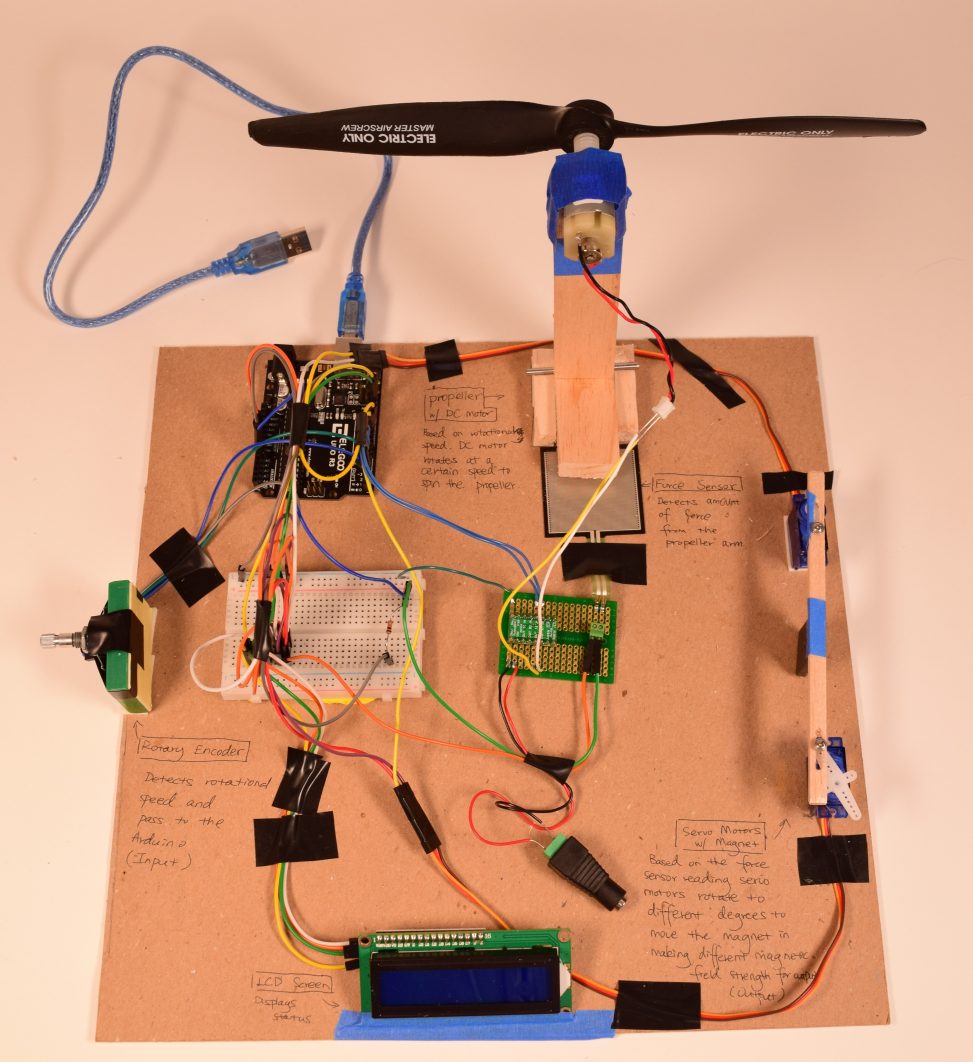
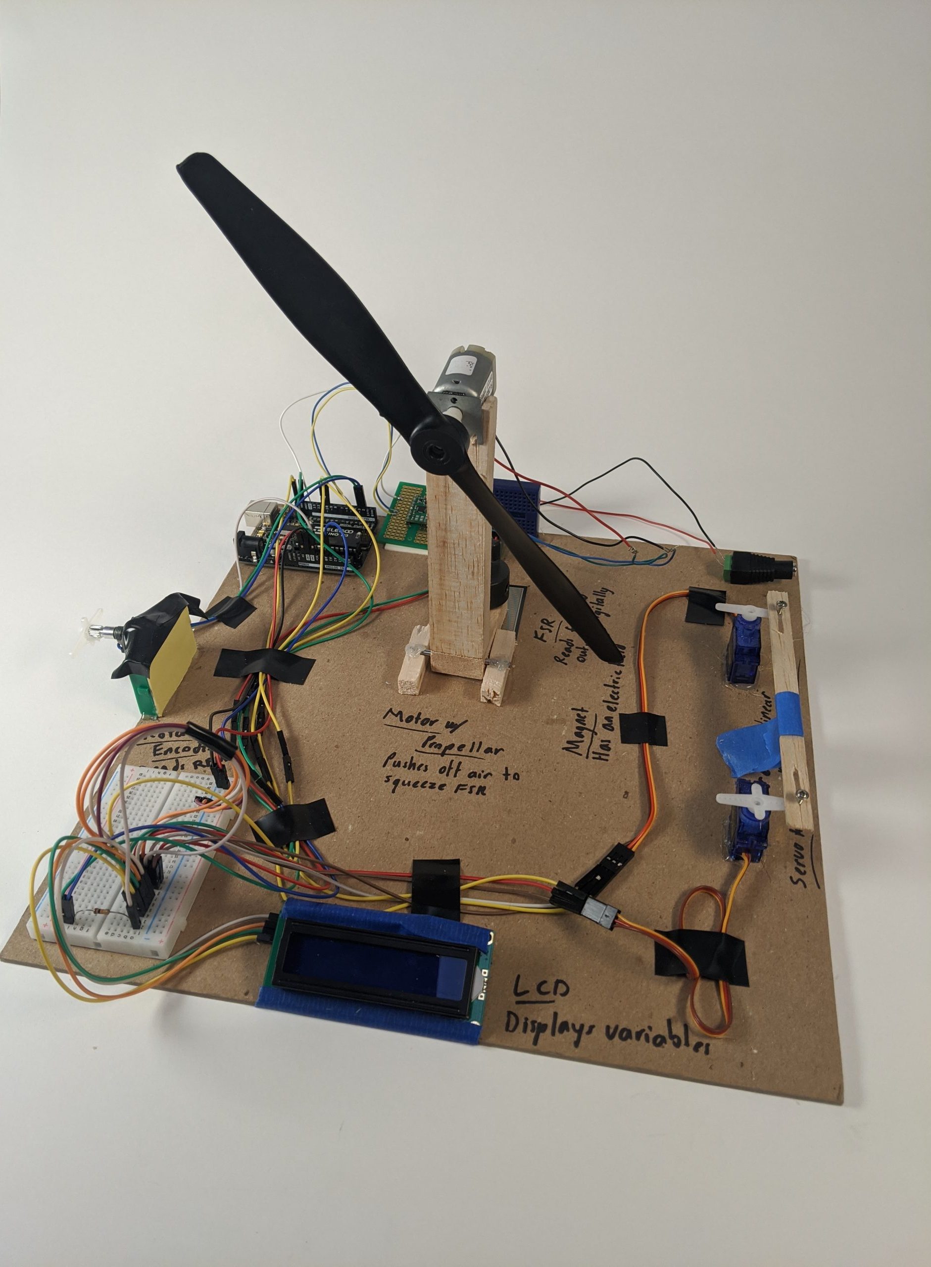
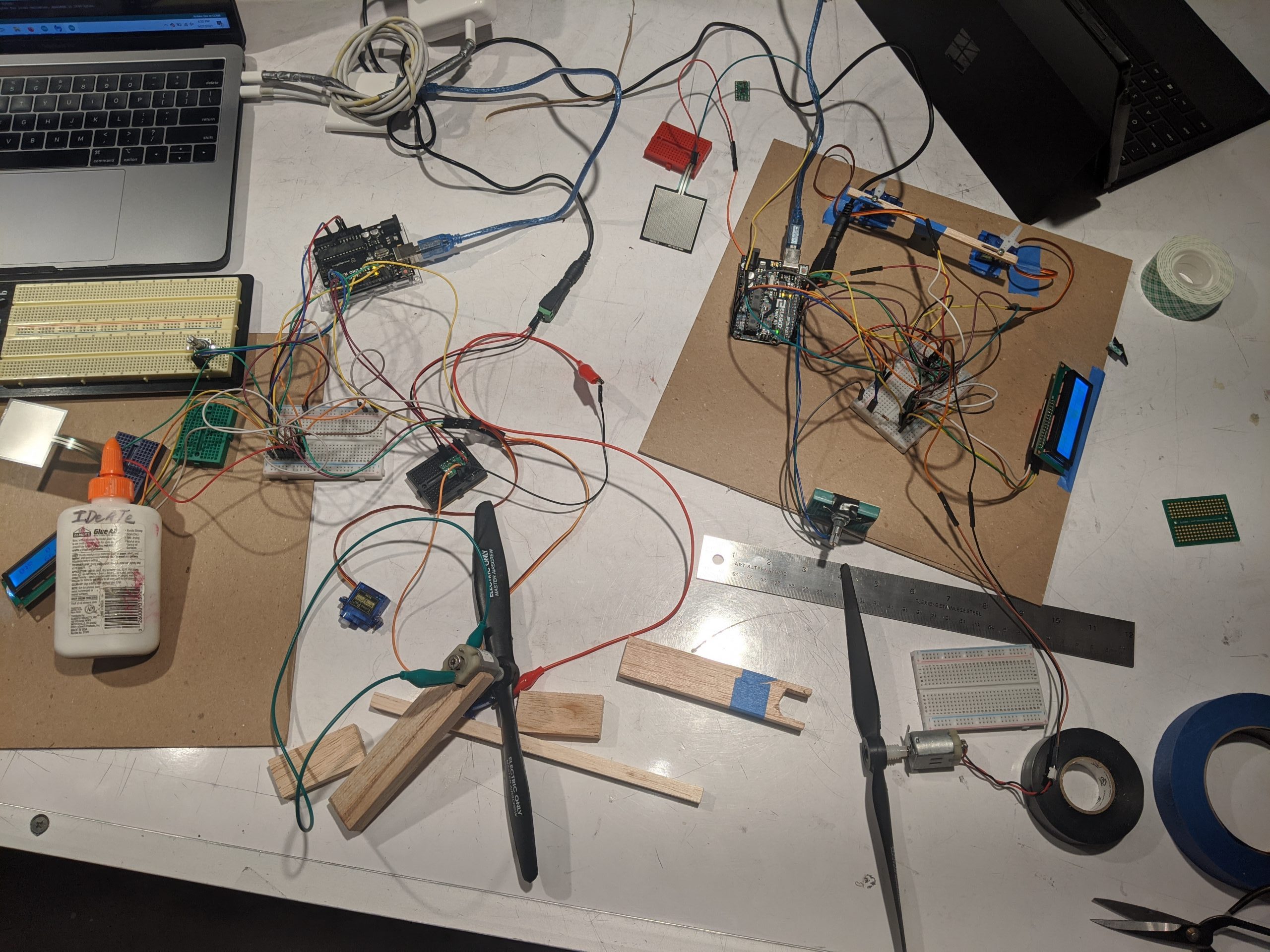
Overall photo
Video of working machine: when rotational speed is at its highest, the propeller spins fast and presses down on the force sensor a lot, which translates to the maximum rotation of servo motors bringing the magnet all the way to the right edge of the board.
Detail photos of parts
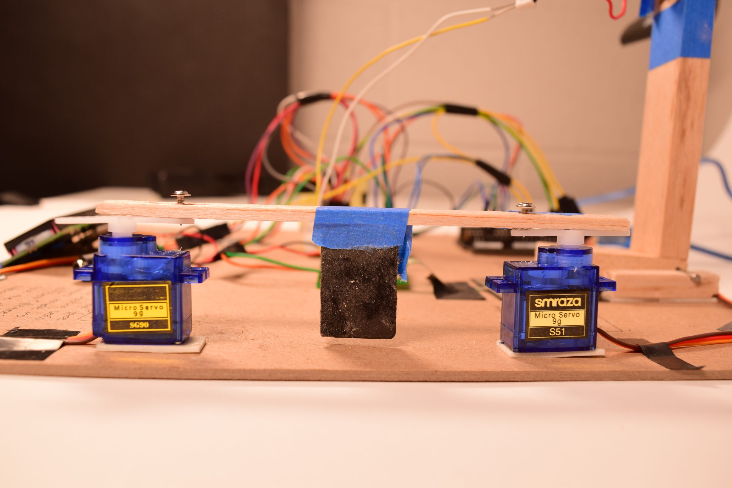
Servo motors holding the magnet (our output)
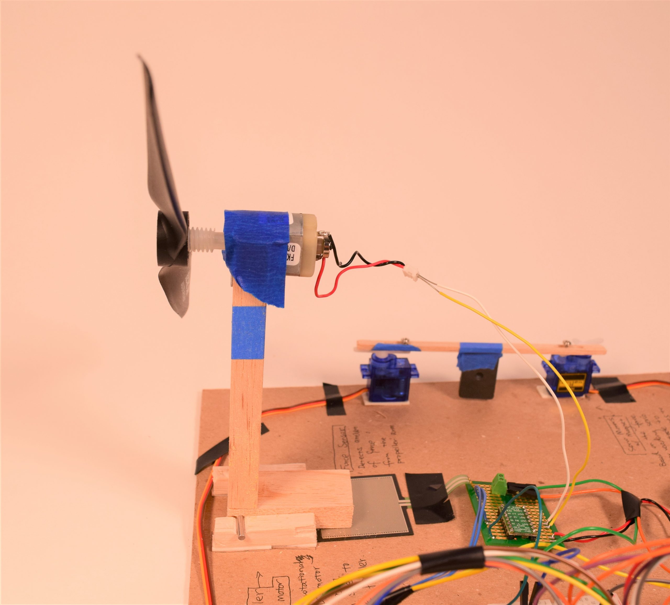
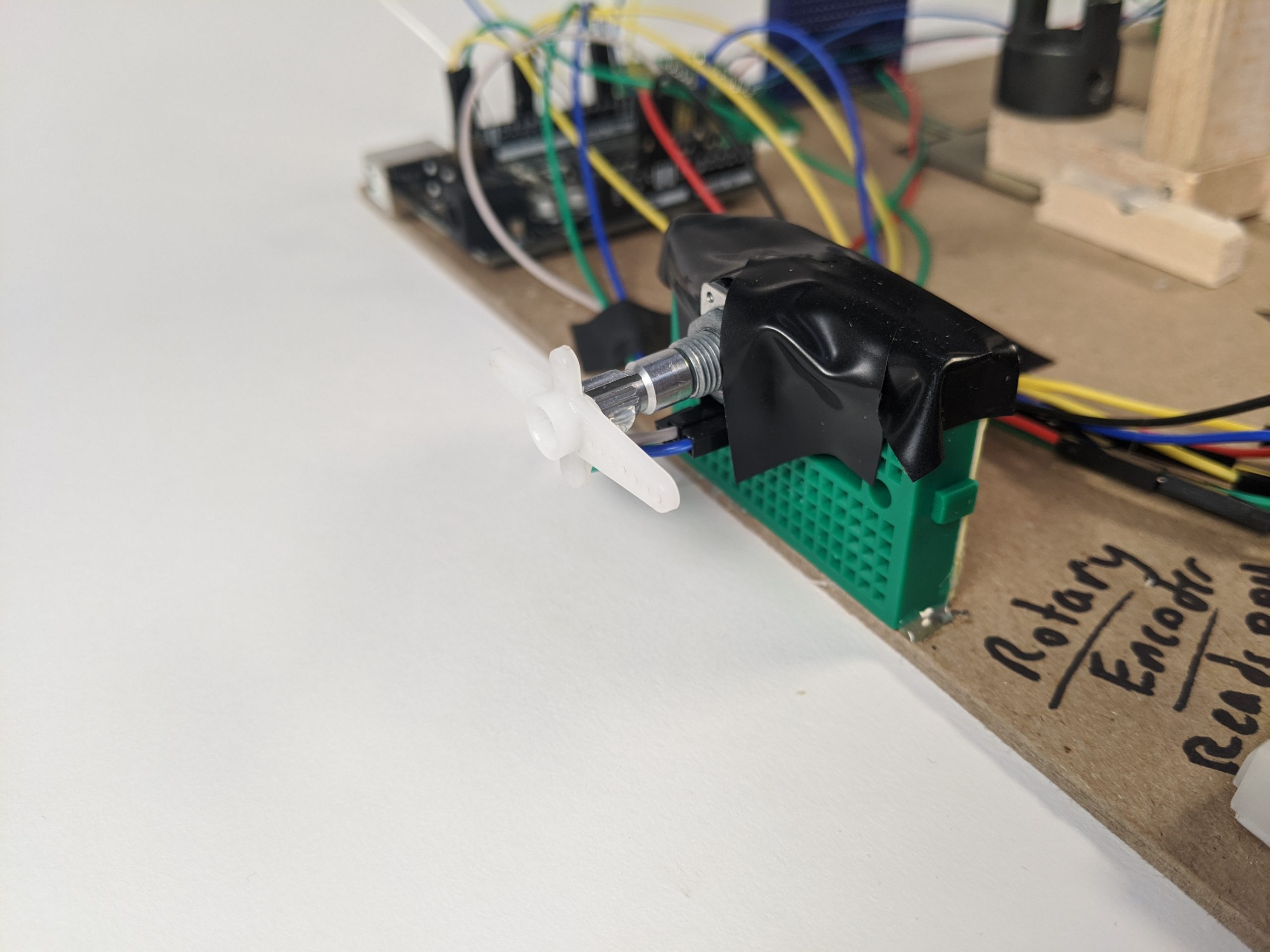
Propeller connected to a DC motor, standing upright with force sensor at the bottom of the propeller arm (our middle step)
Noel’s Board
Video
The encoder constantly samples rotational speed and determines the voltage passed on to the motor. The greater force translates across the FSR and is translated into servo position. Jittery human input produces similarly jittery magnet position.
Detail photos of parts
Our solution to the servo-encoder interface between projects, featuring hot glue and luck
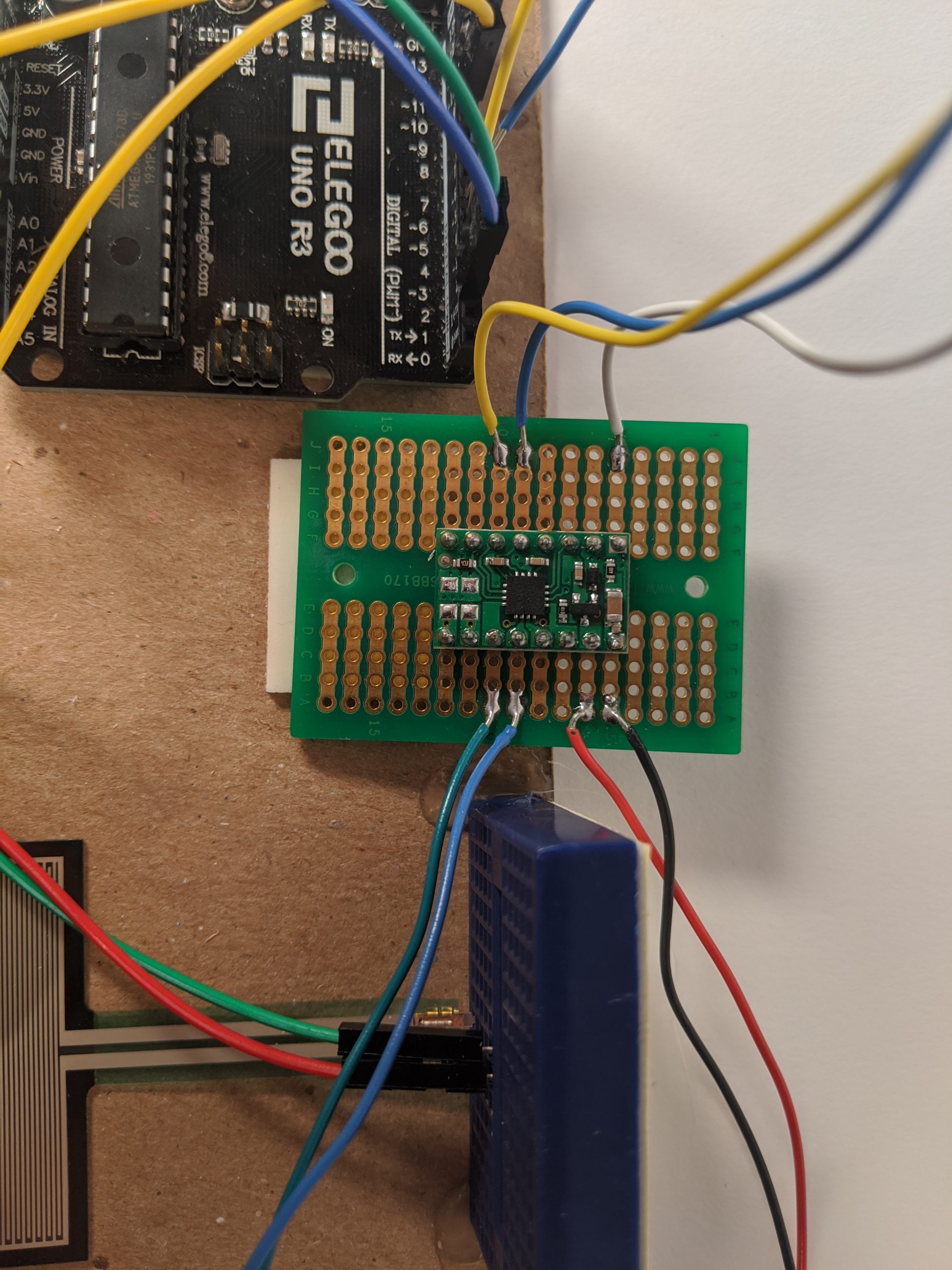
The DRV8833, the chip that allows us to drive the DC motor with more than on and off
Narrative Description:
Our input is rotational speed. That is measured by how fast the knob (rotary encoder) gets turned at the left of our boards. This rotational speed is then used to calculate how fast we turn our DC motor, which is connected to a propeller. The propeller sits upright in the middle of our board and it is built in a way so that depending on the spinning speed, the propeller arm tilts in differing amounts to press onto the square force sensor resistor at the bottom. Based on the force reading, degree of rotation for the servo motors are determined. The servos are holding a piece of magnet and greater rotation equals to further distance of the magnet to the next team’s board. With different distances, we create different strengths of magnetic field which is our output.
Progress Images:
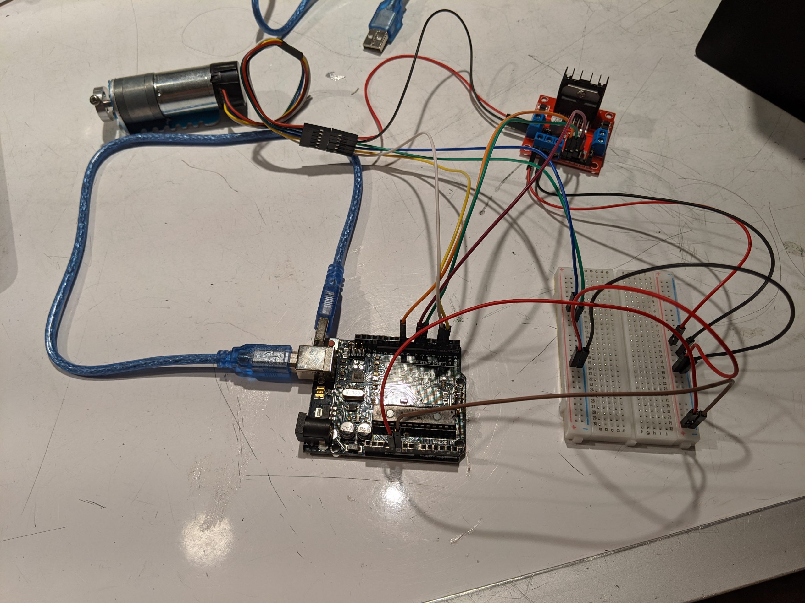
An early mock up of the motor wiring. Using a motor with an encoder and voltage regulator board. Replaced by simple motor and motor driver.
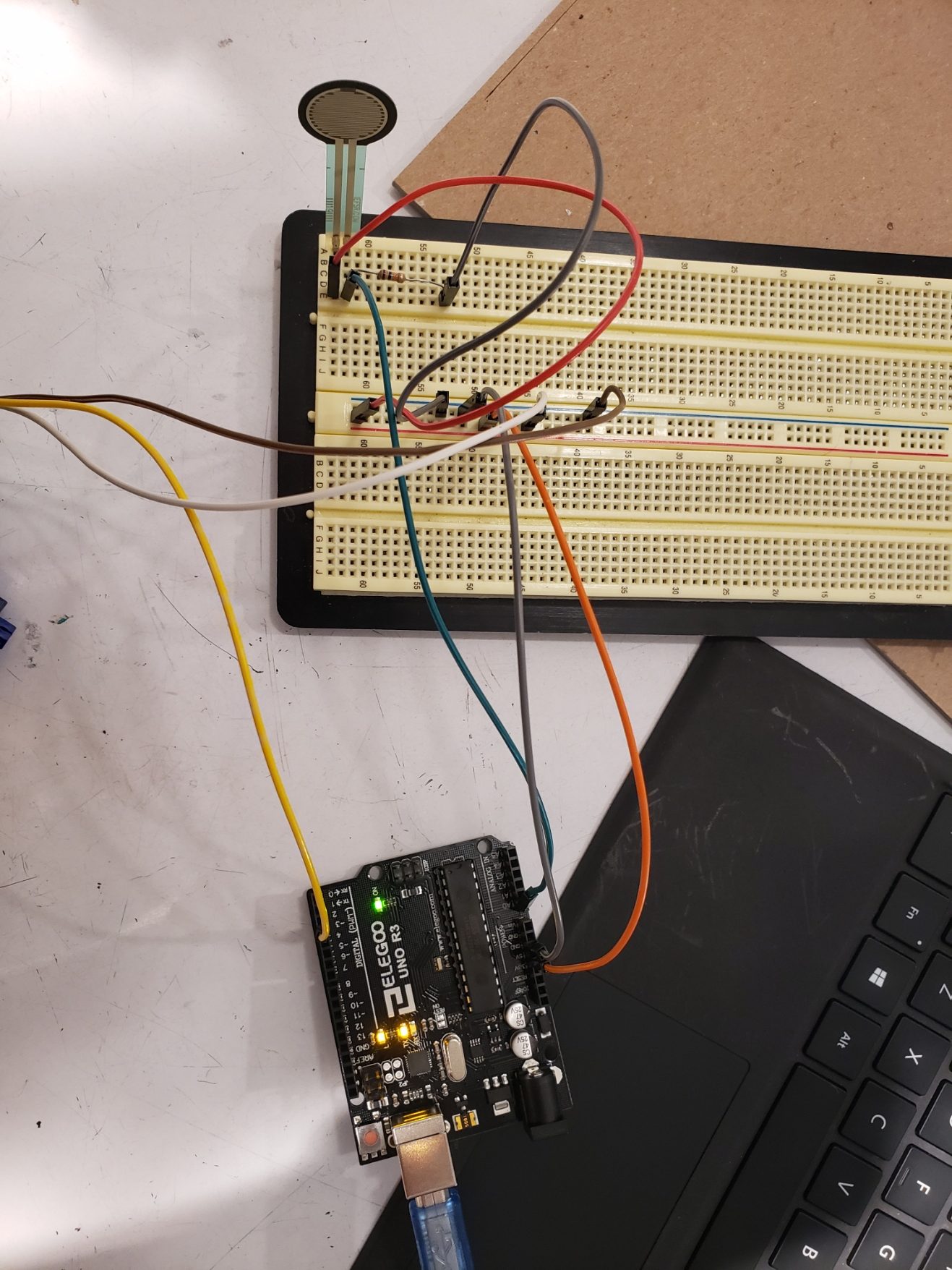
Force Sensor Testing: wiring up the fsr to see how it reads by making it print in Serial Monitor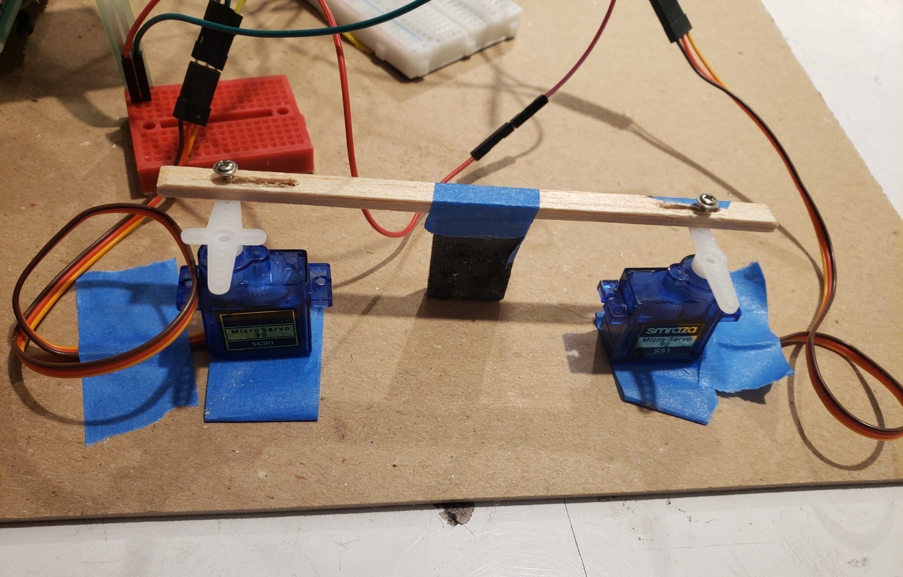 Testing out the positions of servo motors. This was a critical step as we changed from our original design of using rubber bands arms sliding the magnet along a track to using a rigid arm.
One of the final troubleshooting phases. After re-seating every cable and testing every sensor, an incompatible power supply was the culprit.
Discussion:
The development of this project was a rollercoaster. Initial ambitions were blinding and made issues very easy to overlook, and there were several that we did. We made two simple backups and spent all of our creative power on integrating a windmill. We easily overlooked issues like creating linear motion with servos, balancing and connecting a propeller, and the interface between encoder and previous project’s servo. Our imagined outcome was not adherent to all the real physical limitations, and this would be apparent when we tried to share ideas. Solidworks, hand drawings, and real physical progress ultimately bridged the gap between the imagined and the real.
Through our build we were constantly reminded of the many tools that had already been developed before us. In an attempt to use as powerful a motor as we could find, we showed our lack of intuition for thrust and knowledge of available parts. Thanks to our professor, online resources, and physical testing, we derived something efficient and conceivable. These resources were invaluable, as neither of us had any idea a DRV8833 (dual motor driver carrier) was an available tool. Peers also helped ideation, and the learning environment was a significant help in understanding what we could accomplish. Miniature breadboards and switching to square FSRs were two results of the vibrant learning environment.
One of the most frustrating steps was connecting libraries and pre-existing code with our own. From completely unresponsive to mapped and tuned scaling, the troubleshooting often involved scrapping entire drafts and scouring for relevant sample code. Here it was obvious that we were “standing on the shoulders of giants.” With documentation from the course webpage and from online users with valuable experience with each part, we had plenty of comments to read and build our understanding of how we could connect each sensor and output device. Despite the plethora of technical documentation, we still sometimes found ourselves adjusting parameters through trial and error. In combining available resources and first hand experience, we were able to develop the system we imagined.
Functional Block Diagram:

Schematic:

Code:
/*Project Title: Double Transducer: Rotational Speed -> Magnetic Field Strength
  Team Members: Noel Barnes, Yuqi (Alice) Zhou
  Description: Arduino takes in input from a rotary encode to calculate the rotational speed.
             This speed is then mapped into a speed that's feed into the DC motor to drive a propeller.
             FSR then picks up a force reading from the tilt of the Propeller arm.
             The force reading is then mapped to a rotation degree for the servo motor.
             Servo motors are moved based on the rotation to move the magentic forward.
  Pin mapping:
    Arduino pin | role   | description
    ------------|--------|-------------
    A0            input     FSR for force sensing
    2             input     rotary encoder pin A
    3             input     rotary encoder pin B
    5             input     drv8833 A2 IN
    6             input     drv8833 A1 IN
    10            output    servo motor #1
    11            output    servo motor #2
    SCL                     SCL of LCD
    SDA                     SDA of LCD

  Rotoray Encoder Code adapted from https://dronebotworkshop.com/rotary-encoders-arduino/#Arduino_Motor_Encoder_Sketch DroneBot Workshop 2019
  DC motor code adapted from https://courses.ideate.cmu.edu/16-223/f2016/text/lib/WheelDrive.html#wheeldrive-doxygen
*/

#include <Servo.h>
#include <Wire.h>
#include <LiquidCrystal_I2C.h>

LiquidCrystal_I2C screen(0x27, 16, 2);

// Motor encoder output pulse per rotation (change as required)
#define ENC_COUNT_REV 374

// Encoder output to Arduino Interrupt pin
#define ENC_IN 3

// Pulse count from encoder
volatile long encoderValue = 0;

// interval for measurements of rotational speed
int interval = 100;
const int quaterSec = 250;
unsigned long timer = 0;
long previousMillis = 0;
long currentMillis = 0;

int rpm = 0;
int rpmDisplay; // RPM display for the LCD screen
int motorRPM; // DC motor speed
int dcDisplay; // DC motor speed display for LCD screen

//make a servo object
Servo lilMotor;
Servo secMotor;
const int LILMOTORPIN = 11; // Servo Motor to pin 11
const int SECMOTORPIN = 10; // Servo Motor to pin 10

int force; // the analog reading from the FSR
int forceDisplay; // force display for the LDC screen
int fsrPin = 0;     // the FSR and 10K pulldown are connected to a0

int rotation; // rotation degree for lilMotor
int rotationTwo; // rotation degree for secMotor
int rotationDisplay; // servo motor rotation display for LDC screen

#define A1PIN 6
#define A2PIN 5

void setup() {
  // Set encoder as input with internal pullup
  pinMode(ENC_IN, INPUT_PULLUP);
  // Attach interrupt
  attachInterrupt(digitalPinToInterrupt(ENC_IN), updateEncoder, RISING);
  // Setup initial values for timer
  previousMillis = millis();

  // initialize DC motor
  pinMode(A1PIN, OUTPUT);
  pinMode(A2PIN, OUTPUT);
  digitalWrite(A1PIN, LOW);
  digitalWrite(A2PIN, LOW);

  // tell Arduino where the servo motors are plugged in
  lilMotor.attach(LILMOTORPIN);
  secMotor.attach(SECMOTORPIN);
  // initialize the screen (only need to do this once)
  screen.init();
  // turn on the backlight to start
  screen.backlight();

  // lcd display template
  screen.home();
  screen.print("i:");
  screen.setCursor(6, 0);
  screen.print("m:");
  screen.setCursor(12, 1);
  screen.print("o:");

}

void loop() {
  // Update RPM value
  currentMillis = millis();
  if (currentMillis - previousMillis > interval) {
    previousMillis = currentMillis;
    // Calculate RPM
    rpm = (float)(encoderValue * 60 / ENC_COUNT_REV);
    //follow the range of 20-60 for rotational speed
    if (rpm > 60) {
      rpm = 60;
    }
    if (rpm < 20) {
      rpm = 20;
    }
    encoderValue = 0;
  }
  //rotational speed display
  if (millis() - timer >= quaterSec) {
    screen.setCursor(2, 0);
    rpmDisplay = map(rpm, 20, 60, 0, 99);
    screen.print(rpmDisplay);
  }

  // run DC motor with RPM
  motorRPM = map(rpm, 20 , 60, 80, 255); //normalize rotational speed to input as DC motor speed
  digitalWrite(A1PIN, LOW);
  analogWrite(A2PIN, motorRPM);
  delay(2);

  // DC motor speed display
  if (millis() - timer >= quaterSec) {
    screen.setCursor(8, 0);
    dcDisplay = map(motorRPM, 80, 255, 0, 99); // normalized for display
    screen.print(dcDisplay);
  }


  // force reading
  force = analogRead(fsrPin);
  // limit to a force range that's appropriate for the propeller arm setup
   if (force > 400) {
      force = 400;
    }
    if (force < 50) {
      force = 50;
    }

  // force sensor display
  if (millis() - timer >= quaterSec) {
    forceDisplay = map(force, 50, 400, 0, 99); // normalized force for display
    screen.setCursor(8, 1);
    screen.print(forceDisplay);
  }

  // calculate rotation for the two servo motors
  rotation = map(force, 50, 400, 10, 170); // map force reading to motor rotation degree
  rotationTwo = 180 - rotation;

  // servo motor rotation degree display
  if (millis() - timer >= quaterSec) {
    rotationDisplay = map(rotation, 10, 170, 0, 99); // normalized rotation degree for display
    screen.setCursor(14, 1);
    screen.print(rotationDisplay);
    timer = millis();
  }

  // rotate the servo motors
  lilMotor.write(rotation);
  secMotor.write(rotationTwo);

}

void updateEncoder()
{
  // Increment value for each pulse from encoder
  encoderValue++;
}