Description
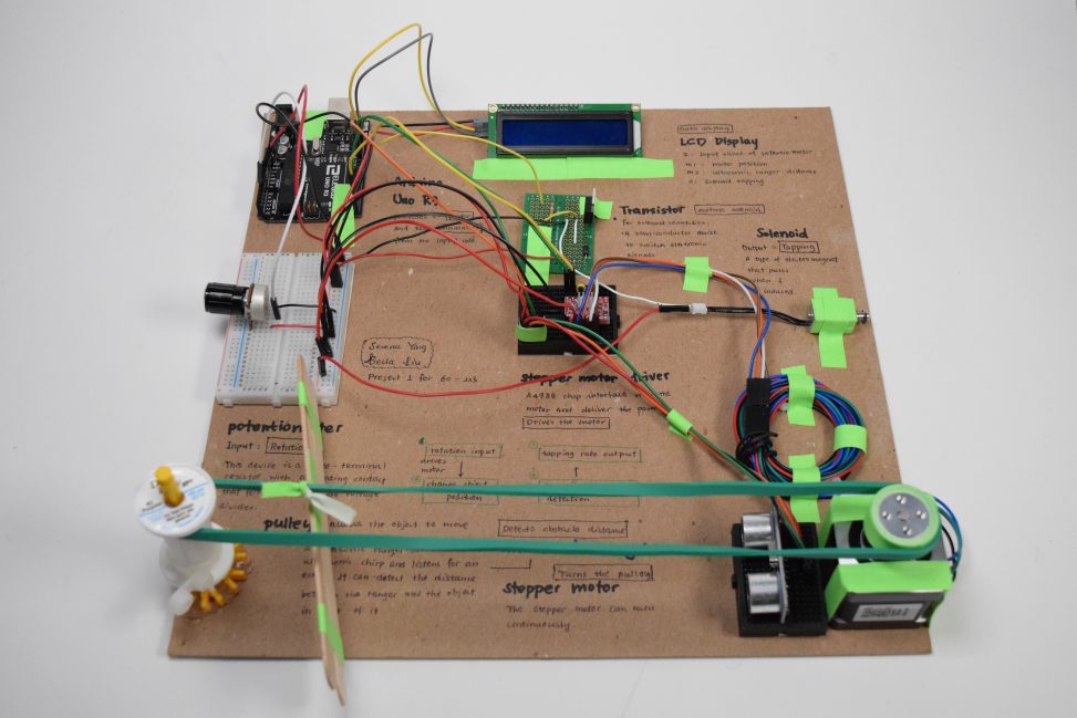
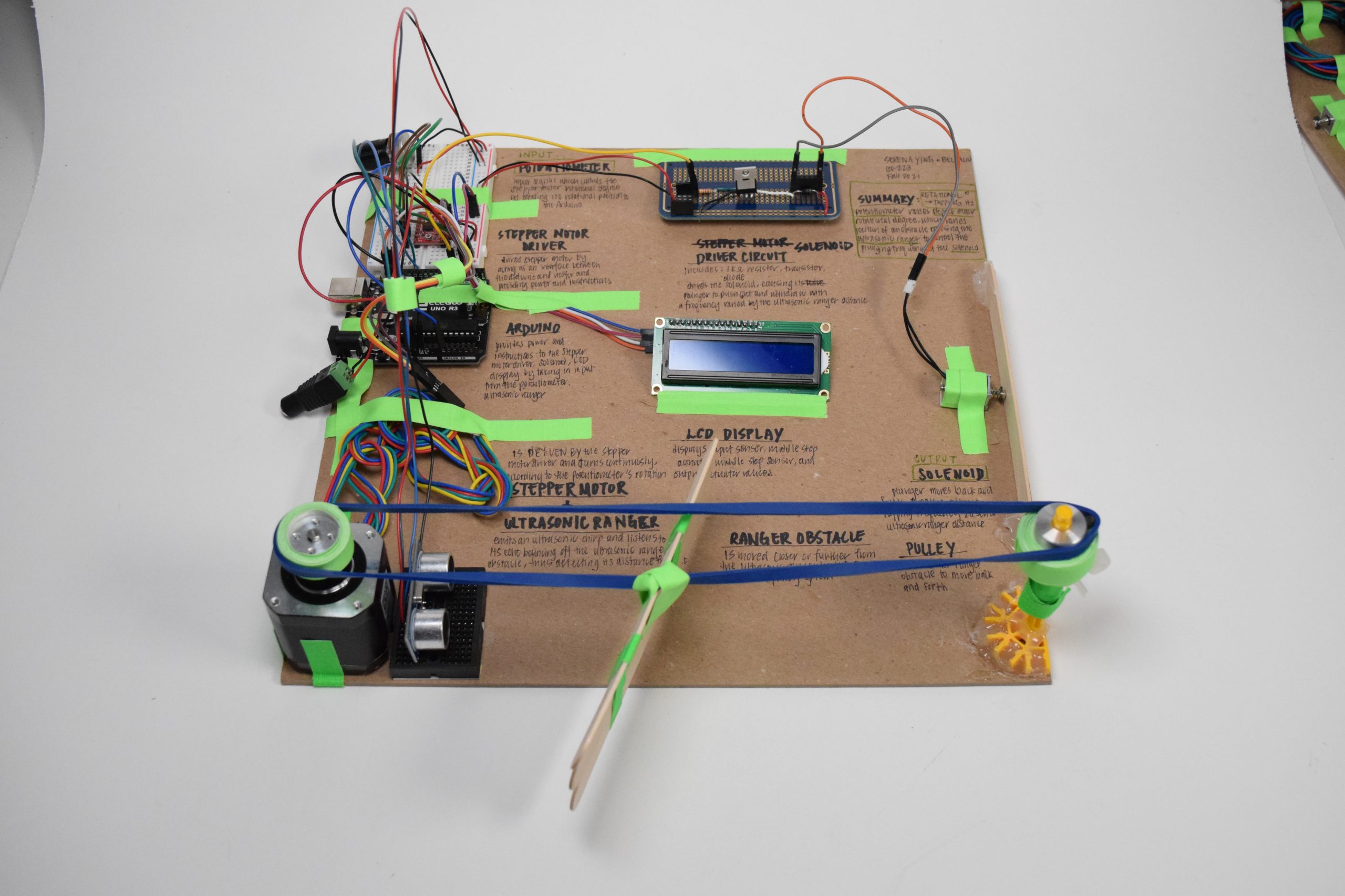
This project is a double transducer that takes a rotational position (0-90) as input and produces a frequency of tapping (20-60 taps per min) as output. The double transducer takes in the rotational degree and adjusts the rotation of the stepper motor accordingly. The stepper motor then drives the pulley to change the position of the obstacle. The ultrasonic ranger detects the distance between the obstacle and itself to adjust the frequency of tapping in accordance.
Overall Logic:
Rotational Position (Potentiometer) –> Stepper Motor Rotation –> Pulley System Movement –> Obstacle Movement –> Distance Detection by Ultrasonic Ranger –> Frequency of Tapping (Solenoid)
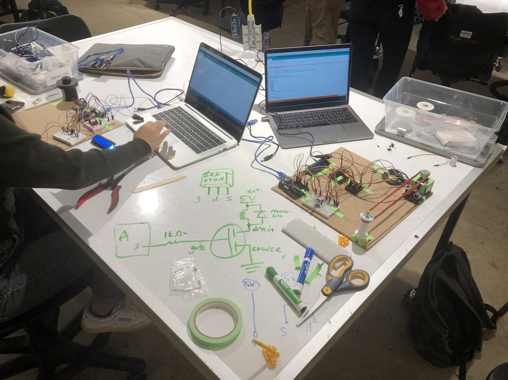
Overall Photos
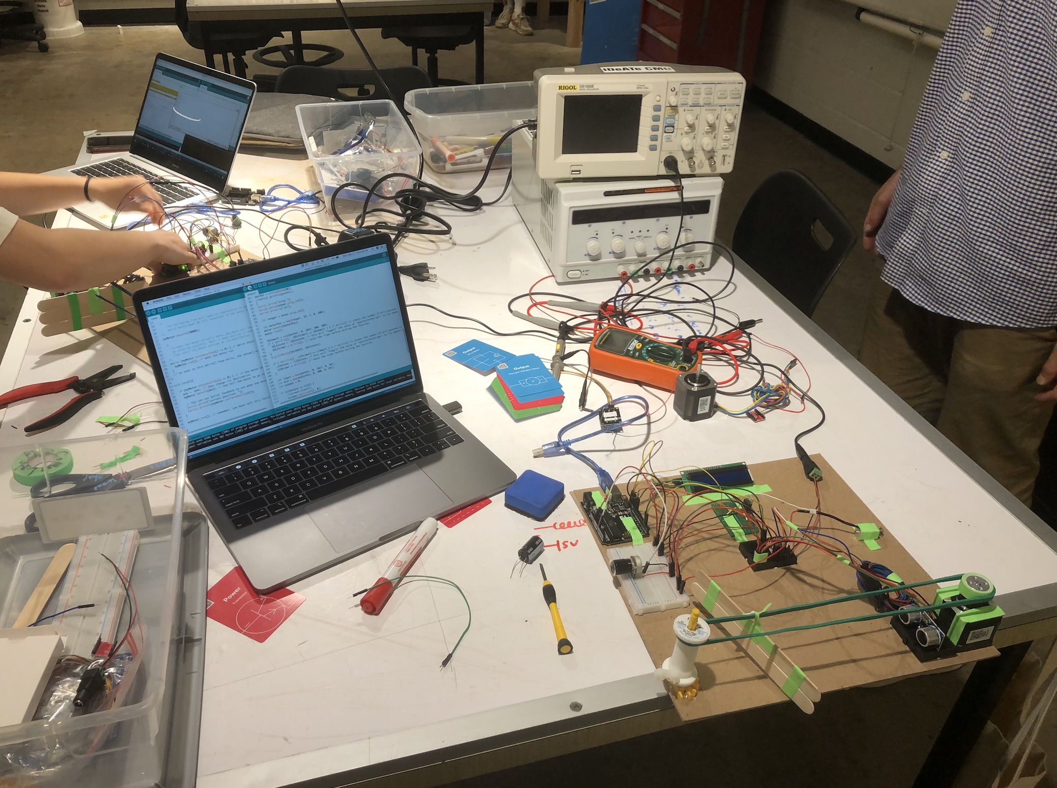
Serena’s Overall

Bella’s Overall
Detailed Photos
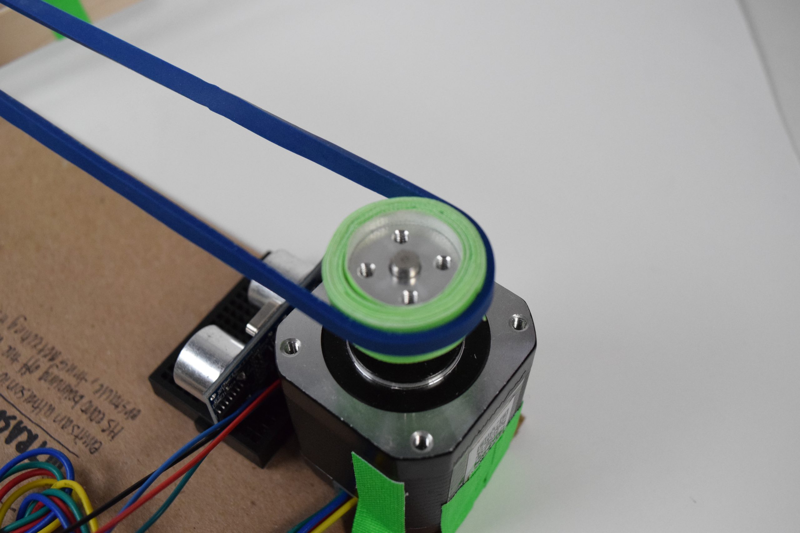
Stepper Motor
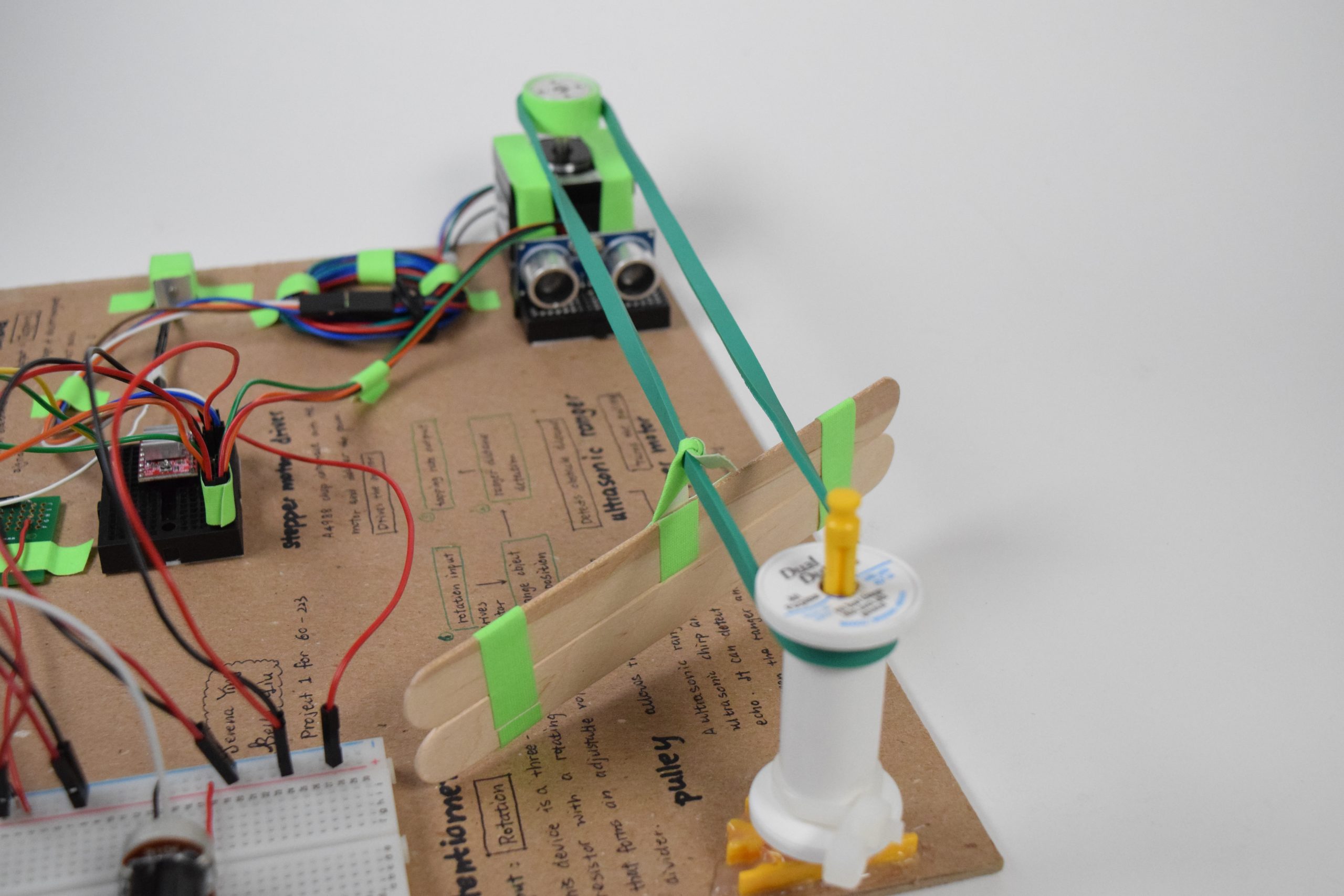
Stepper Motor Pulley System
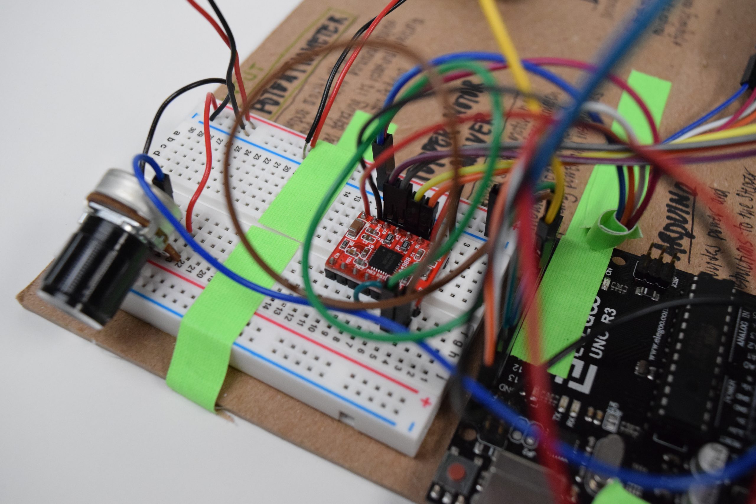
Stepper Motor Driver Closeup
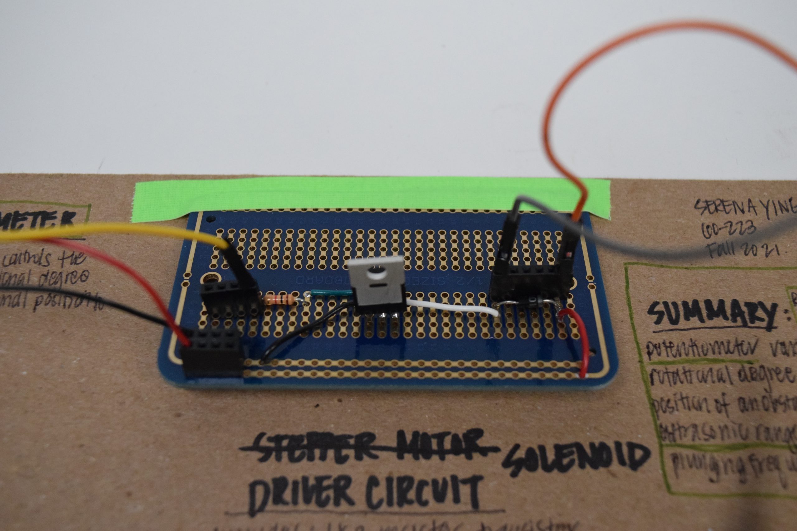
Solenoid Driver Circuit
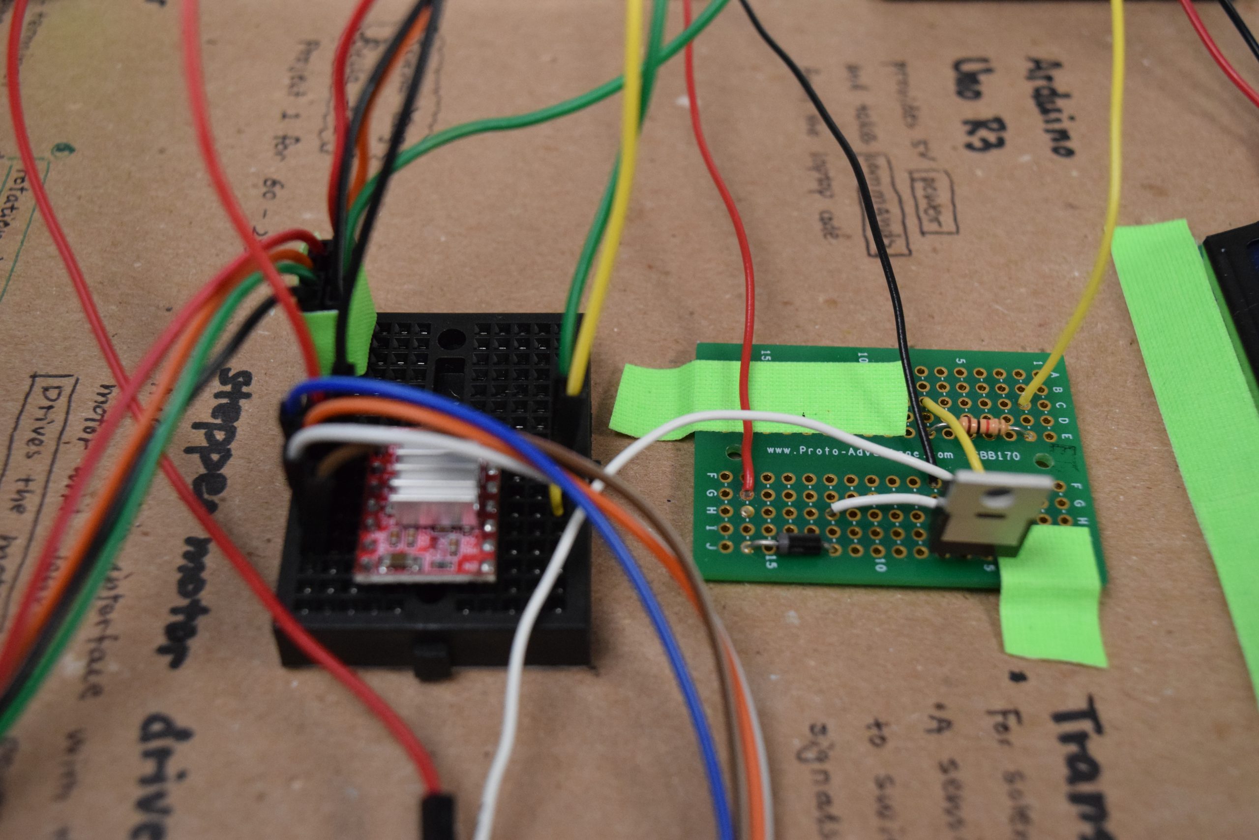
Stepper Motor (left) and Solenoid (right) Driver Circuits
Movies
Serena’s video:
Bella’s video:
Progress Images
Figuring out the solenoid voltage problem
Figuring out how to use a solenoid
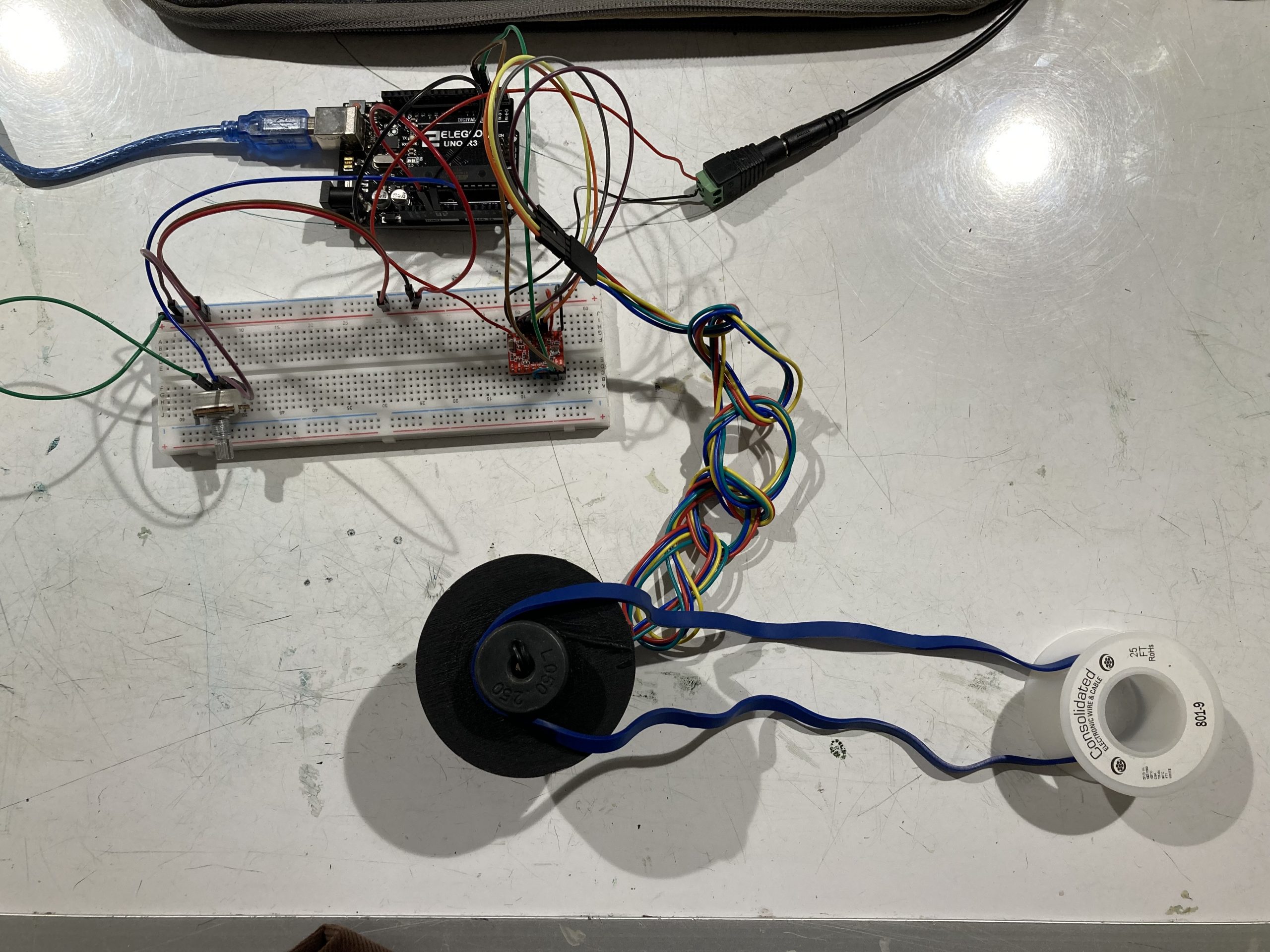
Initial prototype for pulley system with stepper motor and potentiometer
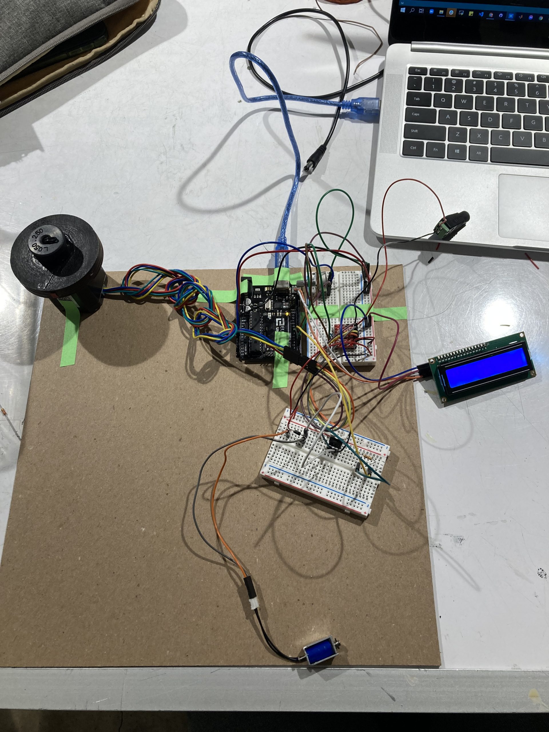
Added LCD display and solenoid to the mix after switching to a stepper motor for a more hefty rotational force
Discussion
The project taught us that implementing a fun idea could present so many challenges, ones that we anticipate and ones that come out of nowhere. For this project, some parts we were prepared to tackle with patience from the beginning, such as the pulley system controlled by the stepper motor. We spent a long time brainstorming on how to use a stepper motor, how to make the pulley work, how to move the obstacle attached to the pulley, etc. But the real frustration came from the parts that we thought would be as easy as a breeze, such as a solenoid. The solenoid seemed to be simpler than most of the things we’ve seen in class. However, it was unexpected that adding the solenoid would cause a disruption for the voltage for the entire project. The solenoid causes the 5V to drop to around 3V whenever it is activated, causing the LCD display to dim and the stepper motor to shake. After an hour of tinkering in the OH on the night before the due, we still could not find the problem. Since we left the solenoid to be the last to do, it was too late to find an alternative to solve the issue. This experience shows that every part of the project should be tested out in the beginning stage, even the ones that appear to be easy to implement.
This project also showed the importance and efficiency of the “divide and conquer” strategy. During the early stages, we experimented with different sections of the project. While one of us attempts to figure out how to use a stepper motor, the other one would fiddle with the LCD display. Being responsible for different tasks and piecing them together in the end allowed us to work efficiently and effectively within a limited time.
Functional Block Diagram

Schematic Diagram

Code
/*
 * Double Transducer: Rotational Position -> Frequency of Tapping
 *
 * Team Members: Bella Liu, Serena Ying
 *
 * Description:
 *   The program is designed to receive input from the potentiometer and convert
 *   the value to appropriate rotatoin for the stepper motor in order to control
 *   the pulley and therefore move the obstacle. The ultrasonic ranger then detects
 *   the distance between itself and the obstacle, and converts it to a frequency for
 *   the solenoid tapping accordingly.
 *
 * Pin Mapping Table:
 *
 *   Arduino pin | description
 *   ------------|-------------
 *   A0            Potentiometer
 *
 *   11            Echo pin, ultrasonic ranger
 *   12            Trigger pin, ultrasonic ranger
 *
 *    2            Step pin, A4988 driver chip for stepper motor
 *    3            Direction pin, A4988 driver chip for stepper motor
 *
 *   SDA           SDA pin, LCD display
 *   SCL           SCL pin, LCD display
 *
 *
 * References:
 *  https://courses.ideate.cmu.edu/60-223/f2021/tutorials/ultrasonic-ranger
 *  https://courses.ideate.cmu.edu/60-223/f2021/tutorials/stepper
 *  https://courses.ideate.cmu.edu/60-223/f2021/tutorials/I2C-lcd
 */

// Libraries
#include <Wire.h>
#include <LiquidCrystal_I2C.h>
#include <AccelStepper.h>
#include <NewPing.h>

//Pin for potentiometer
const int POTEN = A0;

//Pins for ultrasonic ranger
const int TRIGGER_PIN = 12;
const int ECHO_PIN = 11;
const int MAX_DISTANCE = 200;

//Pins for A4988 diver chip
const int STEP_PIN = 2; // A4988 "STEP" pin wired to Arduino pin 2 (you can change this)
const int DIR_PIN = 3; // A4988 "DIRECTION" pin wired to Arduino pin 3 (you can change this)

//Variables for LCD display
unsigned long LCDtimer = 0;
const int LCDwait = 500;
bool LCDstate = LOW;

//Pin and variables for solenoid
const int SOLENOID = 5;//This is the output pin on the Arduino
unsigned long SOLEtimer = 0;
int SOLEwait = 0;
bool SOLEstate = LOW;

//Setups
NewPing sonar(TRIGGER_PIN, ECHO_PIN, MAX_DISTANCE);
LiquidCrystal_I2C screen(0x27, 16, 2);
AccelStepper motor(1, STEP_PIN, DIR_PIN);

void setup() {

  //Pin setup
  pinMode(POTEN, INPUT);
  pinMode(SOLENOID, OUTPUT);

  Serial.begin(9600);
  Serial.begin(115200);

  //LCD screen initialization
  screen.init();
  screen.backlight();

  // set cursor to home position, i.e. the upper left corner
  screen.home();

  //Stepper motor initialization
  motor.setMaxSpeed(6000); // measured in steps per second
  motor.setAcceleration(8000); // measured in steps per second squared

}

void loop() {

  //Variables to store values for potentiometer and ultrasonic ranger
  int potVal = analogRead(A0);
  int ranger = sonar.ping_cm();

  //Printing potentiometer and ultrasonic ranger values in the monitor for debugging
  Serial.println(potVal);
  Serial.print("ping:");
  Serial.print(sonar.ping_cm());
  Serial.println("cm");

  //Adjust the stepper motor rotation according to the rotational degree
  int motorPos = map(potVal, 0, 1023, 0, 400);
  motor.moveTo(motorPos);
  motor.run();

  //Adjust the frequency of tapping based on the distance detected by the ranger
  SOLEwait = map(ranger, 19, 0, 800, 300);
  if ( (millis() - SOLEtimer) >= SOLEwait ) {
    SOLEstate = !SOLEstate;
    SOLEtimer = millis();
  }
  digitalWrite(SOLENOID, SOLEstate);

  //display on the LCD
  if ( (millis() - LCDtimer) >= LCDwait ) { // millis() is always the number of milliseconds since the Arduino powered up
    LCDstate = !LCDstate; // this will "toggle" the value of "quarterStateLight" to its opposite
    LCDtimer = millis(); // reset the timer before exiting the function.
  }

  //display values for the LCD
  int input = map(potVal, 0, 1023, 0, 99);
  int mid = map(motorPos, 0, 400, 0, 99);
  int mid2 = map(ranger, 20, 0, 0, 99);
  int output = map(SOLEwait, 300, 100, 0, 99);

  if (LCDstate == HIGH) {
      screen.clear();
      screen.print("i:");
      screen.setCursor(6,0);
      screen.print("m:");
      screen.setCursor(6,1);
      screen.print("m:");
      screen.setCursor(12,1);
      screen.print("o:");
      screen.setCursor(2, 0);
      screen.print(input);
      screen.setCursor(8, 0);
      screen.print(mid);
      screen.setCursor(8, 1);
      screen.print(mid);
      screen.setCursor(14,1);
      screen.print(output);
  }

}