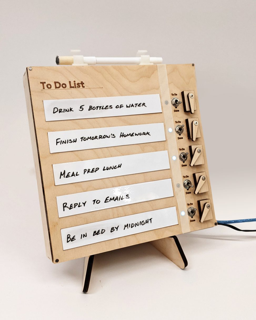
A reusable to do list that resets itself every morning to help you keep track of your daily tasks.
Photos

Final to do list – overall photo
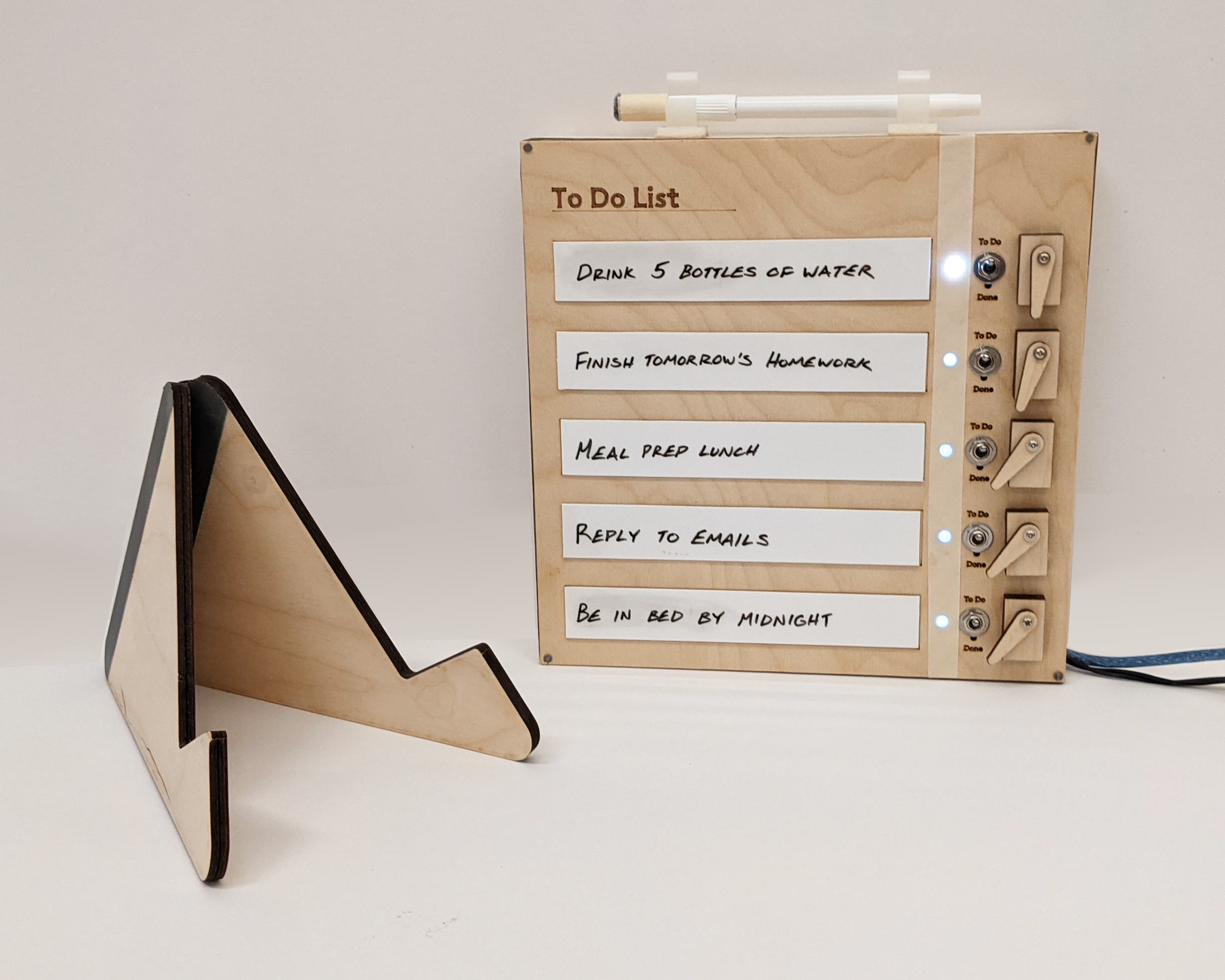
Detail view of the separate components: the list, the stand, and the marker holder
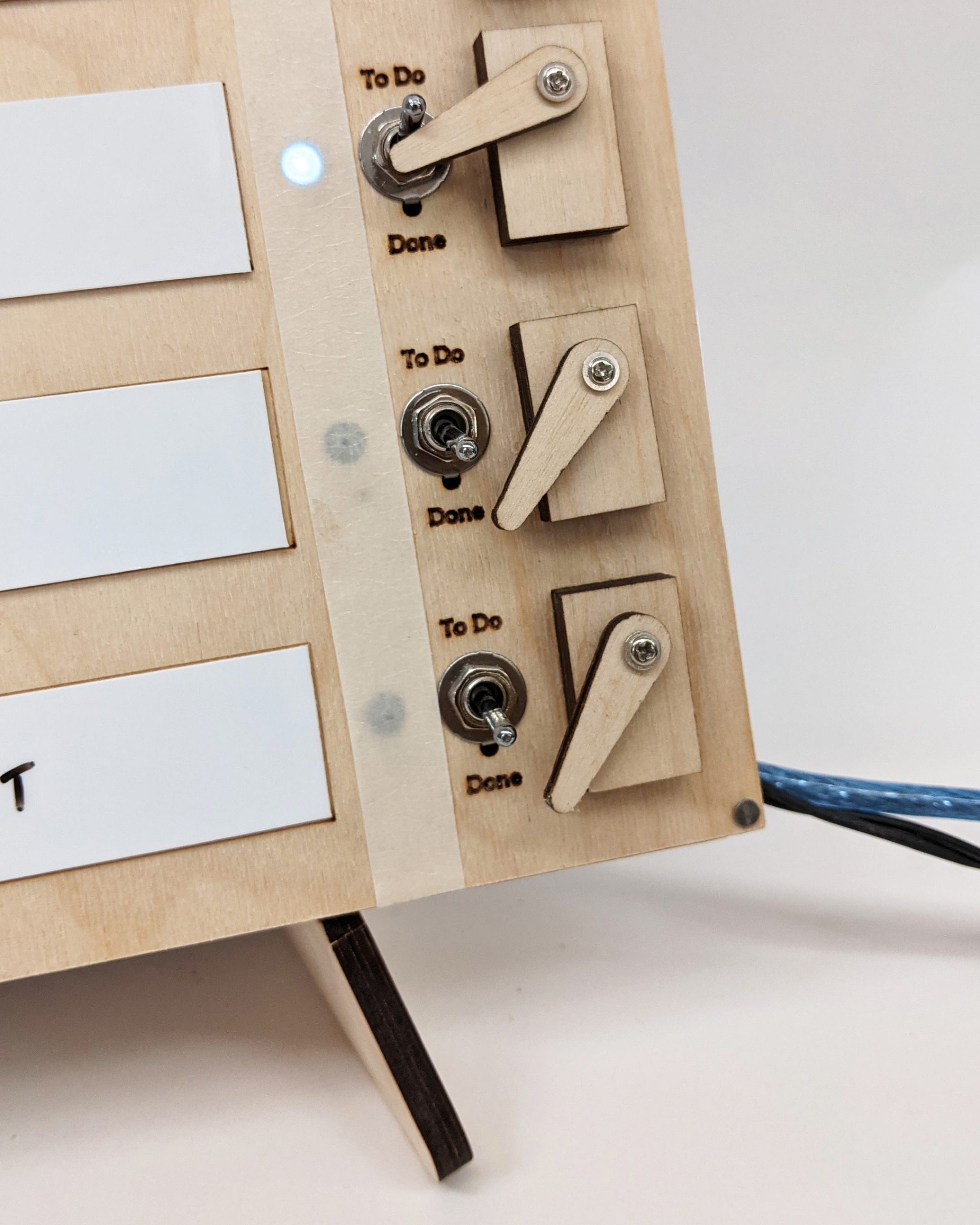
Detailed view of the servo arms activating the switches and turning the LEDs back on
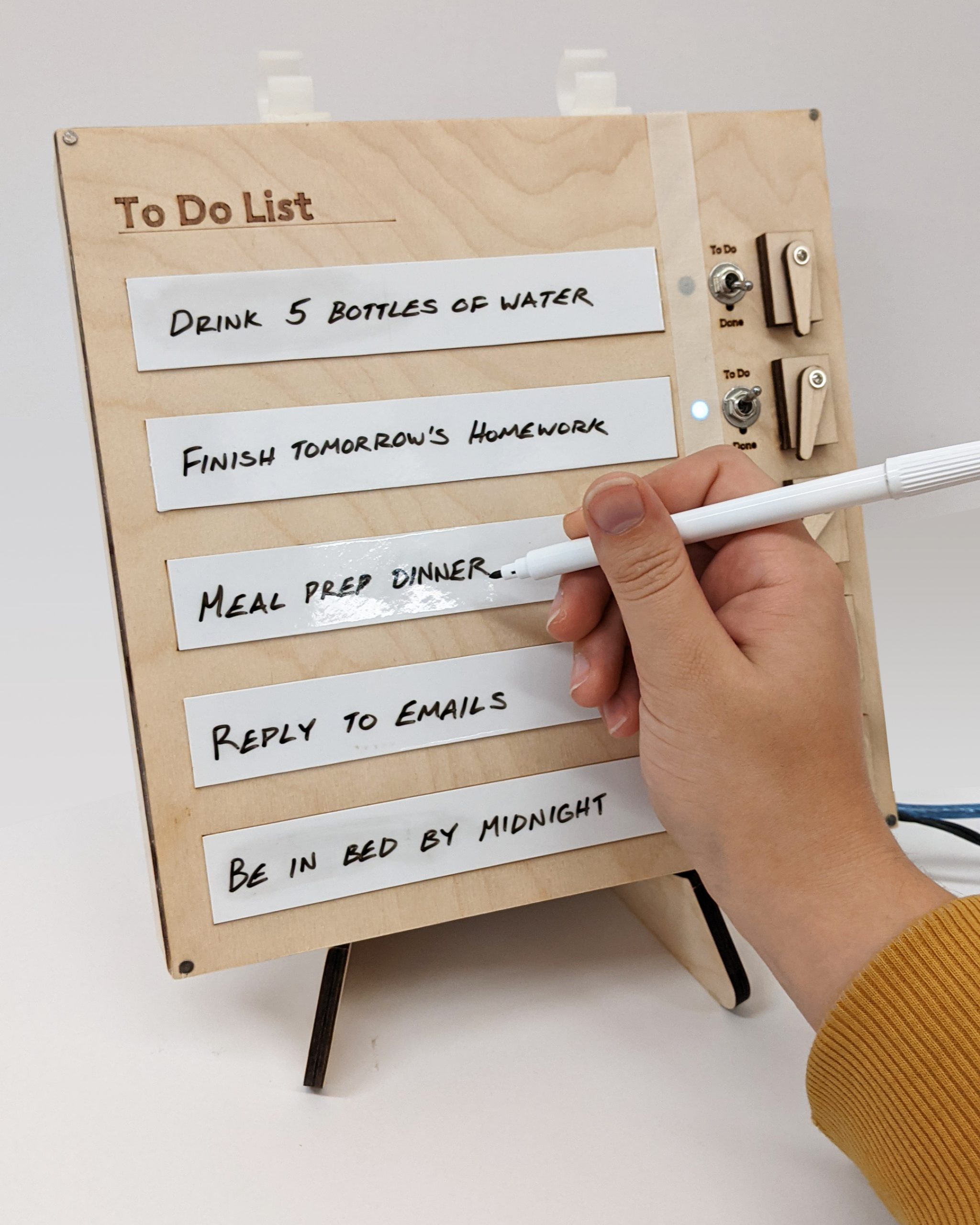
Demonstration of the whiteboard areas for easy editing and changing of daily tasks
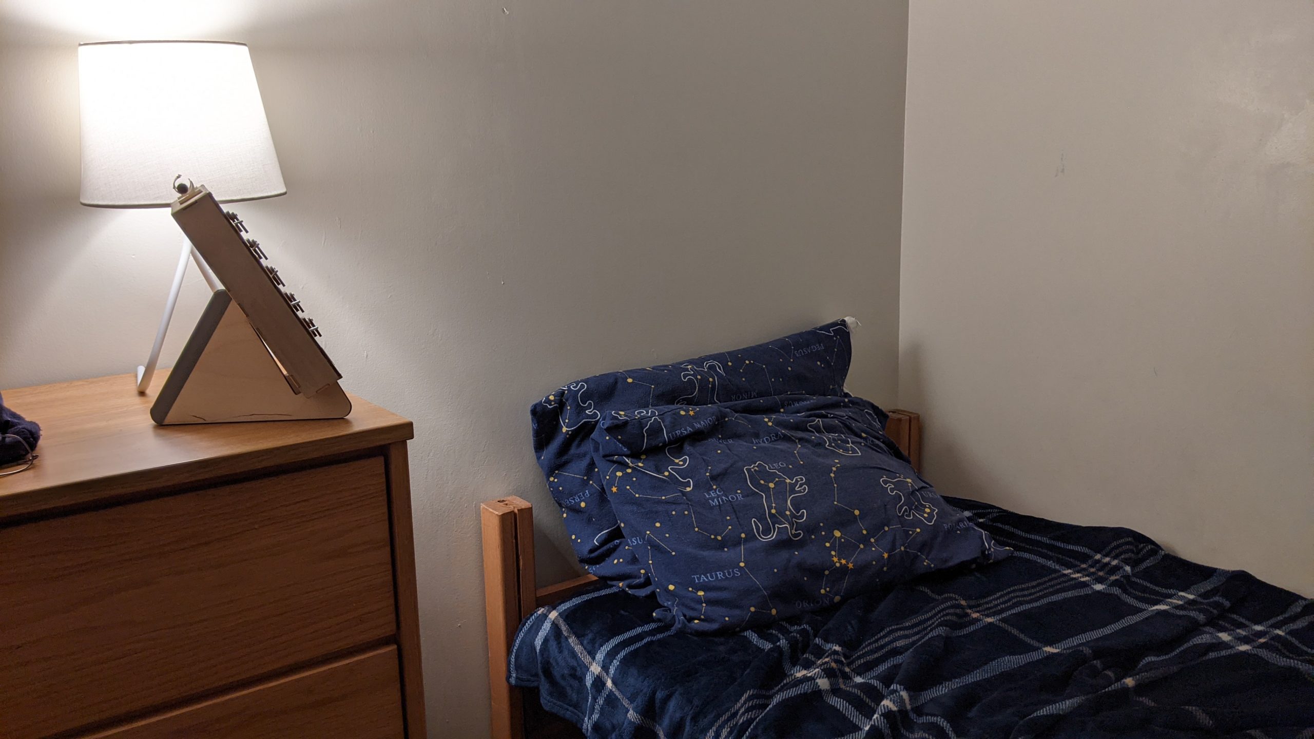
View of the list in context, being placed by the bed for reminders in the morning and review at night
Process: Decision Points
One of the biggest decision points for me along this process was figuring out how I would reset the tasks each day. I had decided to use these manual switches in my design since I felt that turning them on and off reflected the same satisfaction of crossing something off a list, but this made it more difficult to reset the tasks compared to a button, as well as the challenge to scale up my design to accommodate five tasks. I contemplated several different methods such as a panel that could shift up and down to turn the switches back on, changing which side was “To Do” and which was “Done” each day, or finding a way to flip the switches internally, but these all had quite adverse effects on the human interaction with these switches, often compromising the ability to flip the switches manually. In my prototype and later my final design, I decided to use a servo arm to flip the switches manually since they worked consistently and did not interfere with the human interaction when not in use. While this was mechanically heavy and required many servos when applied to five tasks, I felt that this was the most efficient and effective method for my time.
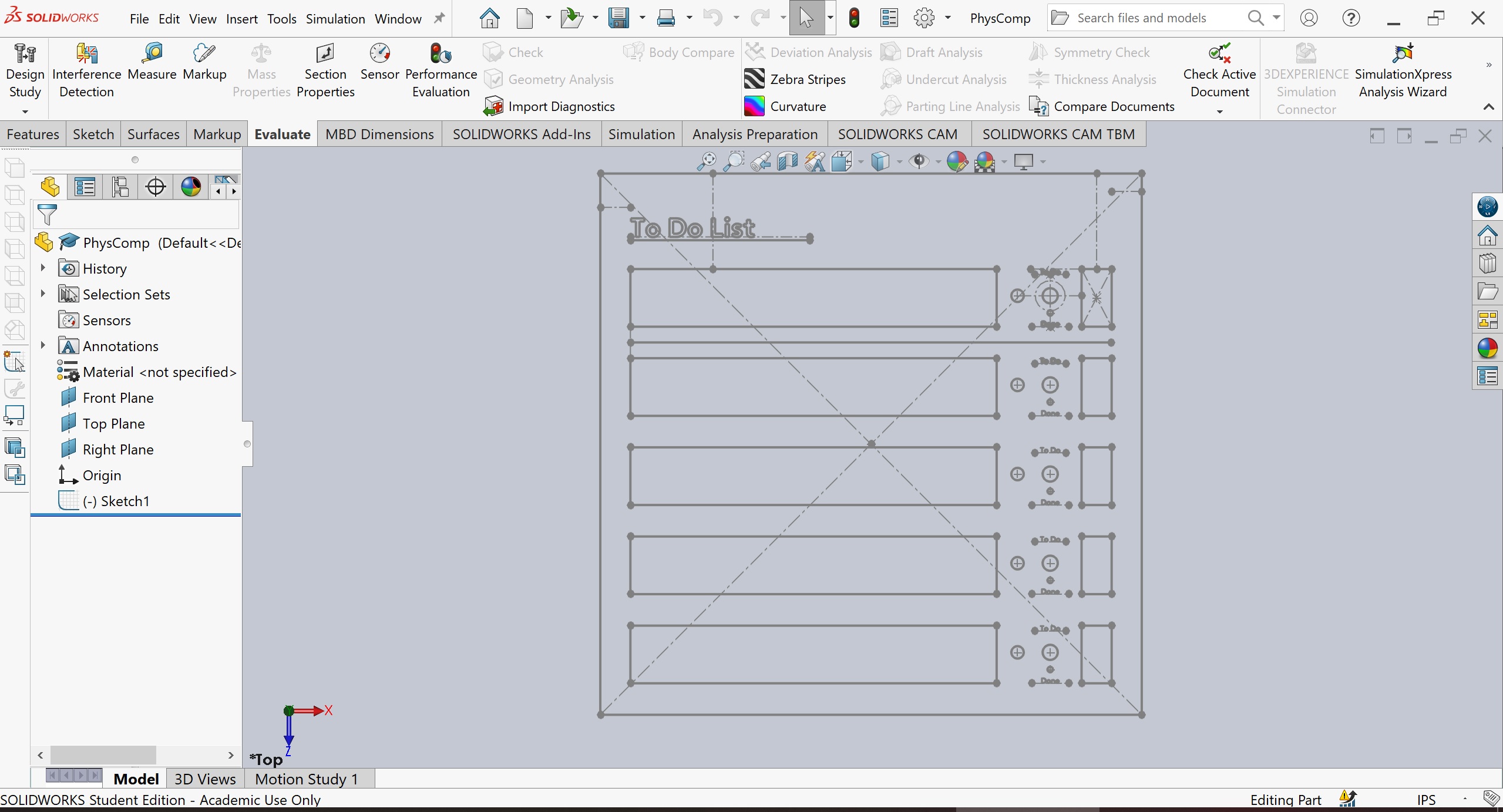
Another major decision point in this process was what the layout of the items would be on the final product. This had to be done later in the process since it was largely driven by the side of the components relative to one another, but it was also the deciding factor in much of my final wiring layout and had to take that into consideration as well. While I had initially envisioned the board being taller than it was wide, being close to 8.5 by 11 paper dimensions, the dimensions for ideal writing space as well as the mechanics made it much shorter than I expected. In the end, I opted for square proportions as it seemed to fit five tasks (my average amount of daily tasks) nicely while also providing enough housing space for the internal components.
Process Images
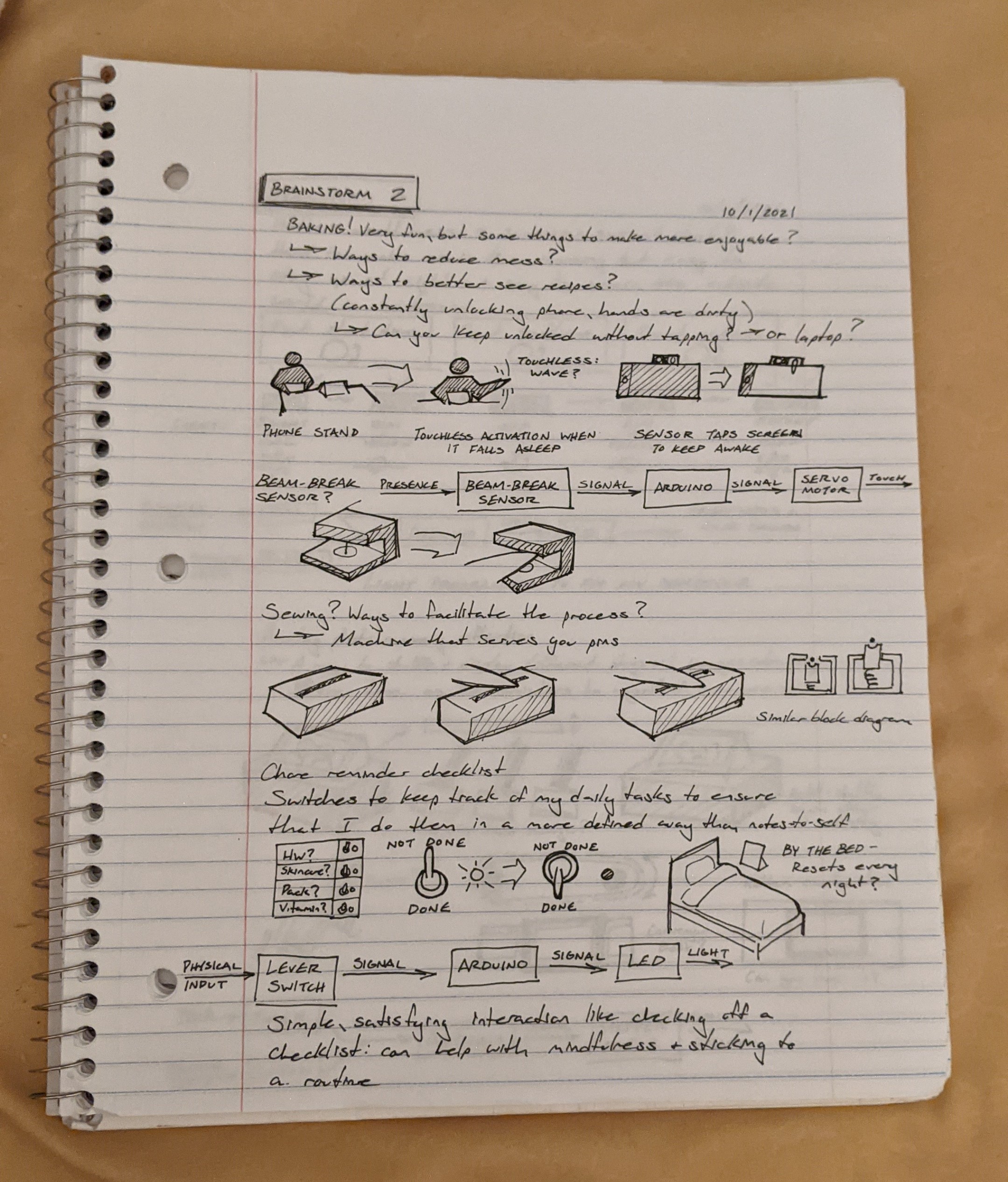
My initial concept sketch at the bottom of the page had all the right components, but it was definitely a whole other challenge to determine the logistics and actually build it.
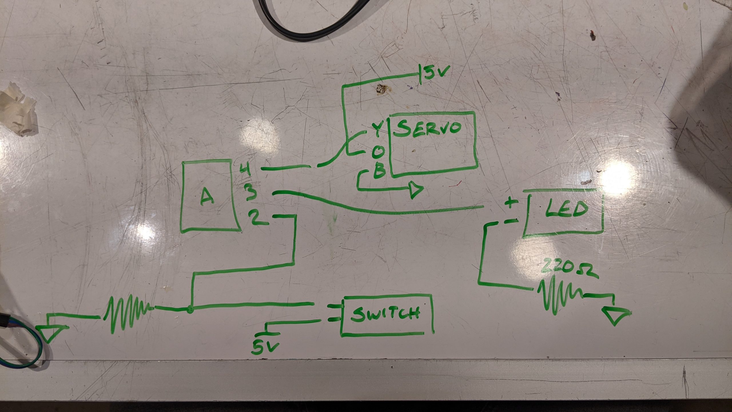
The highly simplified wiring diagram I made for myself before attempting to wire the same structure five times over.
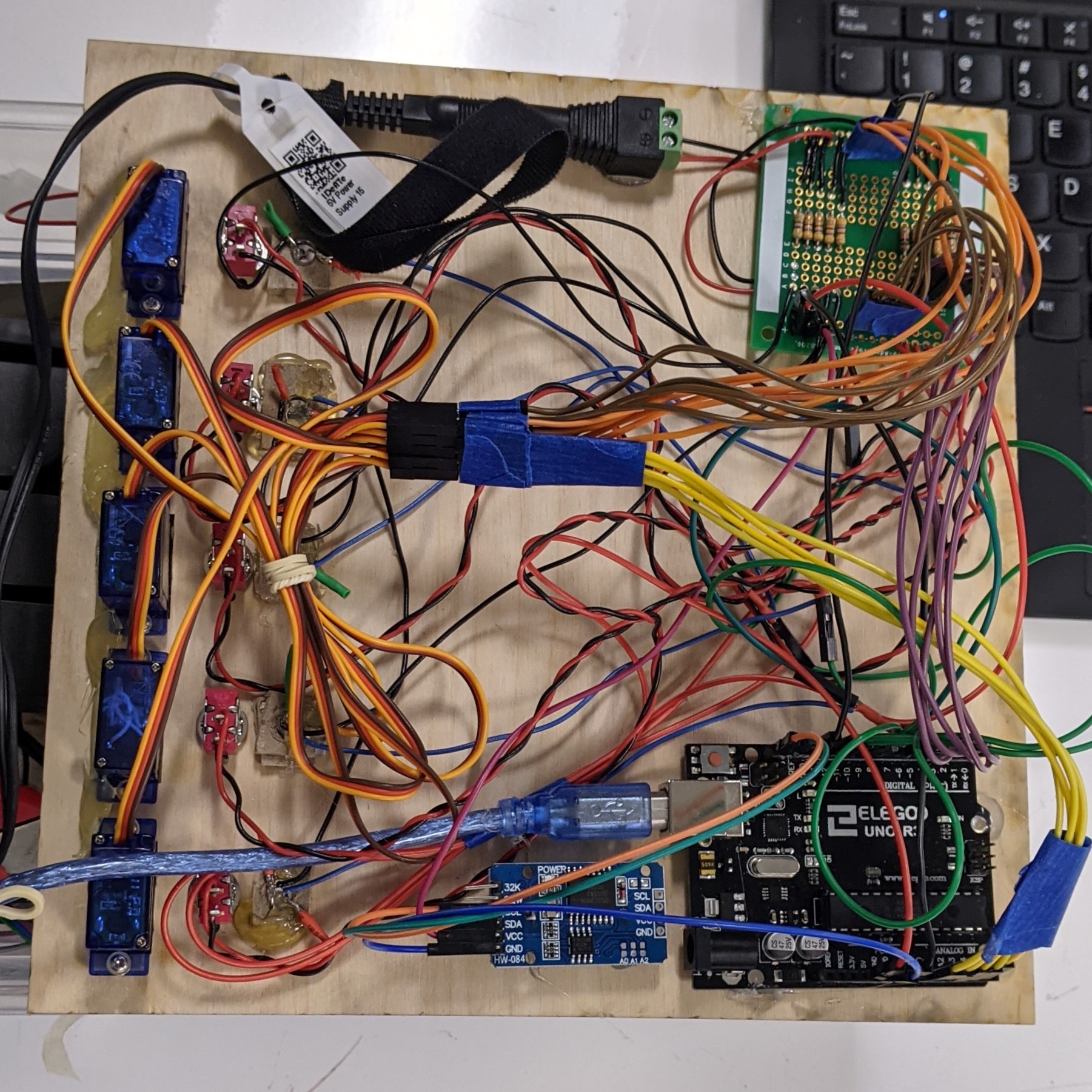
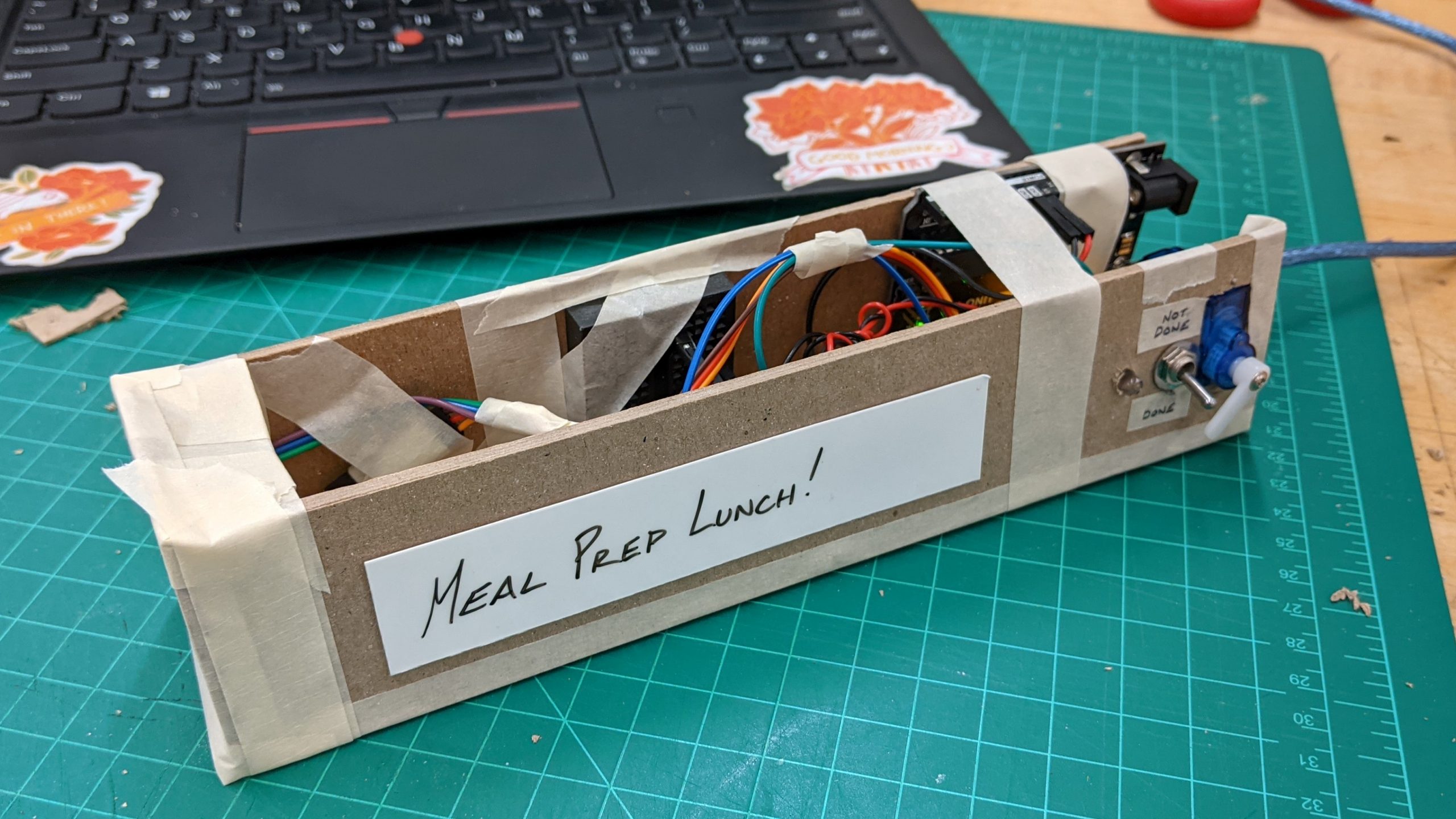
With the same wiring repeated five times, it was important that I kept the wires as organized as possible, leading me to color code them (yellow for the servo, purple for the switches, blue for the LEDs, and so on).
Despite my careful planning of the wiring and implementation, some wires inevitably changed order, leaving my inputs and outputs quite jumbled. While the LEDs, servos, and switches sections stayed together, Switch 1 would turn off LED 4 and the servos would activate all out of order, making it quite hard to sort out. I decided to make the switch wiring the “driving” control by keeping that in place and changing the mapping of the LEDs and servos to match them.
Discussion
Overall, I am quite happy with how this project turned out! Coming from very little coding experience and no experience with electronics, I think I am quite proud of what I have been able to accomplish. The main goal I had for myself with this project, in the words of one of my professors, was to have “simple things done well” and choose something that would allow me to ensure it would be functional and resolved to the best of my ability. While I had some feedback regarding “a reward / punishment route” to provide motivation for these tasks, I wanted to focus more on what made traditional to-do lists helpful and satisfying for me and what works best for my lifestyle. I didn’t want to add a punishment system because I felt that would hinder the likelihood of me using this in the future, and I enjoy the passive, no pressure nature of to-do lists as they are now with more gentle reminders of what I should get done. While the code and wiring seemed like it would be quite simple and straightforward, it was surprisingly still quite the challenge, especially when doing things five times over! One of the biggest challenges for me was getting the mechanism of the servos to actually flip the switches, as I had spent many hours troubleshooting having them hit and go too far, being at the wrong height to hit and have enough force, having servos that did not work or were too weak, and so on. The main takeaway from that experience for me was how many different problems can show up with the same error and to be mindful that what worked to solve the problem last time may not work again in the same way. Despite these challenges, I think I learned a lot about making something “real” as in design we often stop our process at the concept and rarely resolve the finer details to make a model that works as intended. If I were to do this project again, knowing what I know now, I would love to implement some of the feedback that I got from my peers, such as “being to control each section”, as I think that would make the product much more refined by only switching on the ones that had been turned off.
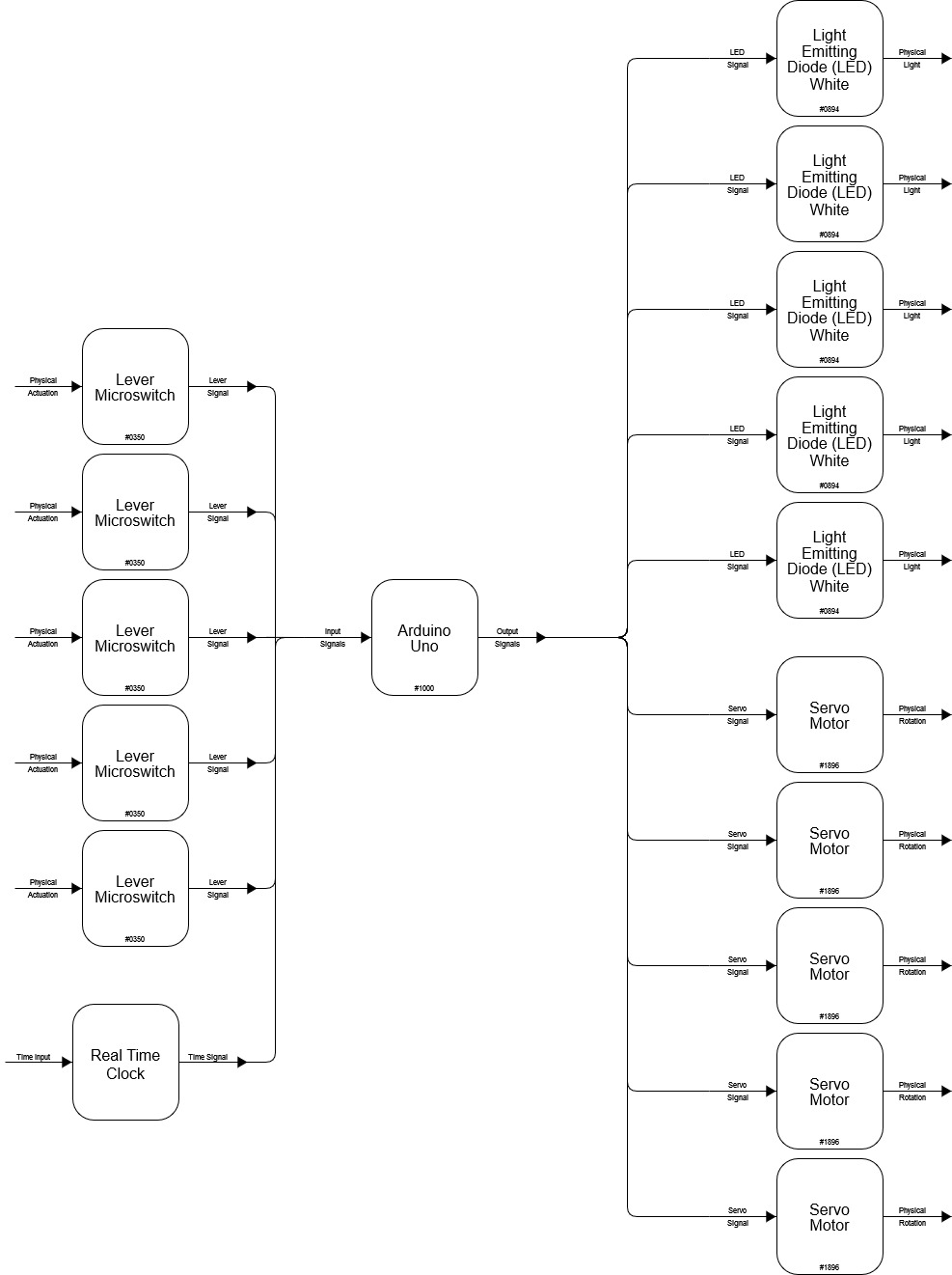
Block Diagram
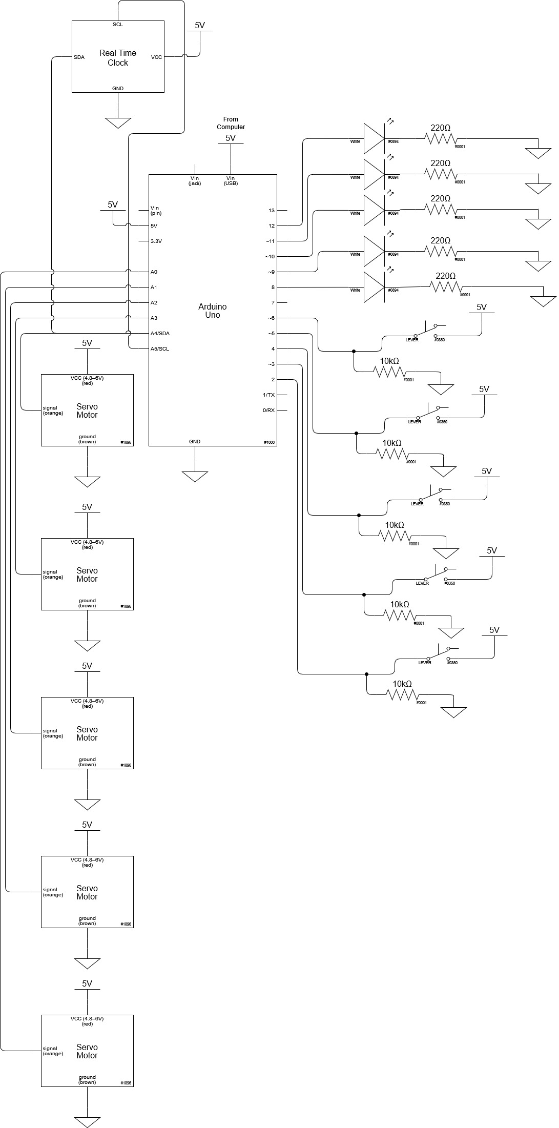
Schematic Diagram
Code
/*
Reusable To Do List
Description: This project creates a 5 switch task system with LEDs to signal whether or not they are
flipped and the task is done, additionally with a real-time-clock plugin for servo motors to
reset the switches and tasks at aspecified time each day.
Resources Used:
Real Time Clock: https://create.arduino.cc/projecthub/MisterBotBreak/how-to-use-a-real-time-clock-module-ds3231-bc90fe
Mechanism Inspiration: https://create.arduino.cc/projecthub/viorelracoviteanu/useless-box-with-arduino-d67b47
*/
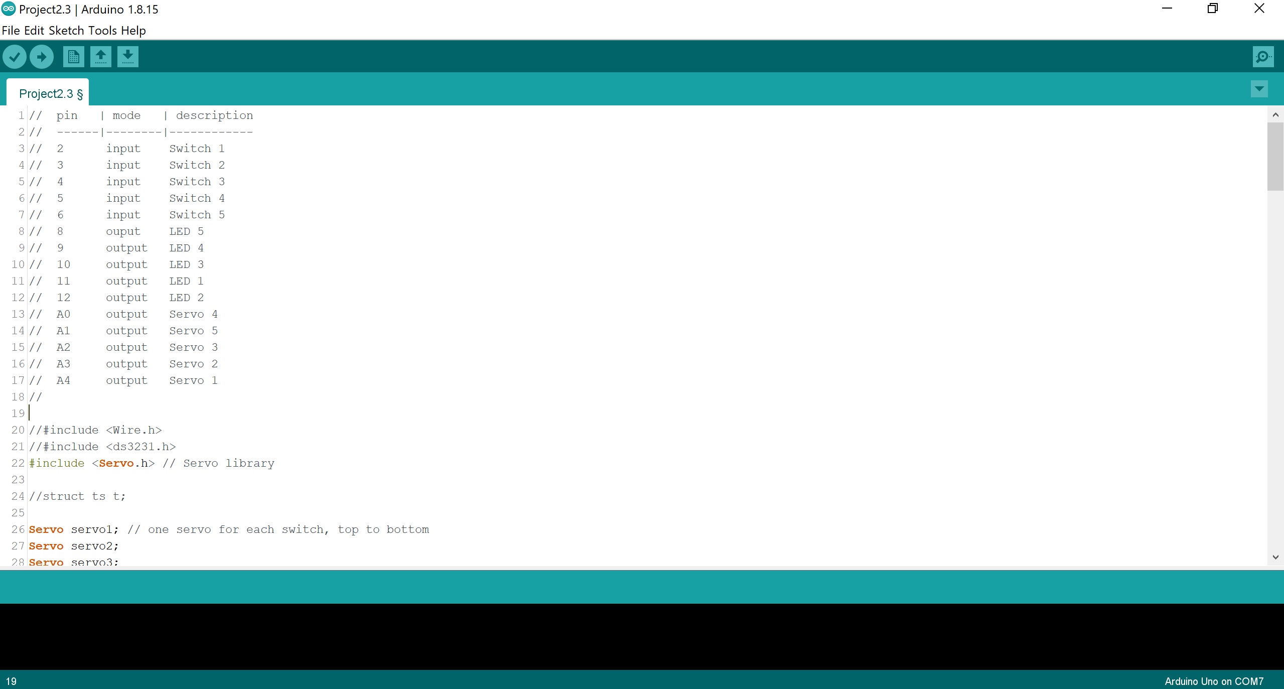
// PIN MAPPING
// pin | mode | description
// ------|--------|------------
// 2 input Switch 1
// 3 input Switch 2
// 4 input Switch 3
// 5 input Switch 4
// 6 input Switch 5
// 8 ouput LED 5
// 9 output LED 4
// 10 output LED 3
// 11 output LED 1
// 12 output LED 2
// A0 output Servo 4
// A1 output Servo 5
// A2 output Servo 3
// A3 output Servo 2
// A4 output Servo 1
//
//#include <Wire.h>
//#include <ds3231.h>
#include <Servo.h> // Servo library
//struct ts t;
Servo servo1; // one servo for each switch, top to bottom
Servo servo2;
Servo servo3;
Servo servo4;
Servo servo5;
const int SERVOPIN1 = A4; //Mappings change to fit wiring of switches
const int SERVOPIN2 = A3;
const int SERVOPIN3 = A2;
const int SERVOPIN4 = A0;
const int SERVOPIN5 = A1;
const int SWITCHPIN1 = 2;
const int SWITCHPIN2 = 3;
const int SWITCHPIN3 = 4;
const int SWITCHPIN4 = 5;
const int SWITCHPIN5 = 6;
const int LEDPIN1 = 11;
const int LEDPIN2 = 12;
const int LEDPIN3 = 10;
const int LEDPIN4 = 9;
const int LEDPIN5 = 8;
unsigned long timerOne = 0; //Timer for demo mode reset
void setup() {
Serial.begin(9600);
//Wire.begin();
//DS3231_init(DS3231_CONTROL_INTCN); //RTC setup
//t.hour=9;
//t.min=0;
//t.sec=0;
//t.mday=26;
//t.mon=10;
//t.year=2021;
//DS3231_set(t);
pinMode(SERVOPIN1, OUTPUT);
pinMode(SERVOPIN2, OUTPUT);
pinMode(SERVOPIN3, OUTPUT);
pinMode(SERVOPIN4, OUTPUT);
pinMode(SERVOPIN5, OUTPUT);
pinMode (SWITCHPIN1, INPUT);
pinMode (SWITCHPIN1, INPUT);
pinMode (SWITCHPIN1, INPUT);
pinMode (SWITCHPIN1, INPUT);
pinMode (SWITCHPIN1, INPUT);
pinMode (LEDPIN1, OUTPUT);
pinMode (LEDPIN1, OUTPUT);
pinMode (LEDPIN1, OUTPUT);
pinMode (LEDPIN1, OUTPUT);
pinMode (LEDPIN1, OUTPUT);
servo1.attach(SERVOPIN1); // set up each servo on the corresponding data pin
servo2.attach(SERVOPIN2);
servo3.attach(SERVOPIN3);
servo4.attach(SERVOPIN4);
servo5.attach(SERVOPIN5);
servo1.write(140); // servo reset to neutral position
servo2.write(140);
servo3.write(140);
servo4.write(140);
servo5.write(140);
}
void loop() {
int switch1State;
switch1State = digitalRead(SWITCHPIN1);
int switch2State;
switch2State = digitalRead(SWITCHPIN2);
int switch3State;
switch3State = digitalRead(SWITCHPIN3);
int switch4State;
switch4State = digitalRead(SWITCHPIN4);
int switch5State;
switch5State = digitalRead(SWITCHPIN5);
if (switch1State == 1) {
digitalWrite (LEDPIN1, HIGH); //Mapping switch state to LED state
}
if (switch1State == 0) {
digitalWrite (LEDPIN1, LOW);
}
if (switch2State == 1) {
digitalWrite (LEDPIN2, HIGH);
}
if (switch2State == 0) {
digitalWrite (LEDPIN2, LOW);
}
if (switch3State == 1) {
digitalWrite (LEDPIN3, HIGH);
}
if (switch3State == 0) {
digitalWrite (LEDPIN3, LOW);
}
if (switch4State == 1) {
digitalWrite (LEDPIN4, HIGH);
}
if (switch4State == 0) {
digitalWrite (LEDPIN4, LOW);
}
if (switch5State == 1) {
digitalWrite (LEDPIN5, HIGH);
}
if (switch5State == 0) {
digitalWrite (LEDPIN5, LOW);
}
if (millis() - timerOne >= 30000) { //Refresh rate of screen every 30000 milliseconds
// this is demo mode, in real mode: if (t.hour == 9 && millis - timerOne >= 3600000) { to occur once a day
servo1.write(30); // tell the servo to go to 90º
delay(200);
servo1.write(140);
delay(500);
servo2.write(30);
delay(200);
servo2.write(140);
delay(500);
servo3.write(30);
delay(200);
servo3.write(140);
delay(500);
servo4.write(30);
delay(200);
servo4.write(140);
delay(500);
servo5.write(30);
delay(200);
servo5.write(140);
delay(500);
timerOne = millis();
}
}