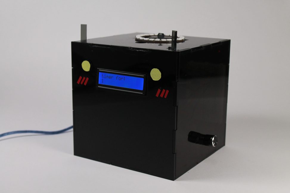
The “Mooonster Timer Box” functions as a timer for a quick sketch/timed exam session.
Images
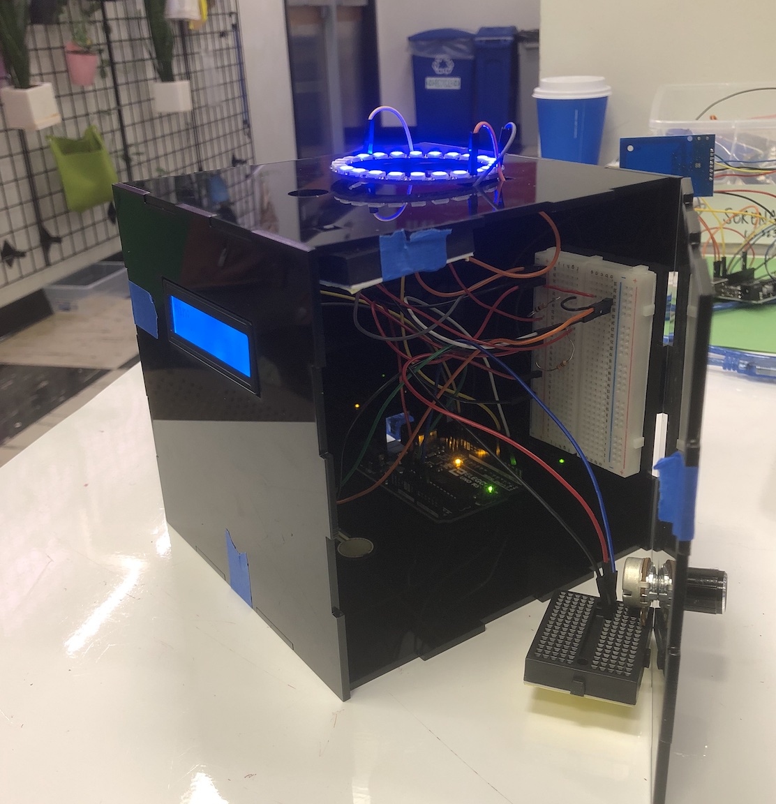
Overall Photo
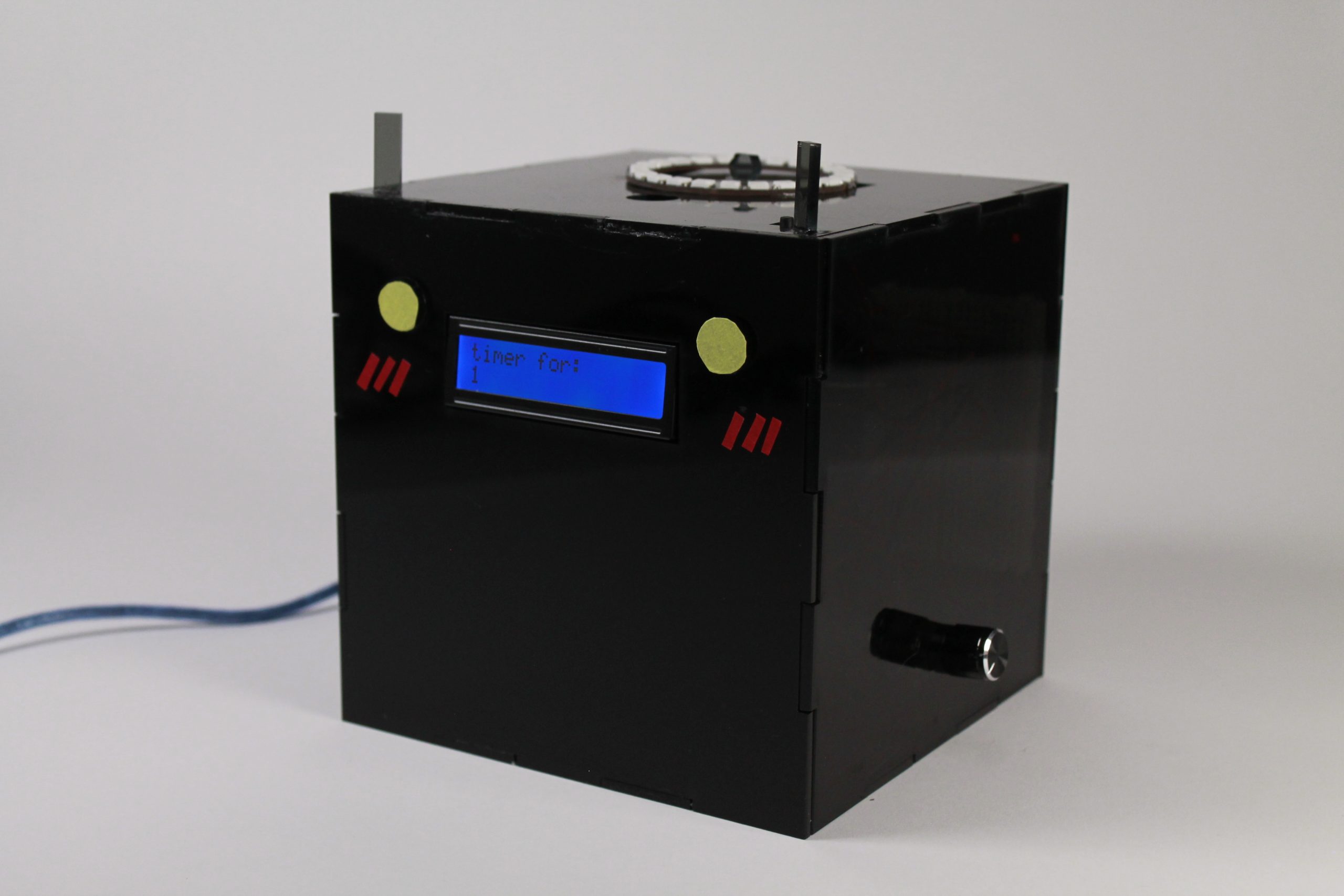
Details: Wiring Inside the Box
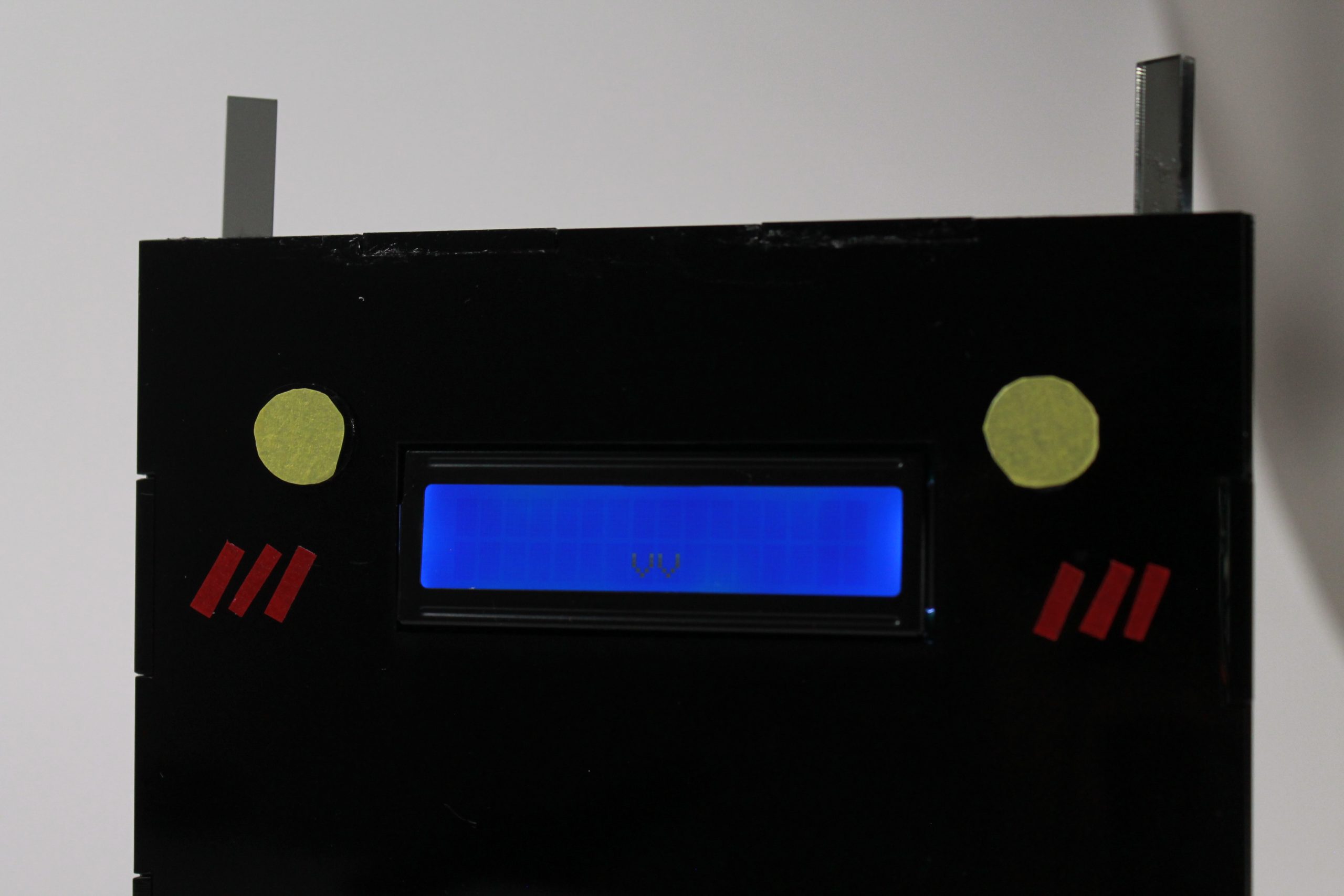
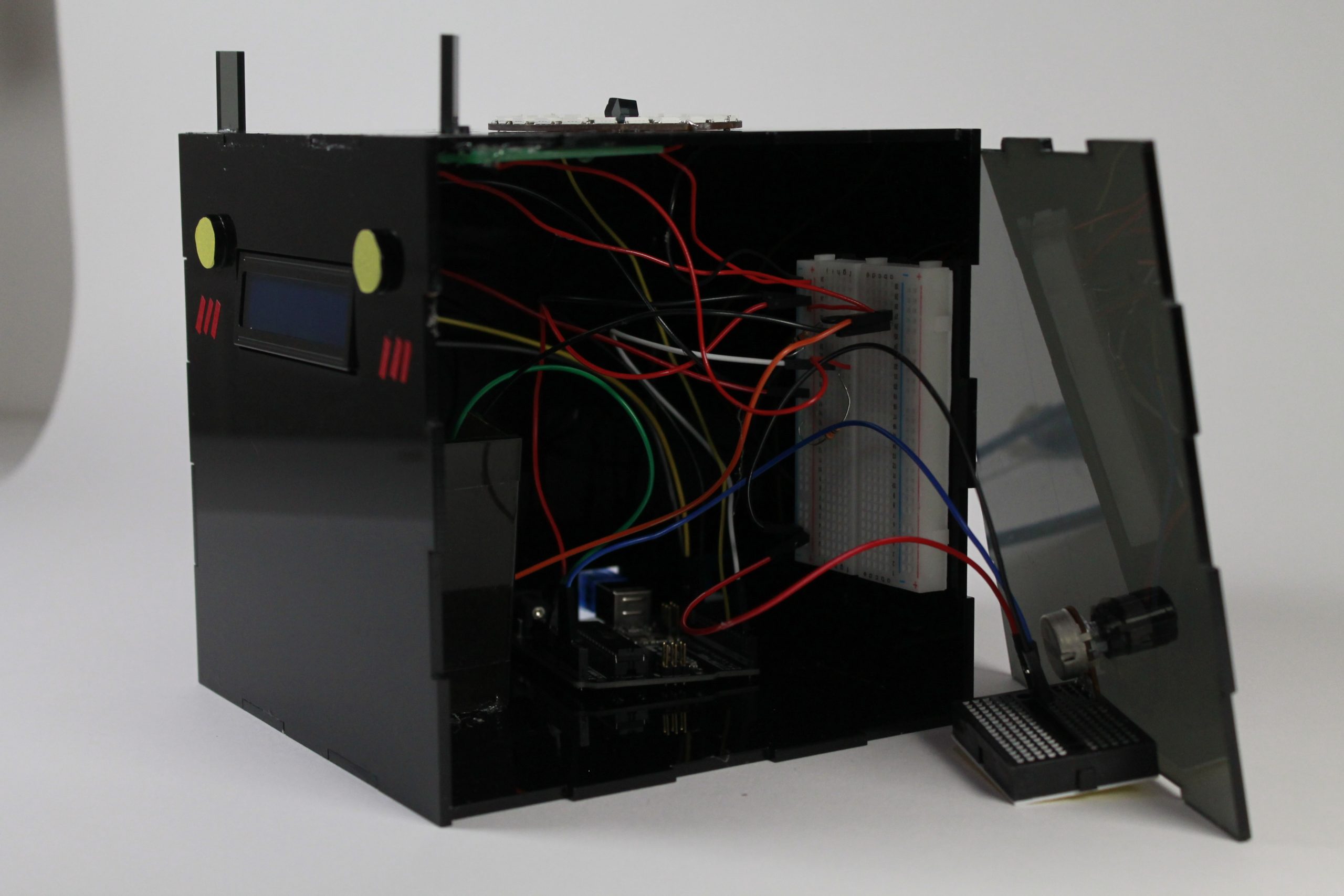
Details: The welcome kitty smile when plugged in! (·v·)
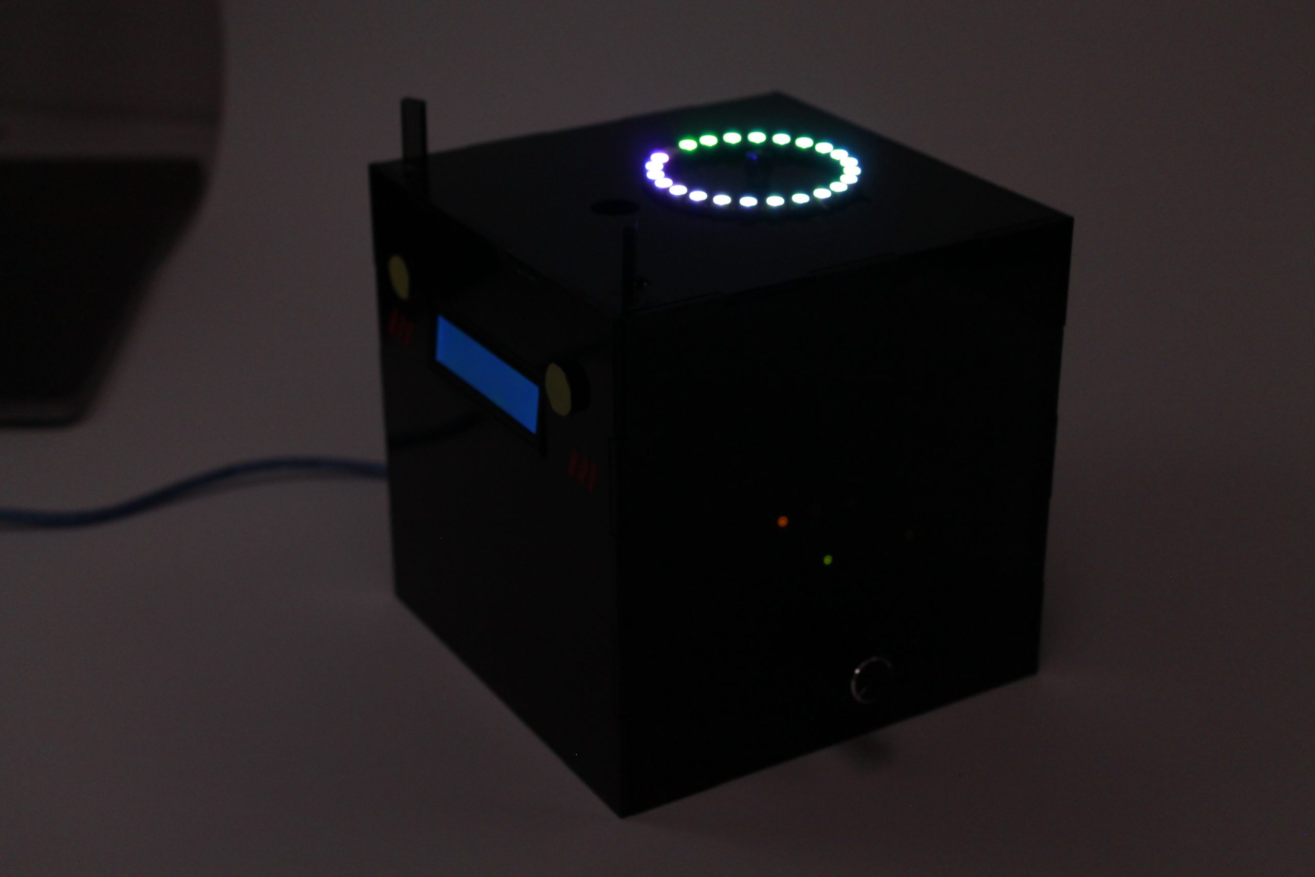
In Use: Lit up ring in the dark during countdown
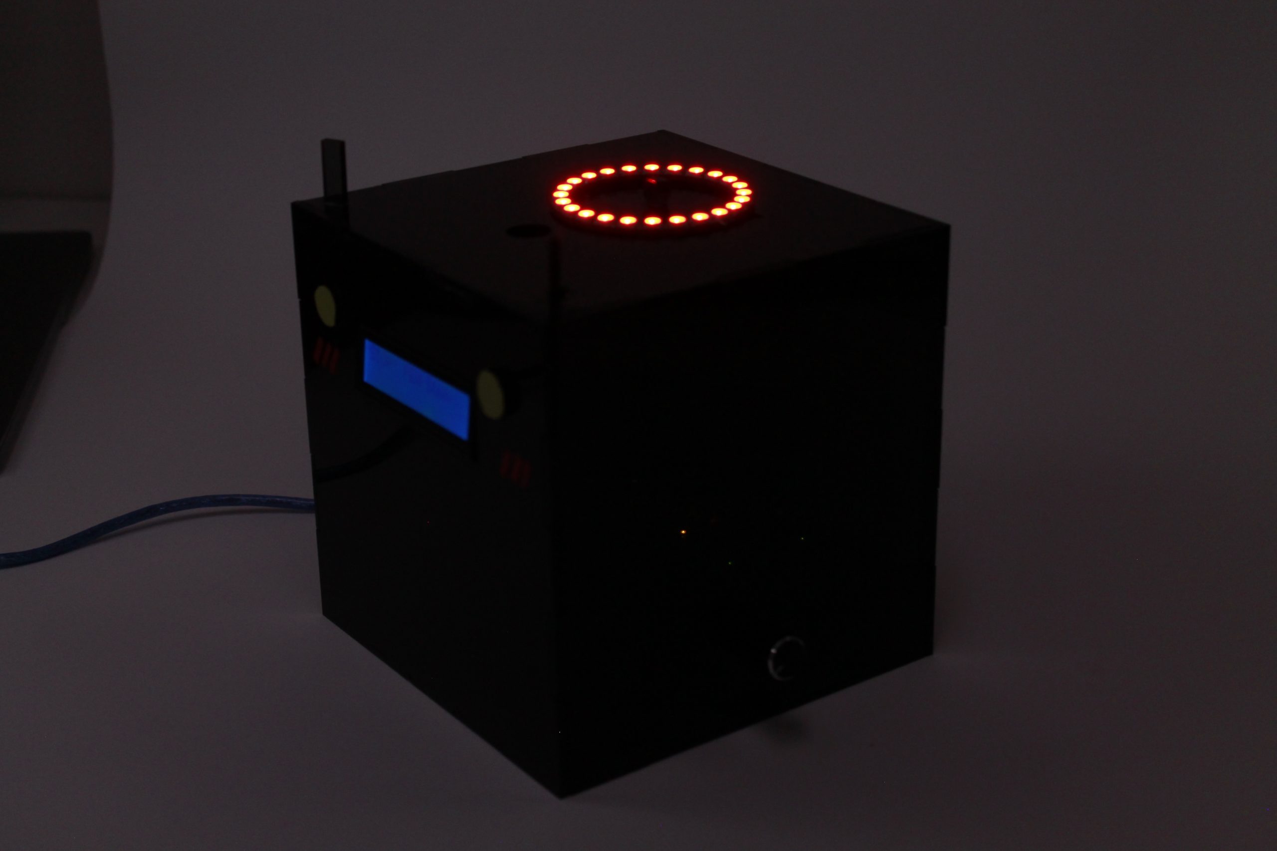
In Use: Lit up ring in the dark when the timer is up
Video Demonstration of the Usage
* Timer has been sped up for demo purposes! The timer only counted approx. 5 seconds although the timer is set to 1 minute
Process Images and Review
- Decision Point #1: Discarding the Stepper Motor and “King Arthur” Decor
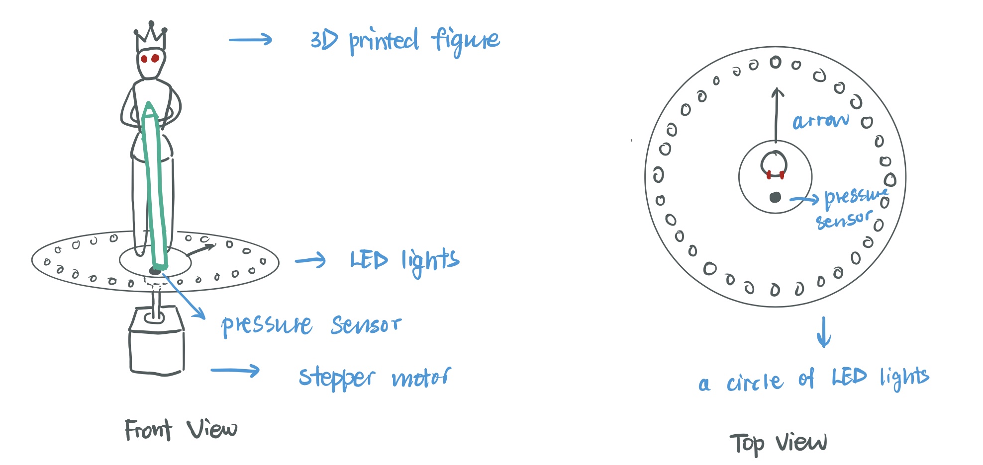
Original sketch, which features the stepper motor and King Arthur
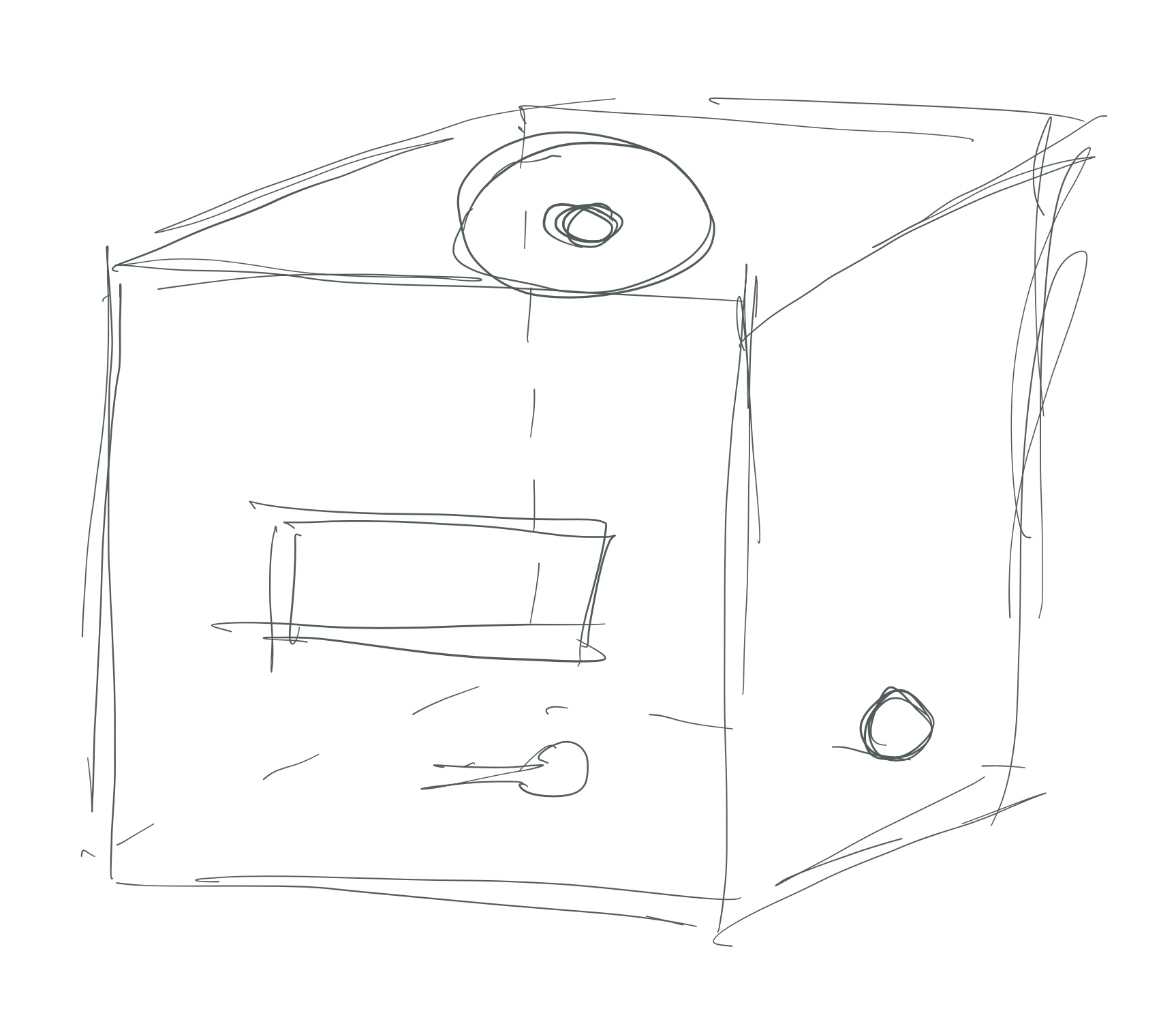
The updated sketch for the final product before fabrication.
In the original ideation, I wanted to use a stepper motor to mimic the clock’s hands, and have it rotate to point to a ring of lit up lights as the timer goes down. However, I soon realized that the stepper motor can take up a large amount of space, which would cause trouble for fabrication, while providing merely decorative effects. So I decided to remove the stepper motor from the project.
The 3D printed decorative object was removed due to similar reasons. Initially, since the device requires the user to put back the pen once the timer is up, I wanted to name the project “Excalibur”, referencing the sword that cannot be pulled out and stays in place. So I wanted to model a “King Arthur” figure to “hold” the pencil in place. However, after starting the model for around 30 minutes, I realize the modeling of this merely decorative character would take significantly more time than I anticipated. Since this shouldn’t be the focus of the project, I decided to remove this component as well.
- Decision Point #2: Fabrication through Laser Cutting instead of 3D Printing
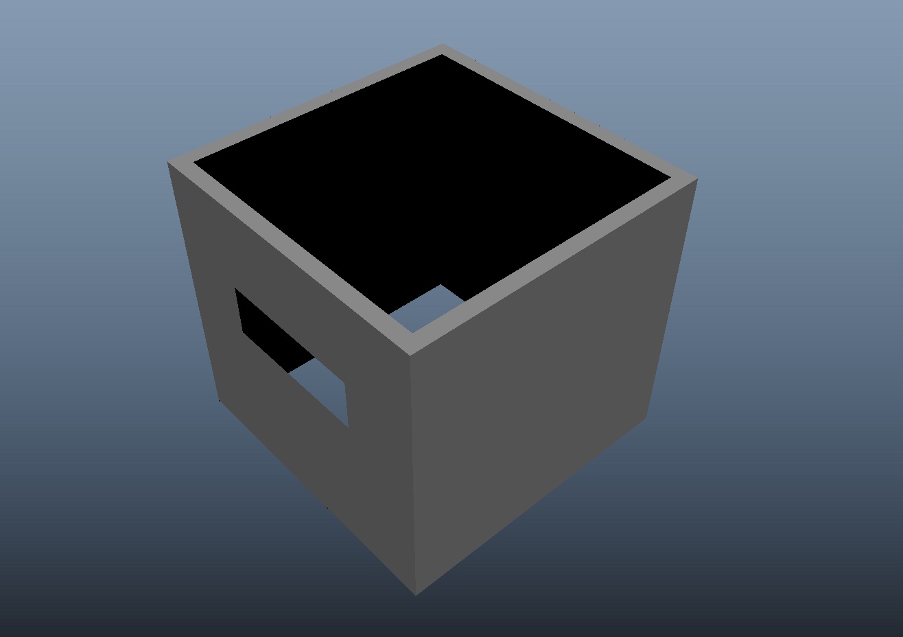
The failed model for 3d printing. The geometry could not fom a valid manifold on the inner side of the box.
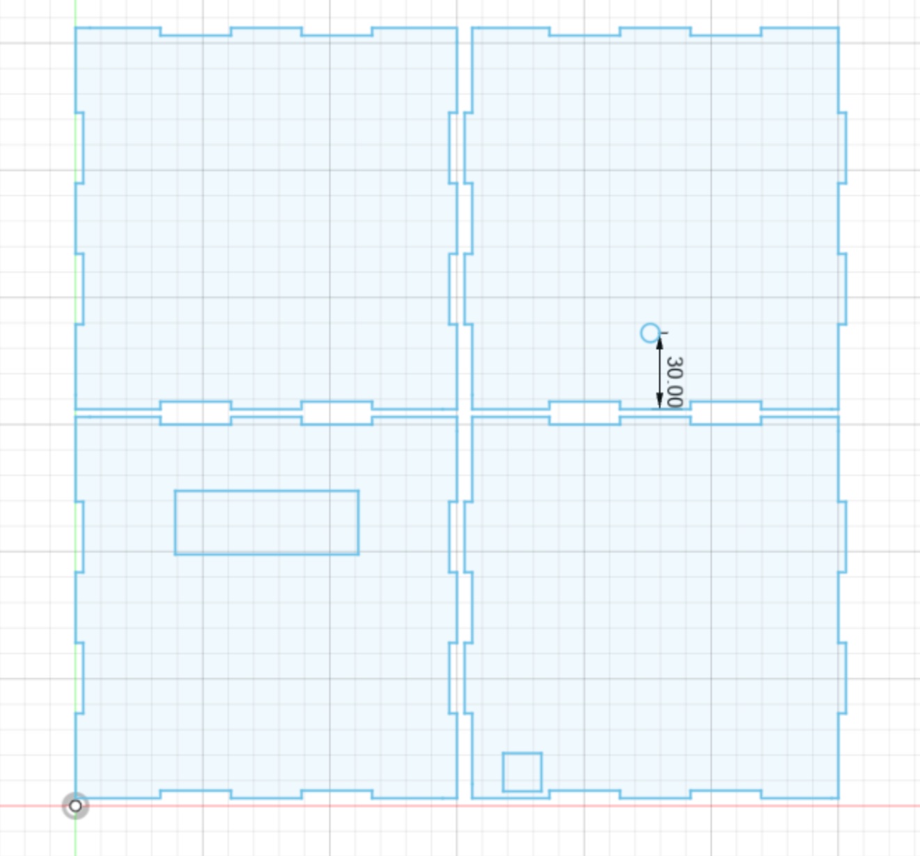
Laser cutting design for the four sides of the box
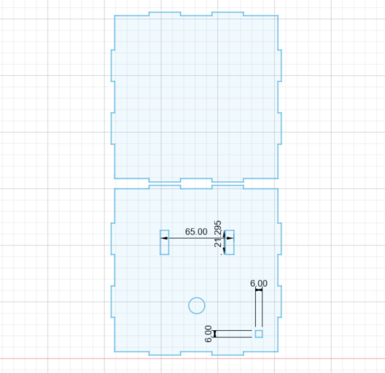
Laser cutting design for the box top/bottom
Initially I wanted to 3D print the outer box, giving it a smooth, plastic-like texture. However, after realizing that printing one small component could take one hour, I realize 3D printing is not the most efficient way, especially if I need to modify the appearance in any way. In addition, it turns out Maya isn’t exactly designed for fabrication modeling. Specifying a certain length in Maya was absolutely pain, and creating a manifold was also a problem. Therefore, I decided to switch to laser cutting the outside box, which turned out to be much more efficient.
- Some More Process Images:
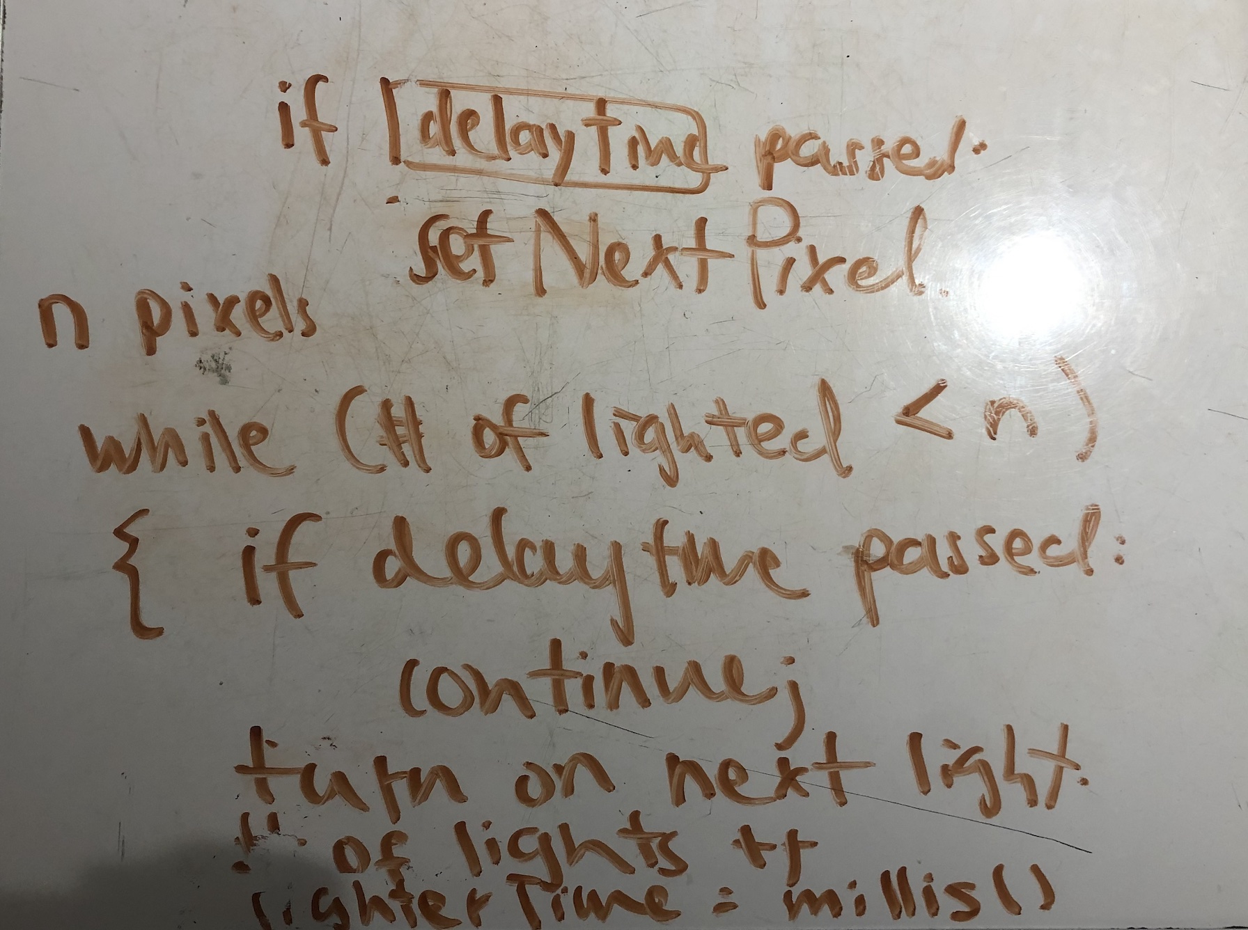
The sample code from NeoPixel library uses a for loop to light up each pixel, which requires the use of delay(). This image illustrates the process of figuring out how to loop through the lights on the NeoPixel ring correctly, so that they light up one by one without interfering the rest of the general loop.
This is the complete functional software prototype before the fabrication design began.
Roughly assembled fabrication with functioning software
Discussion
Overall, I was proud of the final product of this project, as the core functionality from the ideation was fully implemented, and the desired aesthetic design was achieved.
I was pleasantly surprised at how well the appearance turned out. Compared to physical fabrication, I was a lot more confident in the software implementation and electrical wiring. As someone with no experience with fabrication ever, I was dreading making the outer box for the project, and I was prepared for some degree of failure. But after warming up and experimenting with the laser cutting machine for a while, the process of fabrication went much smoother and quicker than I anticipated, and I really enjoyed it. I would definitely use this newly acquired skill in fabrication in the final project and some personal projects as well.
Regarding the in-class review and criticism, I totally agree with the following one: “It seems a bit bulky for something sitting on your desk.” This was my thought as well after assembling the box. I overestimated the space that the wiring would take up and made the box bigger than needed. Although it does not affect the appearance too much, it does cause some nuisance if I were to use this product daily, since it takes up a big chunk of space on my already crowded desk. In the future, I should definitely measure out the space the creation requires in detail, instead of just “eyeballing” how much space it might need.
I also appreciated the comments addressing the aesthetic design, such as “Really nice box and layout of components on the outside. Ah! A face! Cute” and “Looks elegant for your problem and would be a useful incentive to stop working since the lights are so bright.” One of the invited guests from that lecture also stared at the box for quite a while and told me that he “loves the little face”. The fact that the aesthetic design drew a lot of attention actually inspired me to improve the appearance a little bit more before documentation, adding a touch of yellow eyes and red cheeks to “humanize” the box even more. (Special thanks to Nathan for the suggestion of adding the pink cheeks. Absolutely phenomenal. )
I might build a more compact version of this product in the future, with more compact wiring, a smaller Arduino board, and a reduced-sized outer box. This would be a lot more practical to be used more often. In addition, this time I would actually model the disposed “King Arthur”, just to experiment with 3D printing a little bit.
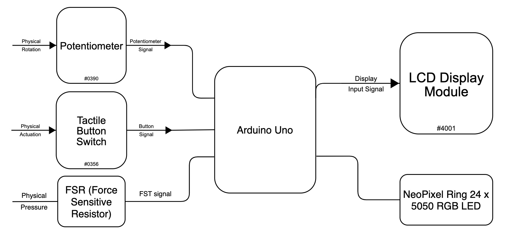
Functional Block Diagram
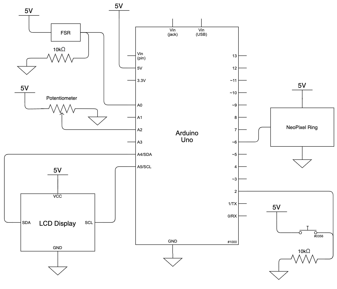
Schematic Diagram
Code
/*
 * Mooonster Timer Box
 *
 * Creator: Bella Liu
 *
 * Description:
 *   The project functions as a timer.
 *   The user can adjust the input time using the potentiometer.
 *   Once the time is adjusted, the user can press the start button to enter "timing session"
 *   The timer would then start, with the remaining time displayed on LCD screen.
 *   The ring of lights would light up, showing how much time has passed since the timer started.
 *   Once the count down is finished, the ring of lights would flash intense red lights,
 *   and the LCD screen would warn the user to put down the pen.
 *   The user must push the pen down the little hole on top to trigger the FSR, thus resetting the timer.
 *
 * Pin Mapping Table:
 *
 *   Arduino pin | description
 *   ------------|-------------
 *   A0            FSR (output)
 *   A2            Potentiometer (input)
 *    2            Tactile Button Switch (input)
 *    6            NeoPixel Ring (input)
 *   SDA           SDA pin - LCD display (input)
 *   SCL           SCL pin - LCD display (input)
 *
 */


#include <Adafruit_NeoPixel.h>
#include <LiquidCrystal_I2C.h>

// Initializations for pins
const int FSR_PIN = A0;
const int POT_PIN = A2;
const int BUTTON_PIN = 2;
const int NEO_PIN = 6;

const int NUMPIXELS = 24; // Popular NeoPixel ring size

// The state of the tactile button
bool buttoned = LOW;
// Indicates whether the timer is in session
bool activated = LOW;
// The potentiometer value
int potVal = 0;
// The number of lights lit up in the ring
int lighted = 0;

// Variables
unsigned long lightTimer = 0;
const int lightWait = 500;

unsigned long LCDtimer = 0;
const int LCDwait = 500;
bool LCDstate = LOW;

unsigned long warningTimer = 0;
const int warningWait = 500;
bool warningState = LOW;

// Initialization of LCD and NeoPixel
LiquidCrystal_I2C screen(0x27, 16, 2);
Adafruit_NeoPixel pixels(NUMPIXELS, NEO_PIN, NEO_GRB + NEO_KHZ800);

void setup() {

  pixels.begin();
  pinMode(POT_PIN, INPUT);
  pinMode(BUTTON_PIN, INPUT);
  pinMode(FSR_PIN, OUTPUT);
  Serial.begin(9600);
  screen.init();
  screen.backlight();

  //welcome smiley face
  screen.setCursor(7,1);
  screen.print("vv");
  delay(5000);

  screen.home();
}

void loop() {

  buttoned = digitalRead(BUTTON_PIN);
  if (buttoned == HIGH) activated = HIGH;
  int minuteMin = 1;
  int minuteMax = 60;
  long interMin = 2500;
  long interMax = 150000;

  // Mapping the potentiometer value to 1-60 minutes
  int minute = map(potVal, 0, 1023, minuteMin, minuteMax);
  // Mapping 1-60 minutes to appropriate intervals for each light to light up
  unsigned int interval = map(minute, minuteMin, minuteMax, interMin, interMax);

  //User is adjusting timer input
  if (activated == LOW)
  {
    pixels.clear();
    pixels.show();
    lighted = 0;

    potVal = analogRead(A2);

    // Display the chosen time
    if ( (millis() - LCDtimer) >= LCDwait ) {
        screen.clear();
        screen.print("timer for:");
        screen.setCursor(0,1);
        screen.print(minute);
        LCDtimer = millis();
    }

  }

  //The button has been pressed, enter "timing session"
  else
  {
    pixels.clear(); // Set all pixel colors to 'off'

    unsigned long current = millis();

    //If time is up, stay in warning state
    if (lighted >= NUMPIXELS){

      // If FSR is triggered, exit warning state and return to user time adjustment phase
      if (analogRead(FSR_PIN) > 5) activated = LOW;

      if ( (millis() - warningTimer) >= warningWait ) {
        warningState = !warningState;
        warningTimer = millis();
      }

      // Flash red light
      if (warningState == HIGH) {
        for (int i = 0; i < NUMPIXELS; i++){
           pixels.setPixelColor(i, pixels.Color(255, 0, 0));
         }
      }
      pixels.show();

      // Display warning messages
      if ( (millis() - LCDtimer) >= LCDwait ) {
          screen.clear();
          screen.print("STOP! PEN DOWN!");
          LCDtimer = millis();
      }

    }

    // For RGB values
    int green = 240;
    int blue = 0;
    int red = 0;

    //If time is not up, light up the lights accordingly
    while (lighted < NUMPIXELS){

      if ( (millis() - lightTimer) >= interval) {

        // Change the color of the each light
        blue += 10;
        green -= 10;
        red += 5;
=
        pixels.setPixelColor(lighted, pixels.Color(red, green, blue));
        lighted ++;
        lightTimer = millis();
      }
      pixels.show();

      // Calculate the times
      int passedSec = ((millis()-current)/1000);
      int displaySec = passedSec % 60;
      int passedMin = passedSec / 60;

      // Display the timez on LCD screen
      if ( (millis() - LCDtimer) >= LCDwait ) {
          screen.clear();
          screen.print("Total");
          screen.setCursor(0,1);
          screen.print(minute);
          screen.setCursor(6,0);
          screen.print("Counting");
          screen.setCursor(6,1);
          screen.print(passedMin);
          screen.setCursor(8,1);
          screen.print(":");
          screen.setCursor(9,1);
          screen.print(displaySec);
          LCDtimer = millis();
      }
    }
  }
}