This device works to hold my phone while I am studying or doing work, preventing me from distracting myself by using my phone while I should be focusing on the task at hand.
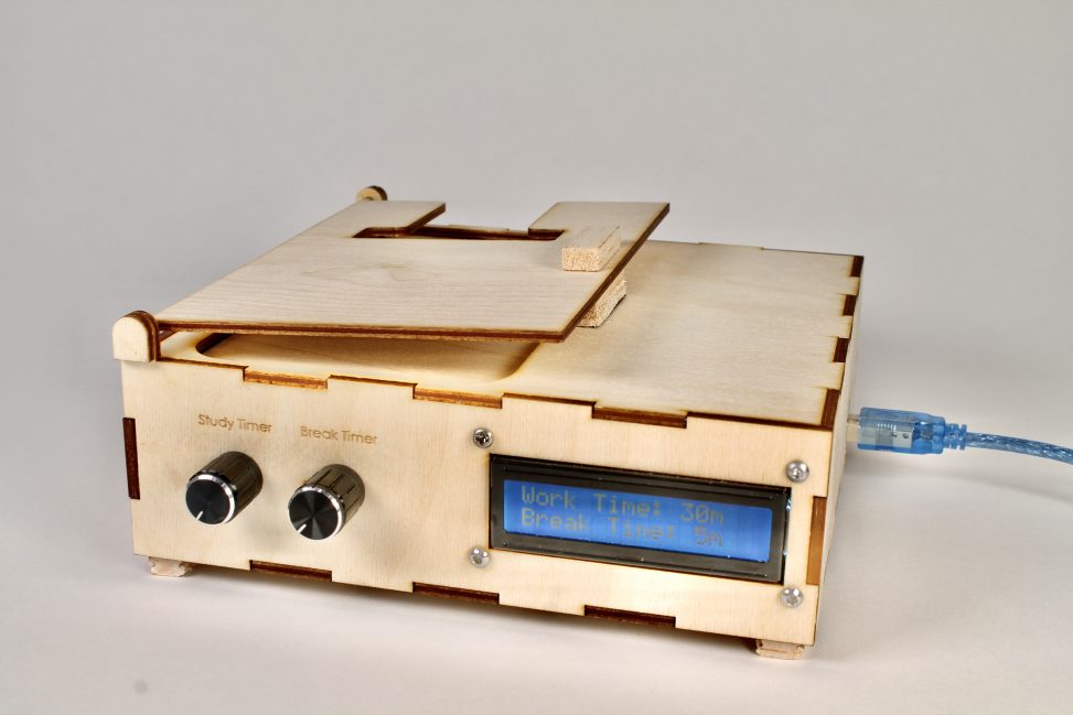
Use the knobs to set the work time and break time before beginning the study session.
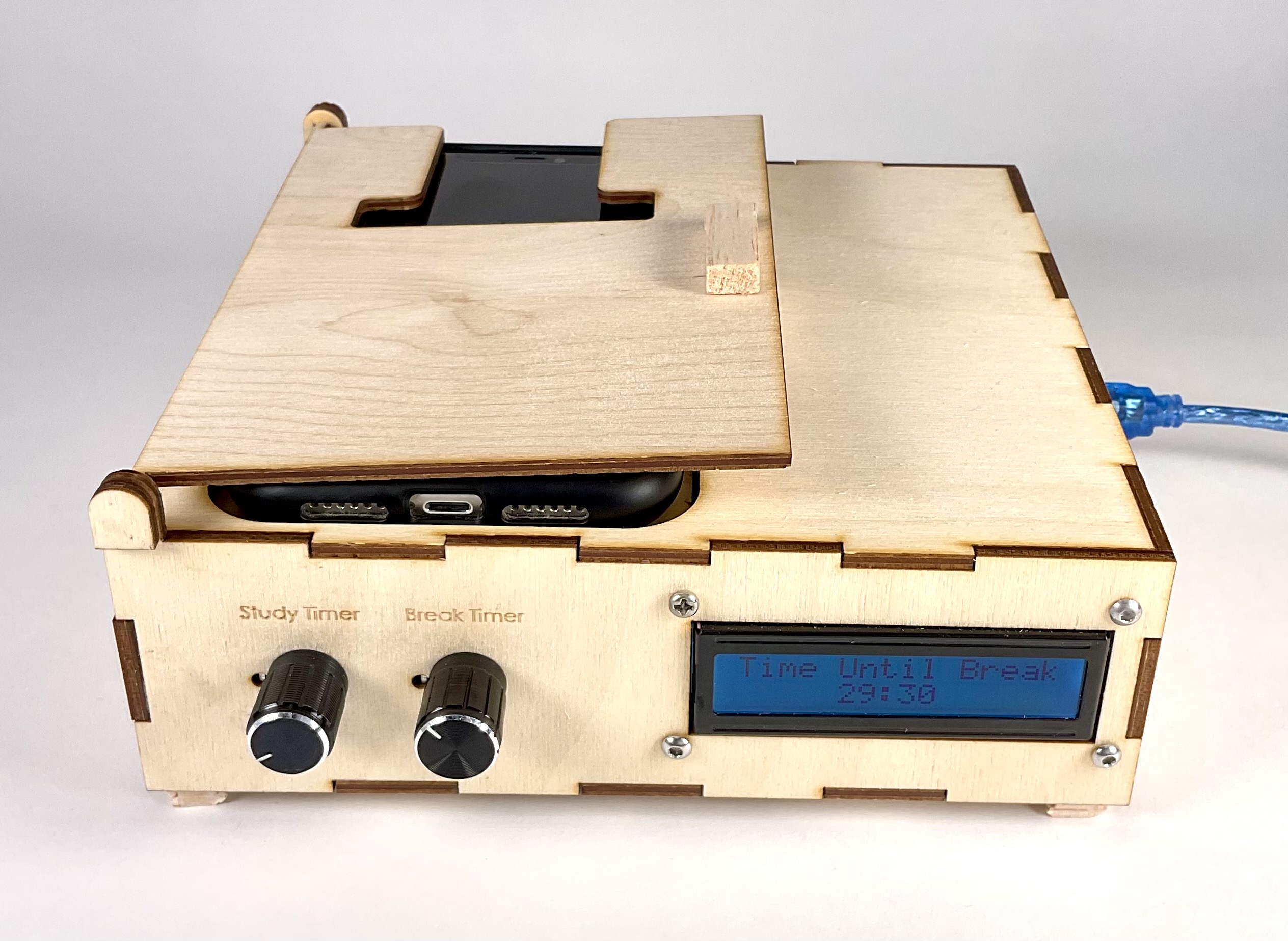
Place your phone in the casing to begin your study session. An FSR Pressure Sensor detects the presence of the phone. The timer will start to count down automatically.
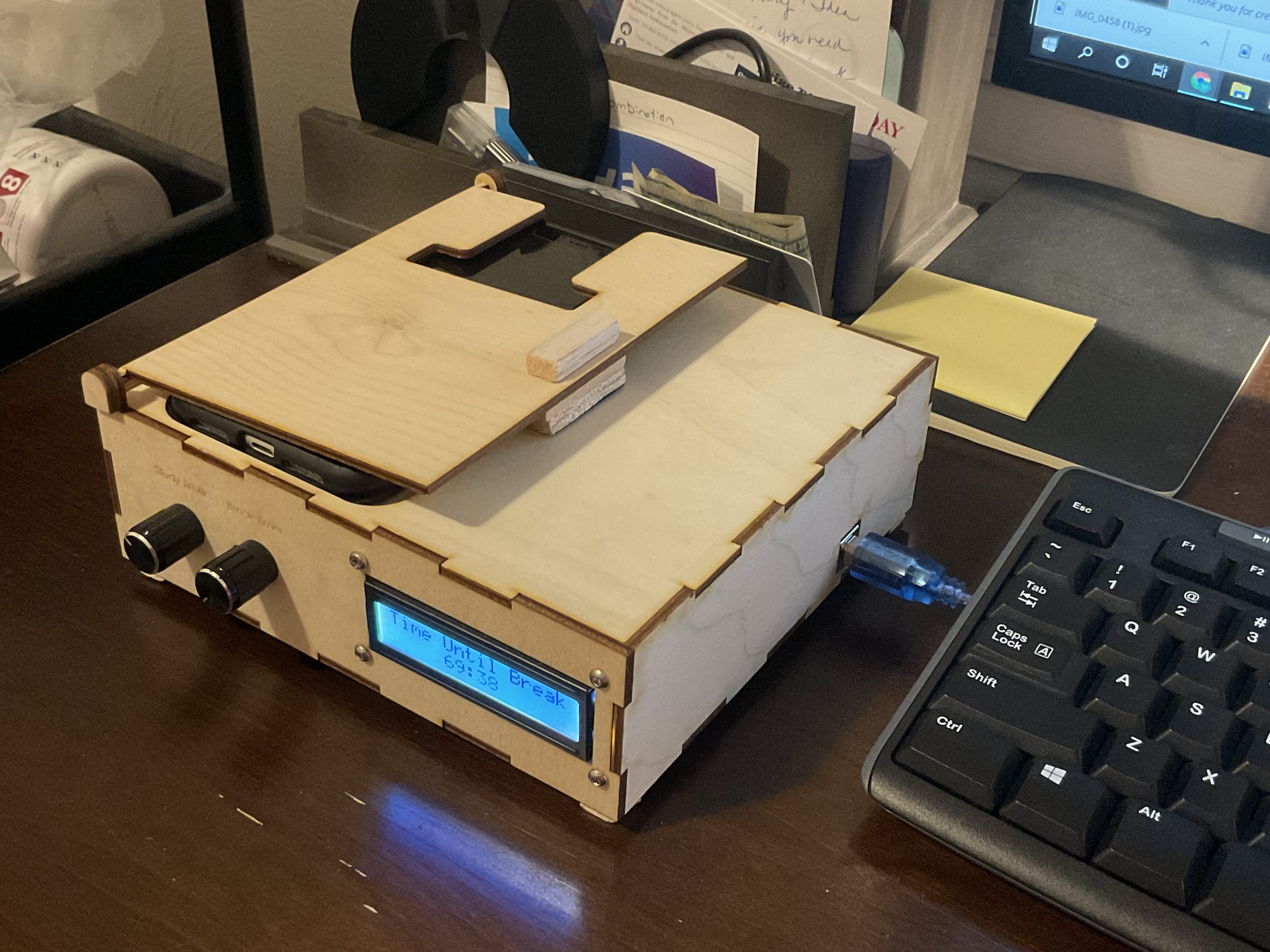
Overall Photo
The device holds your phone while you work for an amount of time set by the user. When time is up, a set break will begin, allowing the user to take their phone without penalty.
Detail Photos
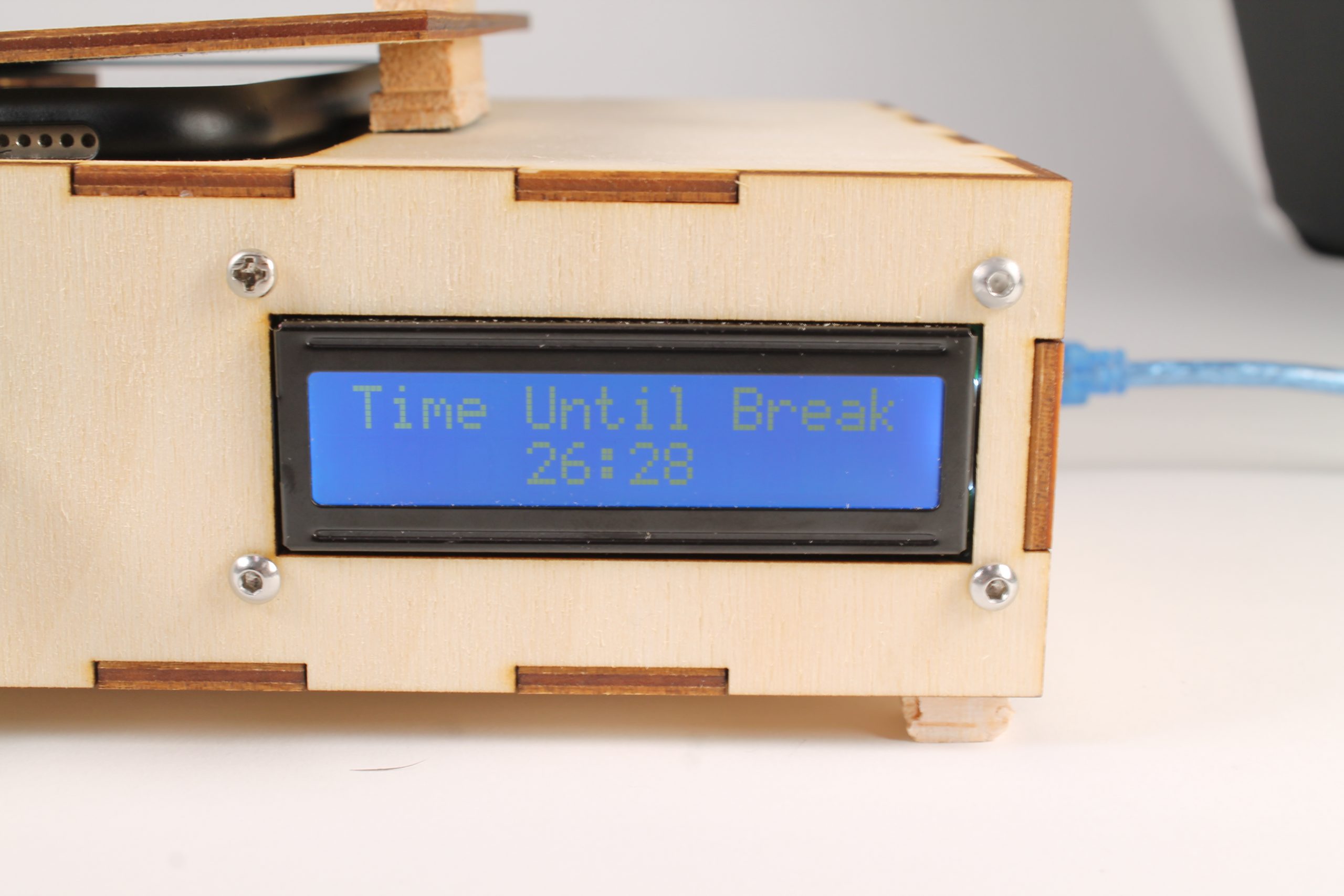
The timer counts down on the LCD Screen before automatically switching to the break timer.
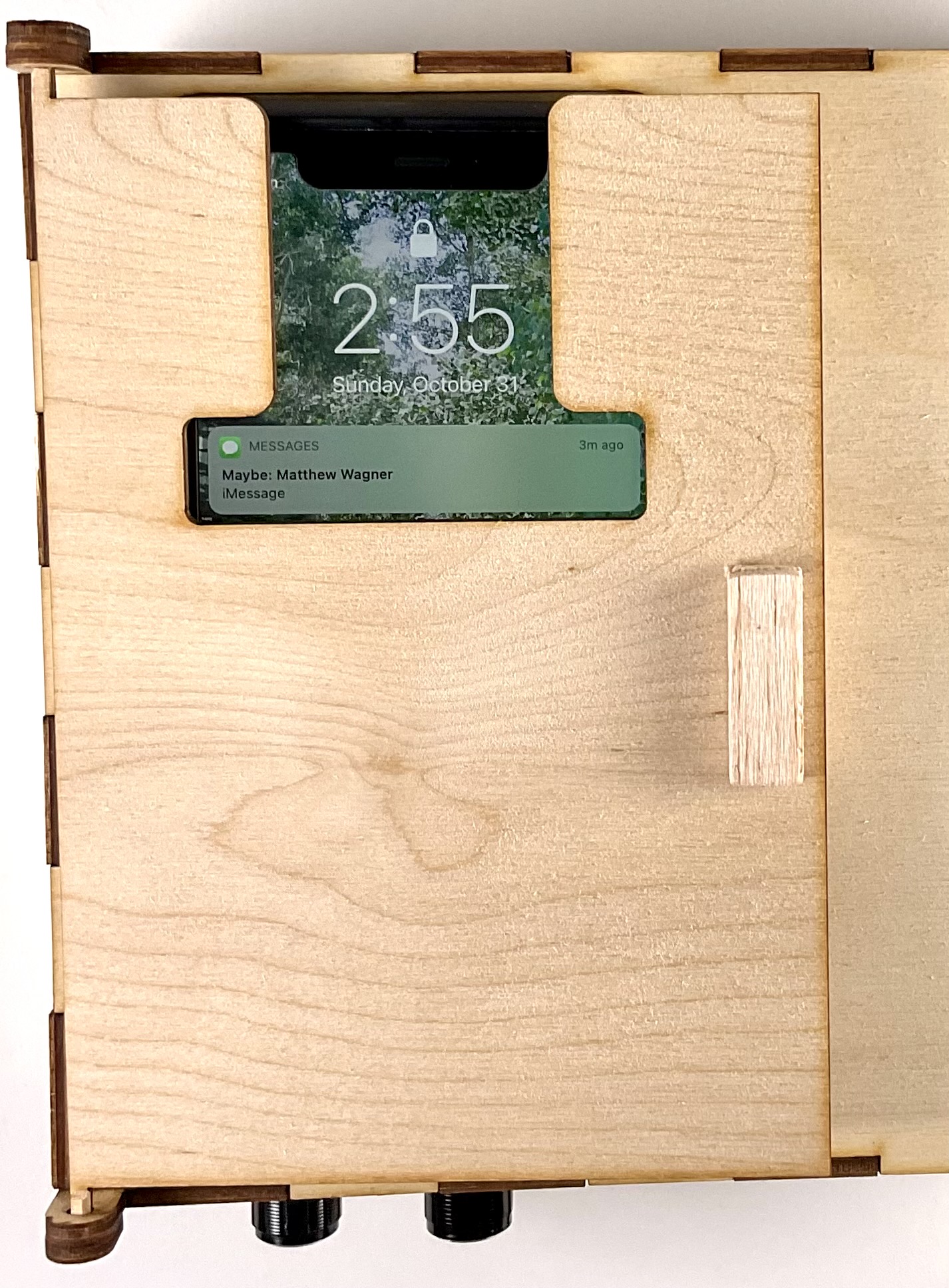
When the door is closed, the time and the top notification is still visible to the user, in case the user receives a notification they believe is an emergency.
Usage Photos
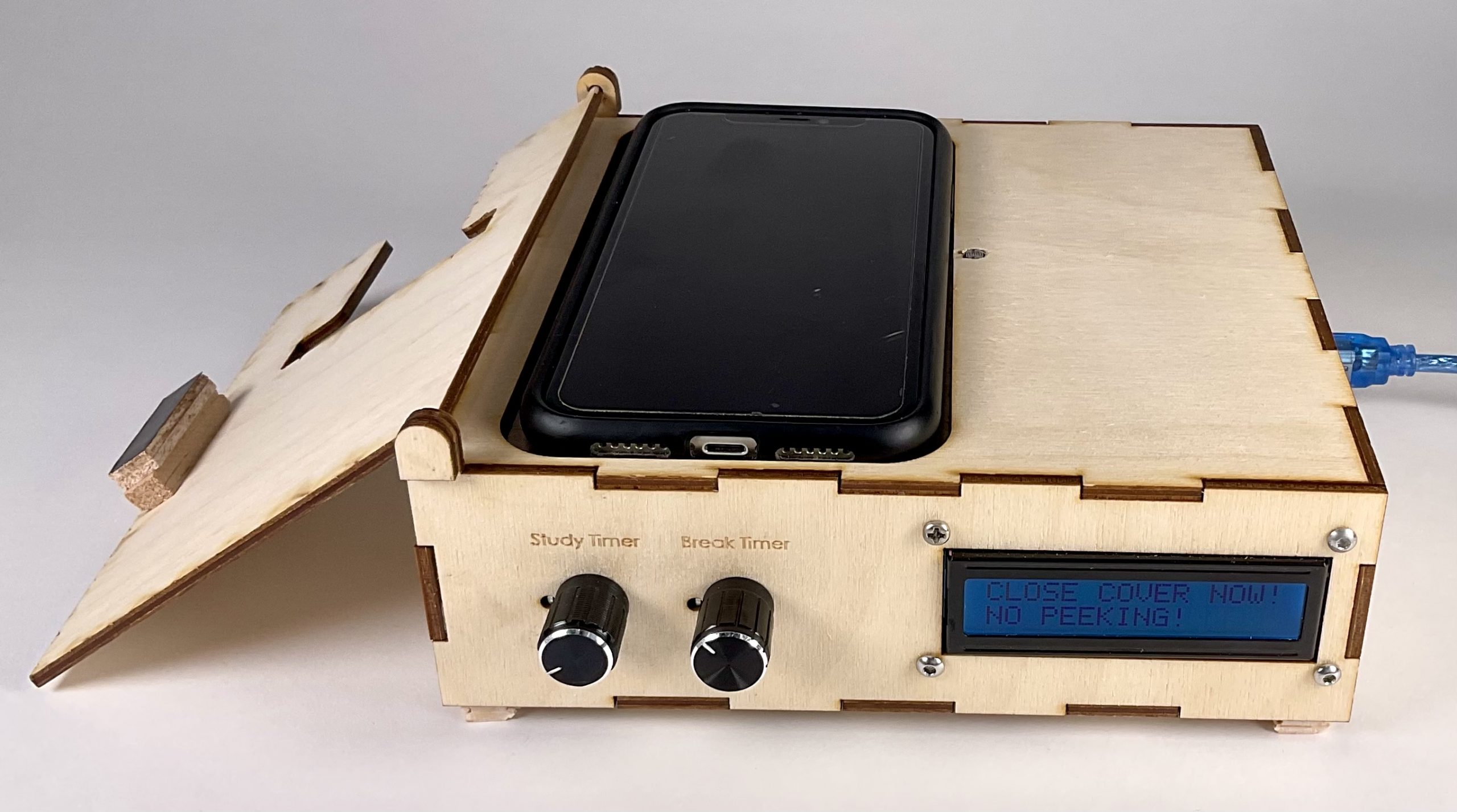
The user may open the door to quickly check their phone. However, if the photoresistor to the right of the phone detects that the door is open for more than 10 seconds, an alarm triggers and the message shown above is displayed on the LCD screen.
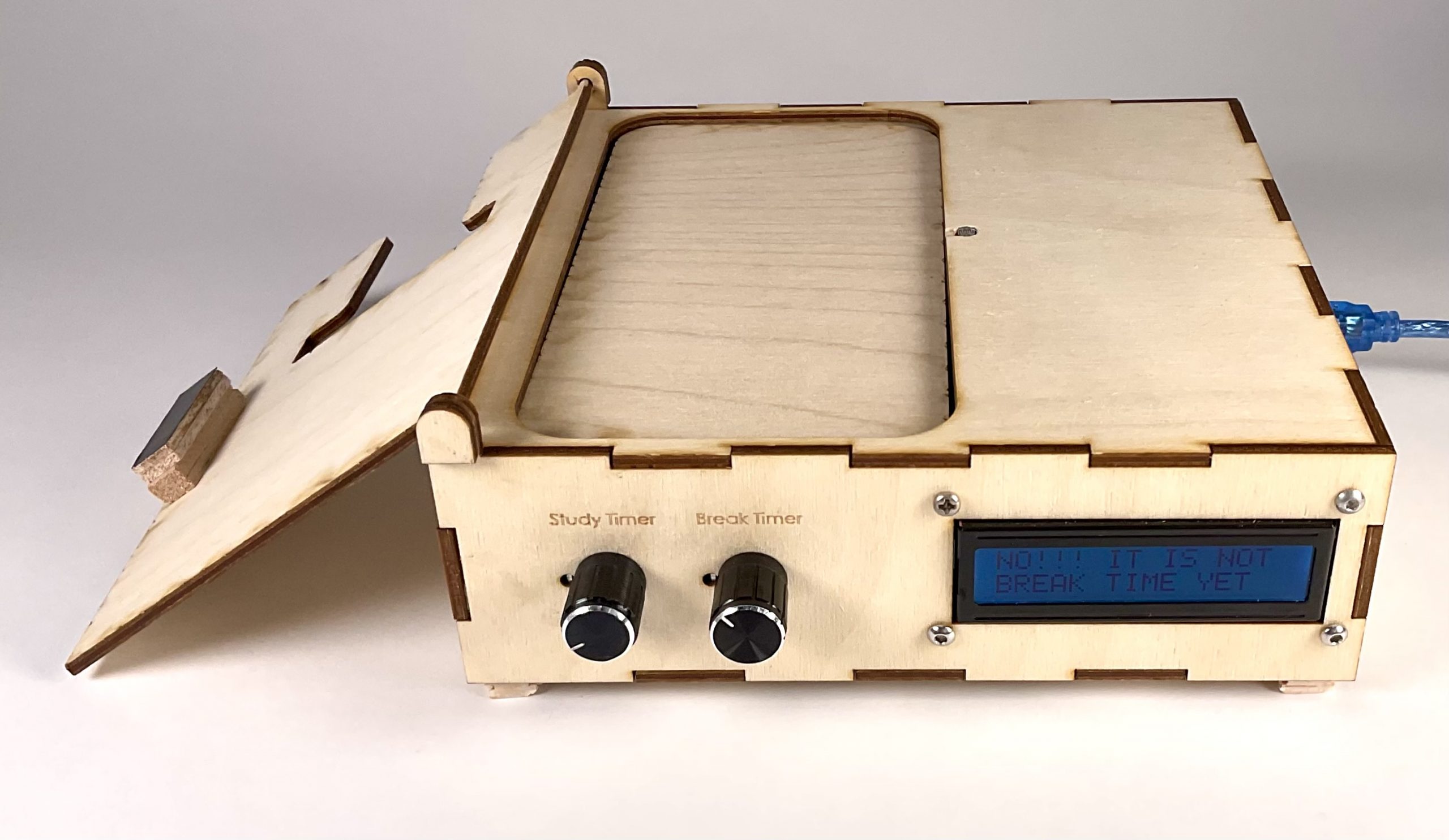
If the phone is removed before the break begins, the device will set off an alarm once again until the phone is put back. The timer doesn’t count down in this state.
Here is a picture of my device in action while I write this report!
Process and Review
During this project, I had to make many decisions that significantly changed the outcome of my design and project as a whole.
One challenge I ran into early was that my phone did not activate the pressure sensor. My whole idea thus far had relied on the phone activating the pressure sensor, and this realization frustrated me early on. With some testing, I knew that the pressure sensor did work when I used my finger to apply pressure, just not when my phone rested on top of it.
As a result, I concluded that the pressure applied needed to be concentrated. Since my phone is wider than the sensor, the weight of the phone was too distributed to impact the resistance in the FSR.
To solve this problem, I created the following 3D printed part to hold up a wide body, and concentrate its weight in a smaller location:
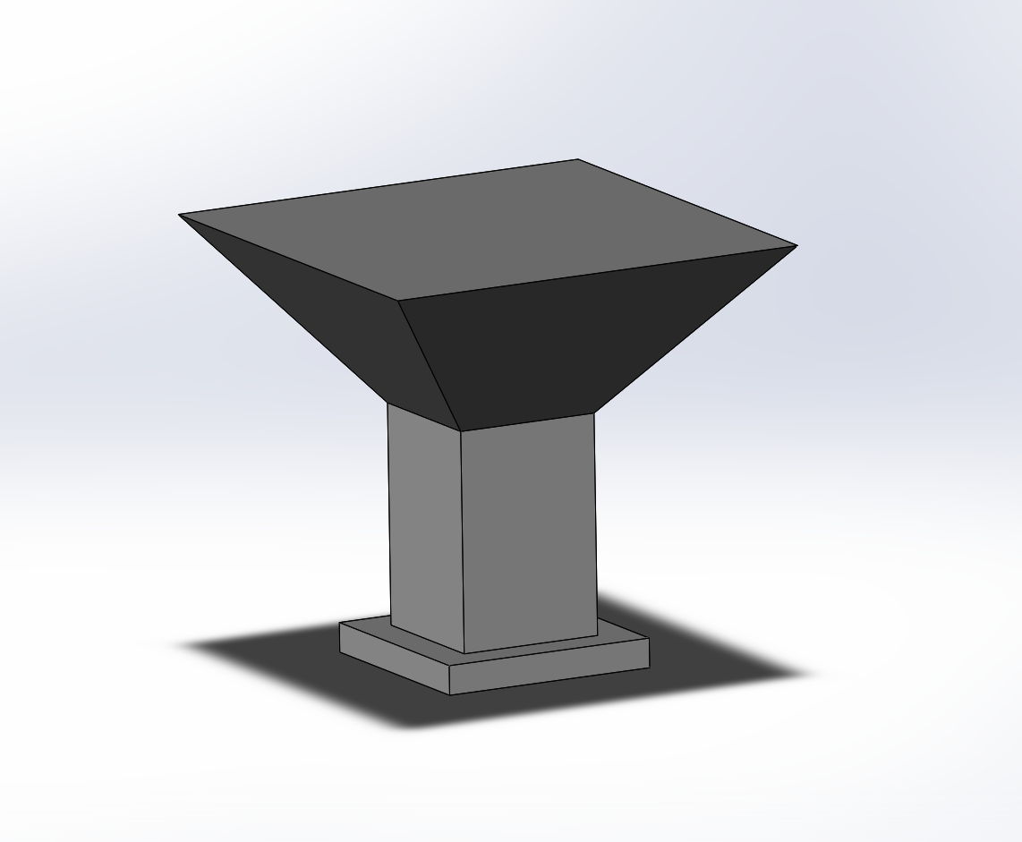
This part concentrates pressure due to weight in a small area. The part was 3D printed using the IDeATe Skylab.
Since the phone still could not rest solely on this part, I had to attach it to the piece of wood that would act as the casing for the phone. In order to prevent the assembly from falling over, I used springs in each of the four corners for stability. This worked well to hold up the corners and allow for slight vertical displacement when the phone applies pressure to the assembly, which then applies pressure to the FSR sensor, activating my device.
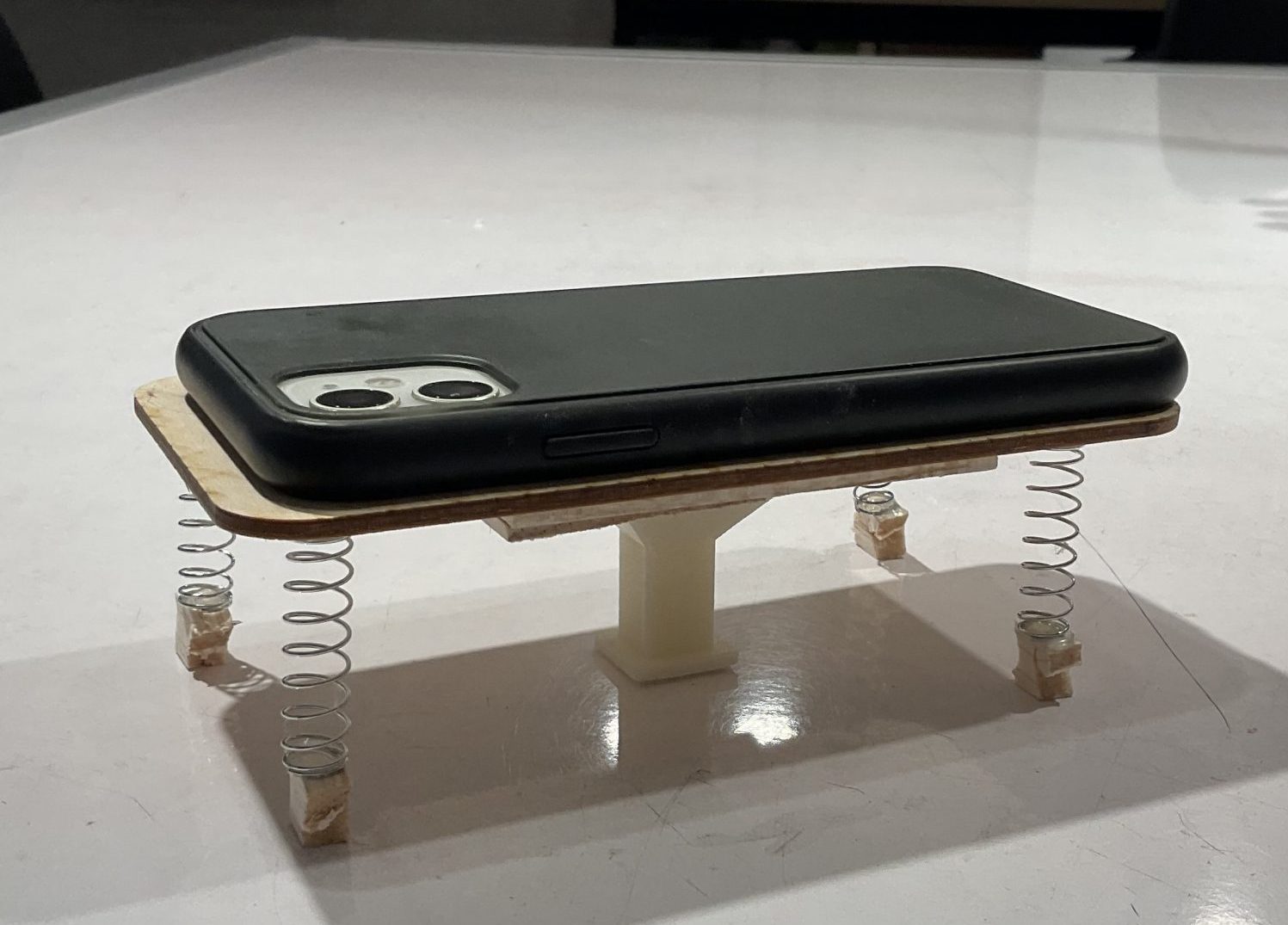
This design allows for stability of the phone and activation of the FSR sensor when the phone is placed into the device.
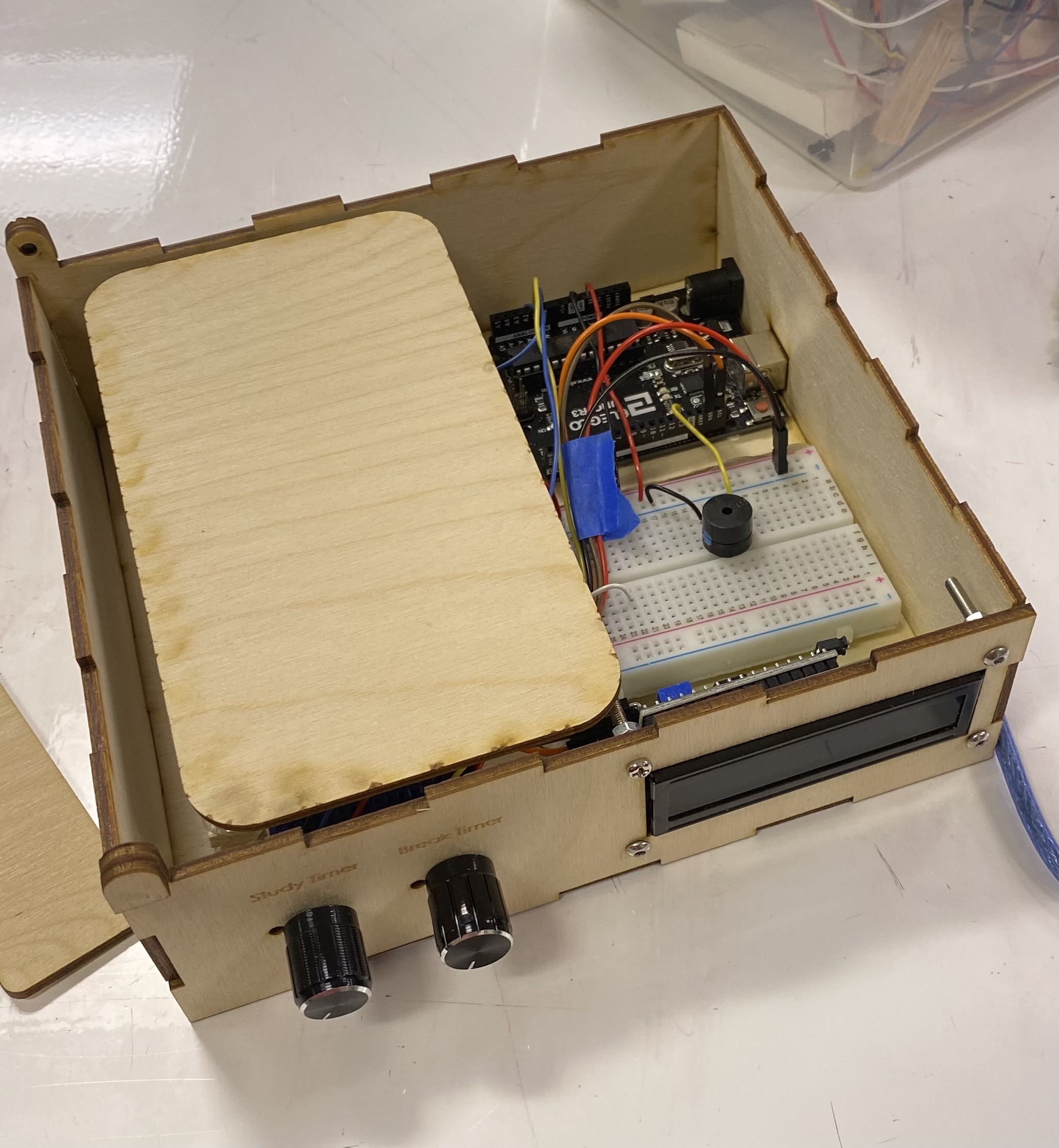
The assembly was placed in the middle of the box in a strategic spot to avoid other wires and electrical components.
Another challenge I ran into during the design process was what to do with the door that covered my phone during work time. Since I cut the entire box out of wood, the axels that the door hinges on are actually rectangular. To make them fit in the holes of the hinge, I had to sand the corners of the rectangular cut out until they allowed the door to open and close smoothly. I am proud of this work around, as it allowed me quickly adapt my prior work with out the use of additional materials or design components.
I knew I wanted to have some visibility so that the user could identify if a notification was an emergency that needed a response. However, with the door there, there was nothing discouraging the user from just opening the door to use their phone while still activating the pressure sensor. To combat this, I wanted to somehow sense if the door was closed or not to punish the user when the door was open for too long by ringing the alarm that sounds when the phone is removed from the device.
I felt that this discouragement was sufficient enough for me, as the buzzer used makes a really loud sound at a pitch I am fairly sensitive to. I will defiantly be motivated to close the door as soon as it starts going off.
I wrestled with a few ideas on how to sense if the door was closed or not. I ended up using a photoresistor to detect a change in light brightness when the door closes. The photoresistor would stick out on the top of the box, next to the phone as shown below. This way it is covered when the door is closed and is un-intrusive to the user.
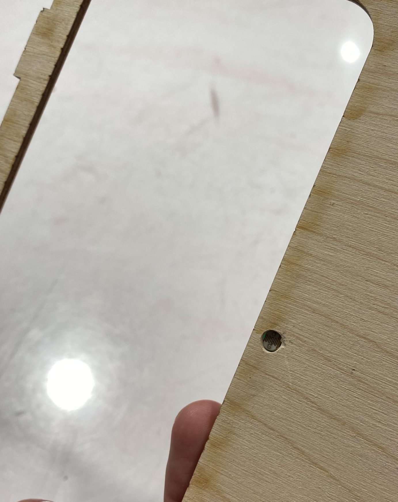
The photoresistor peeks out from a hole drilled into the top of my casing.
To wire and attach the photoresistor to the top of my box, I soldered it to a protoboard, along with the rest of the wiring needed to power the photoresistor.
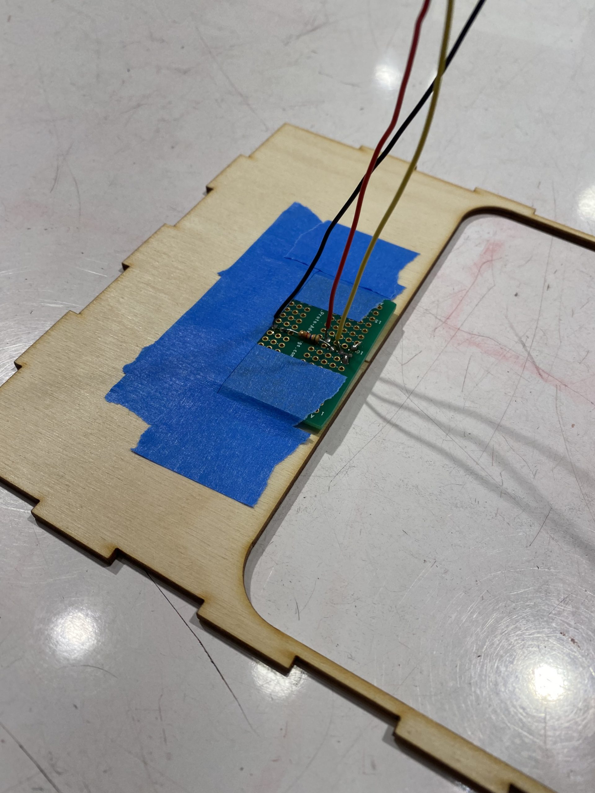
A resistor, output connection, power and ground are soldered to the protoboard attached under the top of the box. Tape used early on.
Despite my efforts, the photoresistor value of the door being closed was inconsistent in different lighting environments since the door was not completely flush with the top of my box. To combat this, I glued some scrap wood on the edge of the door until it was flush with the top of my box, over the photoresistor. I also placed black electrical tape on the surface of the scrap wood to further darken the area the photoresistor sensed when closed. This solution worked well and made the values produced by the photoresistor much more consistent despite the brightness of the room.
Additional Process Pictures
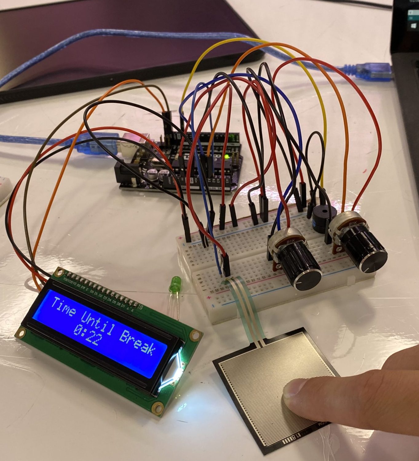
In the prototype stages, only my finger could activate the pressure sensor, not my phone. Nonetheless, I was proud of myself for wiring and coding the interaction between the potentiometer knobs, FSR, Buzzer and LCD Screen without additional assistance.
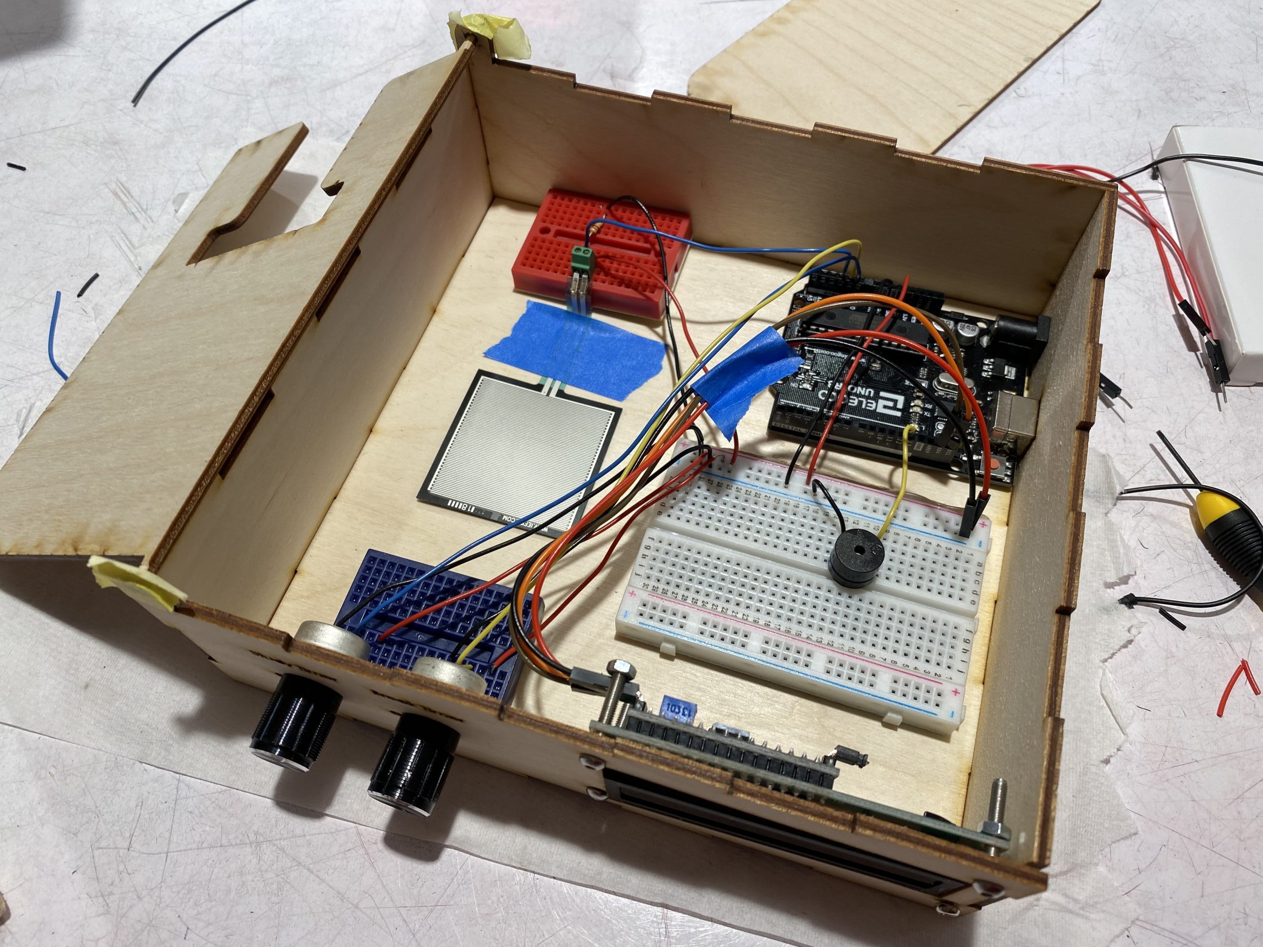
I was challenged to organize the wiring and components in the box in an efficient and effective way.
While I knew that soldering all of the electrical components would make better connections, I ended up doing so sparingly. While all wiring for the FSR sensor and the photoresistor are soldered in the final product, I determined it was unnecessary to solder the potentiometers and the buzzer. Since I am a novice at soldering, I did not want to risk damaging the potentiometers during that process, a consequence that can occur if done without precision. Also, the breadboard provided a great base that helped control the height of the potentiometer, which helped when designing the box to encase them in. Since the box only sits on my desk and the wires are not intended be thrown around, I deemed it less important to solder each component, and used that time to improve the ergonomics and sleek design of my device.
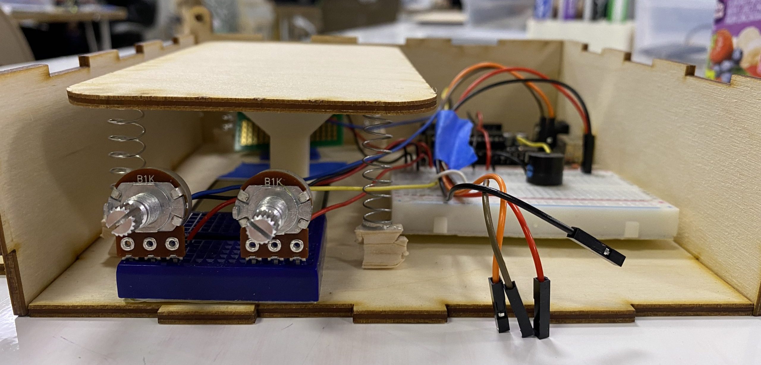
Ensuring electrical connections were sufficient was a big challenge and required careful consideration of elegance, safety, and my time.
Discussion
When presenting my project to the class, I received some great critiques and feedback. One piece of feedback I received was that I should have had the buzzer quickly go off to alarm the user that they have transitioned into the break time from the work time. This is a great idea and something that I had originally thought of during the prototyping phase. However, I ended up forgetting to incorporate the idea, and it completely slipped my mind until I was given feedback. Additionally, it was suggested that I added an emergency stop to my device, so that it would not alarm when I discontinued use in the event of an emergency. While I also considered this, I decided that if there was a true emergency, I could just unplug the device from my computer. I know that I would not abuse this power, as it defeats the whole purpose of what I am trying to do. If my phone is in my assistive device, it will remind me of my goal to keep working until the break. Despite these minor shortcomings, I am proud of the project that I created. Not having a partner who knew electronics left me responsible for figuring out the unknown by myself and challenged me to learn and grow as an engineer. I exceeded my personal expectations and I believe that I delivered a complete and robust project. I learned so much during this project, including a better understanding of electrical components, soldering, simple algorithms and how they are integrated with mechanical design. The project challenged me to think about problems using different perspectives and challenged me to solve those problems in a creative and elegant way. While it is safe to say that this will be the final version of my device for now, there are a few modifications that I could make to clean up the user experience. For example, the buzzer indicating the transitions as mentioned above. I would also like to add a button that takes the user back to the home screen to let them set new work and break time durations without having to unplug the device. These additions would be nice, but are not significant enough to require iteration in order to use the device. It works well for me and my need!
Block Diagram
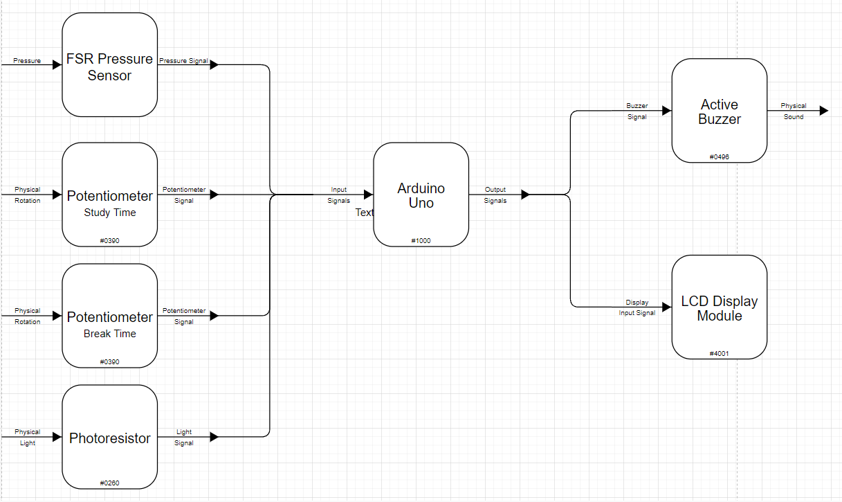
The block Diagram generalizes the electric schematic of the assistive device. This is helpful for early ideation and visualizing the flow of the wiring.
Electrical Schematic
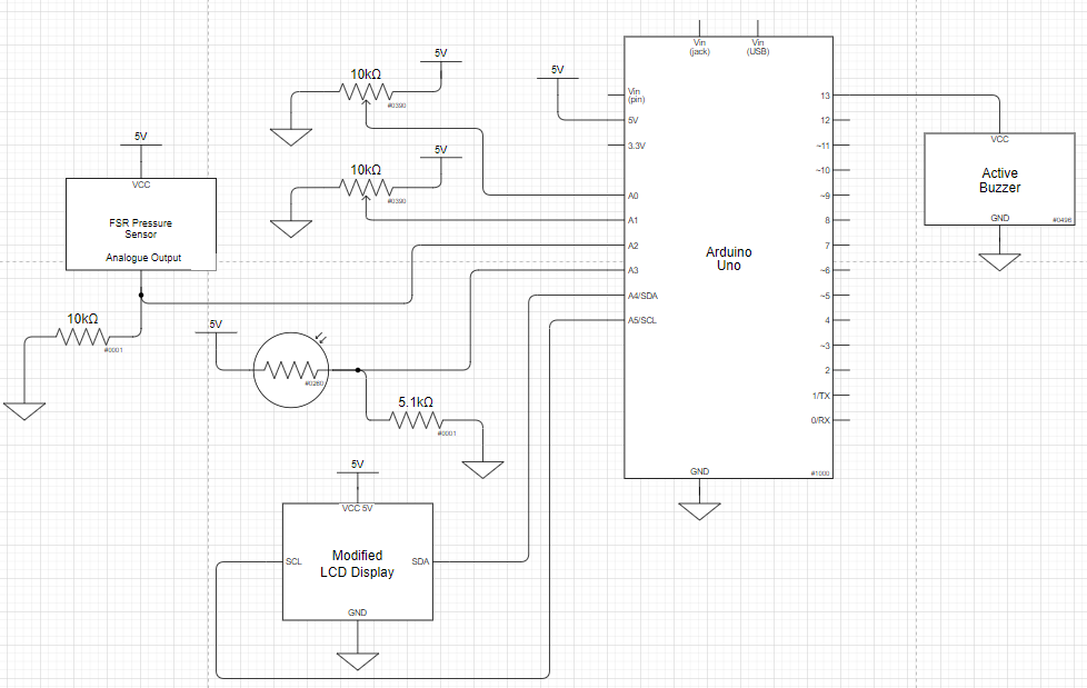
The schematic better represents the wiring of my project including which pins on the Arduino I used.
Code
/* Study Time Phone Jail
   By Matthew Wagner
   60-223 Introduction to Physical Computing
   Professor Robert Zacharias
   Due 11/2/2021

   This project helps someone stay focused when studying by
   trapping their phone in the 'Jail', preventing use. The
   user can set how long they want to work and take a break
   for. While working, if the phone is removed, or the door
   cover is opened for too long, the device alarms the user
   to return to their task and put the phone back. The user
   gets a set break time after each work time.

   Pin mapping:
     Arduino pin | role   | description
     ------------|--------|-------------
     A0            input    potentiometer (Sets Work Time)
     A1            input    potentiometer (Sets Break Time)
     A2            input    FSR Pressure Sensor (Square)
     A3            input    photoresistor
     13            output   active buzzer
     SDA           output   LCD Screan (modified)
     SCL           output   LCD Screen (modified)

     I^2C LCD: Modified code from Robert Zacharias
               Used Library by Frank de Brabender,
               based on work from DFRobo (Nov. 2018)

     millis:   Modified code from Robert Zacharias
 */


/////////////////////////////
//        LIBRARIES        //
/////////////////////////////
#include <Wire.h>
#include <LiquidCrystal_I2C.h>

// create LCD Display called "screen"
LiquidCrystal_I2C screen(0x27, 16, 2);

byte frowny[] = {
  B00000,
  B11011,
  B11011,
  B00000,
  B00000,
  B01110,
  B10001,
  B00000
};


// track time passed using: millis()
const unsigned long DISPUPDATETIME = 500;
unsigned long lastUpdate = millis();


// FSR
const int FSRPIN = 2;
int fsrReading;

// photoresistor
const int PHOTOPIN = 3;
int photoVal;

// active buzzer
const int BUZZERPIN = 13;
int screenPeekTime = 0;

// User interface initial values/ settings:
int workTime = 45;
int breakTime = 5;
int seconds = 0;
bool phoneSensed = false;
bool working = false;
bool onBreak = false;
bool buzzerOn = false;
bool screenCoverClosed = false;

void setup() {
  // work time potentiometer
  pinMode(A0, INPUT);

  // break time potentiometer
  pinMode(A1, INPUT);

  // buzzer
  pinMode(BUZZERPIN, OUTPUT);
  digitalWrite(BUZZERPIN, LOW);

  // photoresistor
  pinMode(PHOTOPIN, INPUT);

  // initialize the screen (only need to do this once)
  screen.init();

  // turn on the backlight to start
  screen.backlight();

  // set cursor to home position, i.e. the upper left corner
  screen.home();
}

void loop() {

  // let user set work and break time before starting work
  if (!working && !onBreak){
    // read potentiometer value, map to work time
    workTime = map(analogRead(A0), 0, 1023, 6, 36);
    // multiply by 5 to only display 5 minute increments between
    // 30 mins and 3 hrs
    workTime = 5 * workTime;

    // read potentiometer value, map to break time
    breakTime = map(analogRead(A1), 0, 1023, 1, 6);
    // multiply by 5 to only display 5 minute increments between
    // 5 and 30 mins
    breakTime = 5 * breakTime;

    if (millis() - lastUpdate >= DISPUPDATETIME){

      screen.clear();

      // display work time
      screen.print("Work Time: ");
      screen.setCursor(11, 0);
      screen.print(workTime);
      screen.print("m");


      // display break time
      screen.setCursor(0, 1);
      screen.print("Break Time: ");
      screen.setCursor(12, 1);
      screen.print(breakTime);
      screen.print("m");

      screen.home();

      lastUpdate = millis();
    }
  }

  // keep a timer while working
  else if (working && !buzzerOn && millis() - lastUpdate >= 2 * DISPUPDATETIME){
    screen.clear();

    // display time
    screen.print("Time Until Break");
    screen.setCursor(5, 1);
    screen.print(workTime);
    screen.print(":");
    if (seconds < 10){
      screen.print("0");
    }
    screen.print(seconds);
    screen.home();

    // update timer
    if (seconds == 0){
      if (workTime == 0) {
        working = false;
        onBreak = true;
      }
      else{
        workTime = workTime - 1;
        seconds = 59;
      }
    }
    else{
      seconds = seconds - 1;
    }

    // check if user is peeking
    if (!screenCoverClosed){
      screenPeekTime = screenPeekTime + 1;
    }
    lastUpdate = millis();
  }


  // keep a timer while on break
  else if (onBreak && millis() - lastUpdate >= 2 * DISPUPDATETIME){
    screen.clear();

    // display time
    screen.print("On Break for:");
    screen.setCursor(5, 1);
    screen.print(breakTime);
    screen.print(":");
    if (seconds < 10){
      screen.print("0");
    }
    screen.print(seconds);
    screen.home();

    // update timer
    if (seconds == 0){
      if (breakTime == 0) {
        // back to work when break is over
        working = true;
      }
      else{
        breakTime = breakTime - 1;
        seconds = 59;
      }
    }
    else{
      seconds = seconds - 1;
    }

    lastUpdate = millis();
  }

  // sensor
  fsrReading = analogRead(FSRPIN);

  if(fsrReading > 500){
    phoneSensed = true;
    digitalWrite(BUZZERPIN, LOW);
    buzzerOn = false;
    if (!working && !onBreak){
      working = true;
      onBreak = false;
      seconds = 0;
    }
    // reset work time and break time for next session after break
    else if (working && onBreak){
      onBreak = false;
      // read potentiometer value, map to work time
      workTime = map(analogRead(A0), 0, 1023, 6, 36);
      // multiply by 5 to only display 5 minute increments between
      // 30 mins and 3 hrs
      workTime = workTime = 5 * workTime;

      // read potentiometer value, map to break time
      breakTime = map(analogRead(A1), 0, 1023, 1, 6);
      // multiply by 5 to only display 5 minute increments between
      // 5 and 30 mins
      breakTime = 5 * breakTime;
    }

    // buzz if user is peeking for too long
    else if (working && !screenCoverClosed && screenPeekTime >= 12){
      digitalWrite(BUZZERPIN, HIGH);
      buzzerOn = true;
      if (millis() - lastUpdate >= DISPUPDATETIME){
        screen.clear();
        screen.print("CLOSE COVER NOW!");
        screen.setCursor(0,1);
        screen.print("NO PEEKING!");
        screen.home();
        lastUpdate = millis();
      }
      }
  }
  else{
    phoneSensed = false;
    // buzz if break ends and phone isn't sensed
    if (working && onBreak){
      digitalWrite(BUZZERPIN, HIGH);
      buzzerOn = true;
      if (millis() - lastUpdate >= DISPUPDATETIME){
        screen.clear();
        screen.print("BREAK IS OVER!");
        screen.setCursor(0,1);
        screen.print("PUT PHONE BACK!");
        screen.home();
        lastUpdate = millis();
      }
    }
    // buzz if phone isn't sensed while working
    else if (working && !onBreak){
      digitalWrite(BUZZERPIN, HIGH);
      buzzerOn = true;
      if (millis() - lastUpdate >= DISPUPDATETIME){
        screen.clear();
        screen.print("NO!!! IT IS NOT");
        screen.setCursor(0,1);
        screen.print("BREAK TIME YET");
        screen.home();
        lastUpdate = millis();
      }
      }
  }

  // read photoresistor
  photoVal = analogRead(PHOTOPIN);
  if (photoVal <= 300){
    screenCoverClosed = true;
    screenPeekTime = 0;
    digitalWrite(BUZZERPIN, LOW);
    buzzerOn = false;
  }
  else {
    screenCoverClosed = false;

  }
  }