This device is intended to let everyone around you know when you are working or not so that you are able to stay on task.
This is the toaster switching from free time mode to work mode. You see once work mode is on, the lights starts to flash which is from the noise in the room. The linear actuator has to complete its’ movement before the mode properly switches.
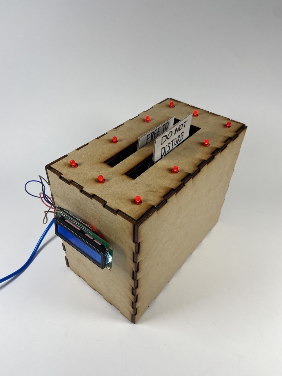
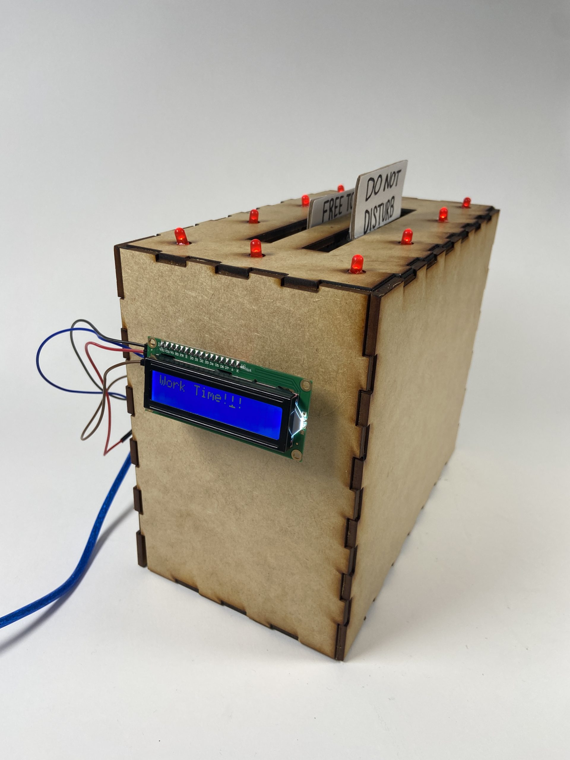
Main Photo For Scale: The toaster has a “Do Not Disturb” sign and a “Free To Talk” sign at the top. 10 LEDs on the top. An LCD that says “Break Time!” or “Work Time!”. A switch to start timer and sound sensor are in the back.
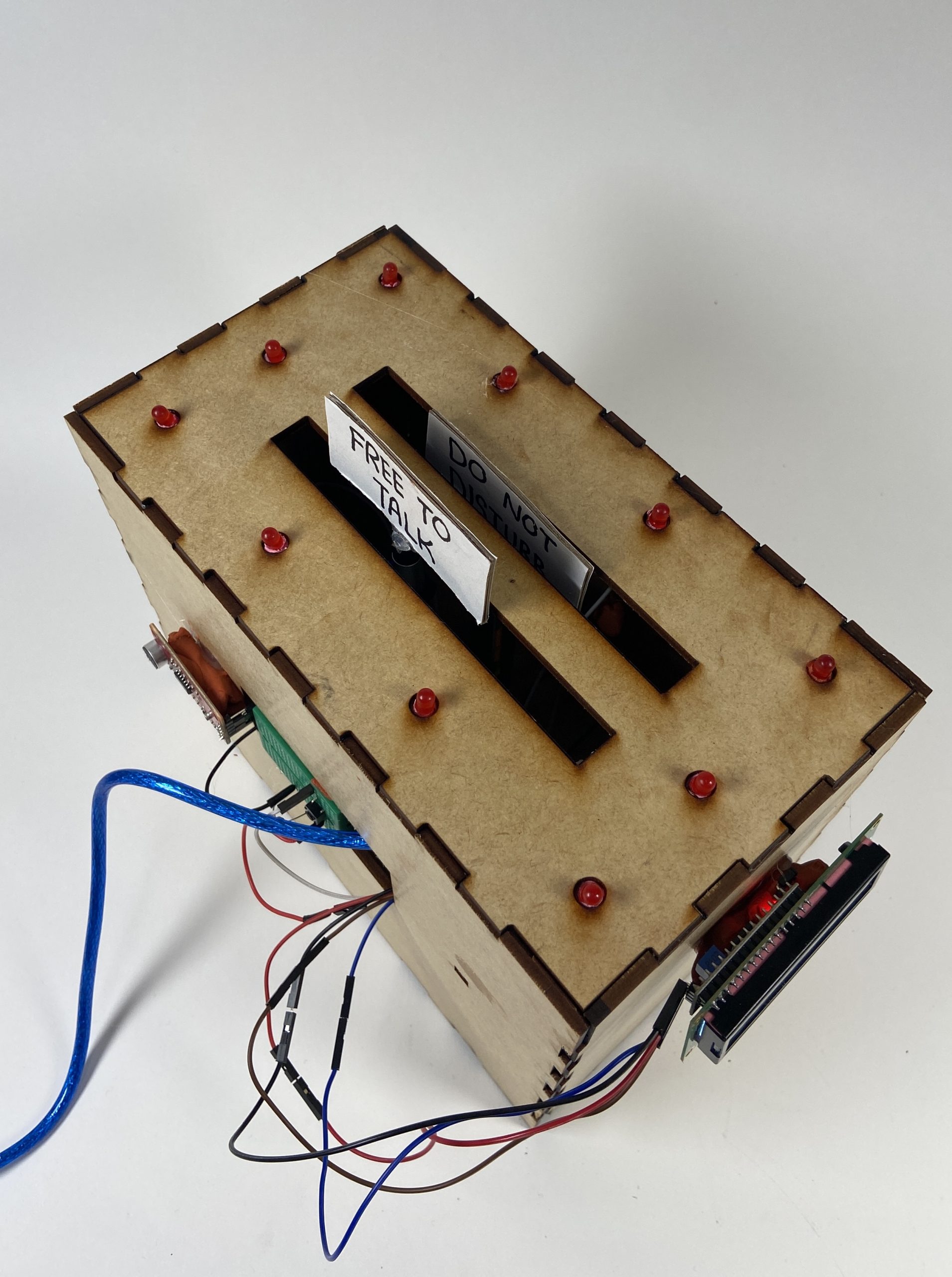
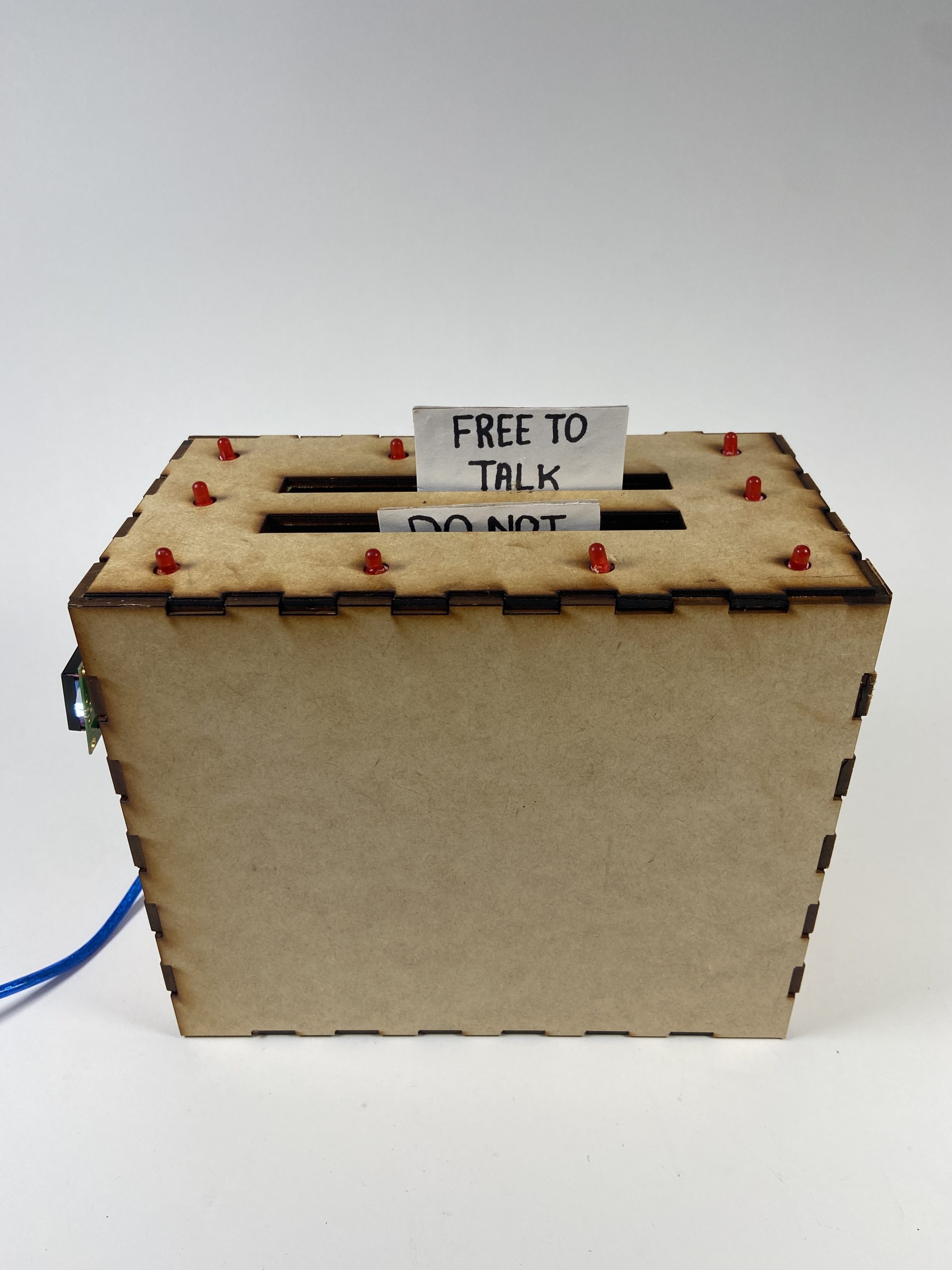
Detail Shot: This gives a good view of the top so you can see the whole top and all the LEDs. Also in this photo you can see the button, sound sensor, and the hole for all the cords, which is located on the back of the toaster. When the button is clicked it starts the Pomodoro timer.
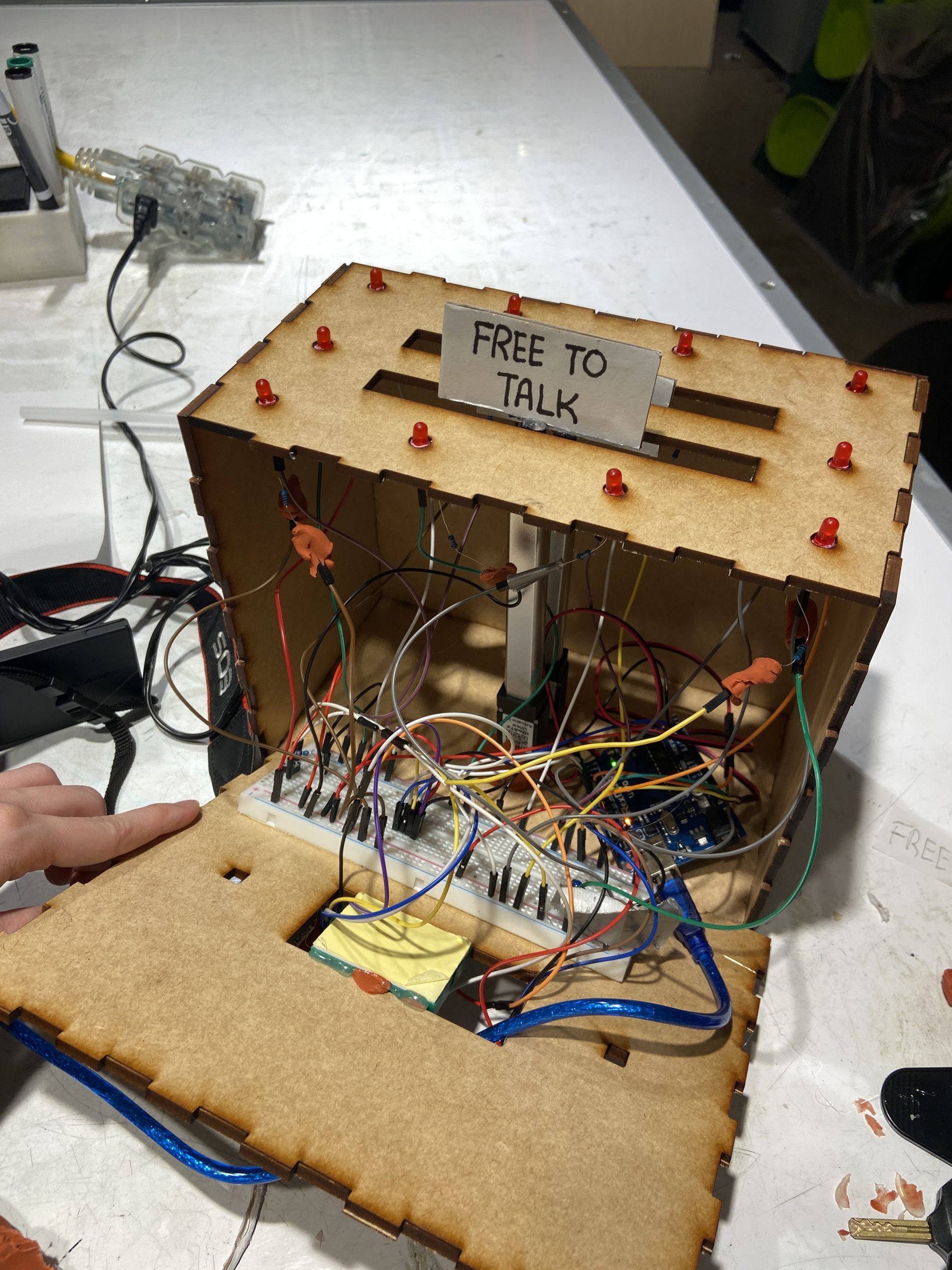
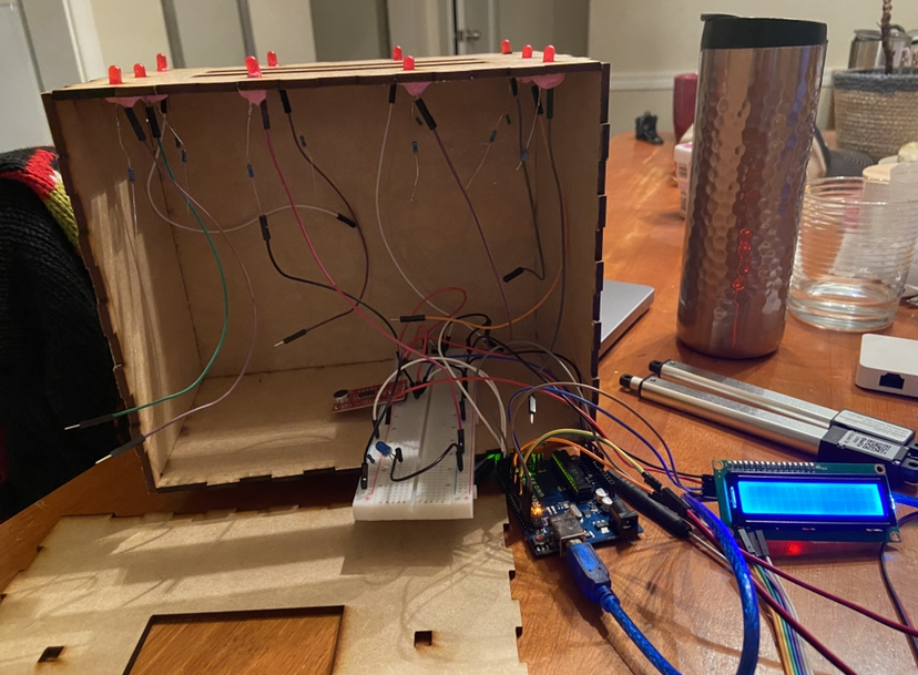
Detail Photo: This is the inside of the toaster. The wiring is pretty intense because of the 10 LEDs. I had to tape/puddy some connections so they wouldn’t come undone. I taped down/glued two bread boards inside so they stayed stable in the box to avoid loose connections, and so the switch would be available on the outside of the box.
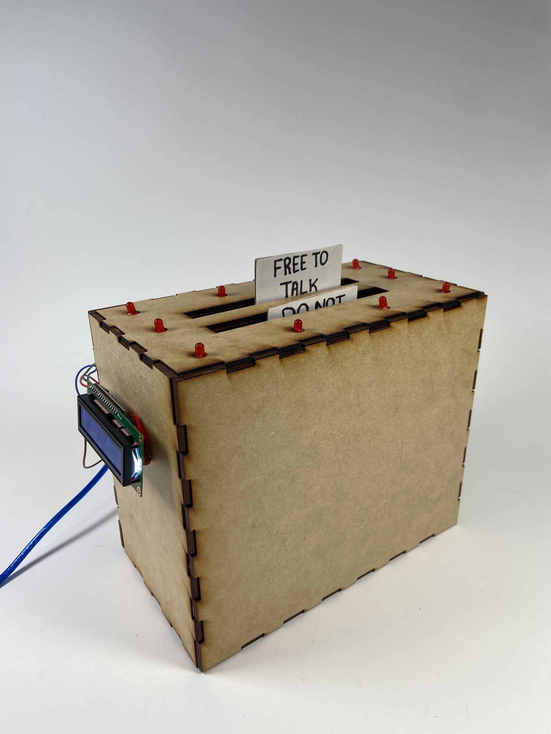
Action Photo: When the “Free To Talk” sign is up that means it is break time according to the Pomodoro timer. The timer will constantly switch between 25 minutes and 5 minutes because it is based off the Pomodoro technique for most efficient work. Work time is suppose to be 25 minutes long and break time is 5 minutes long.
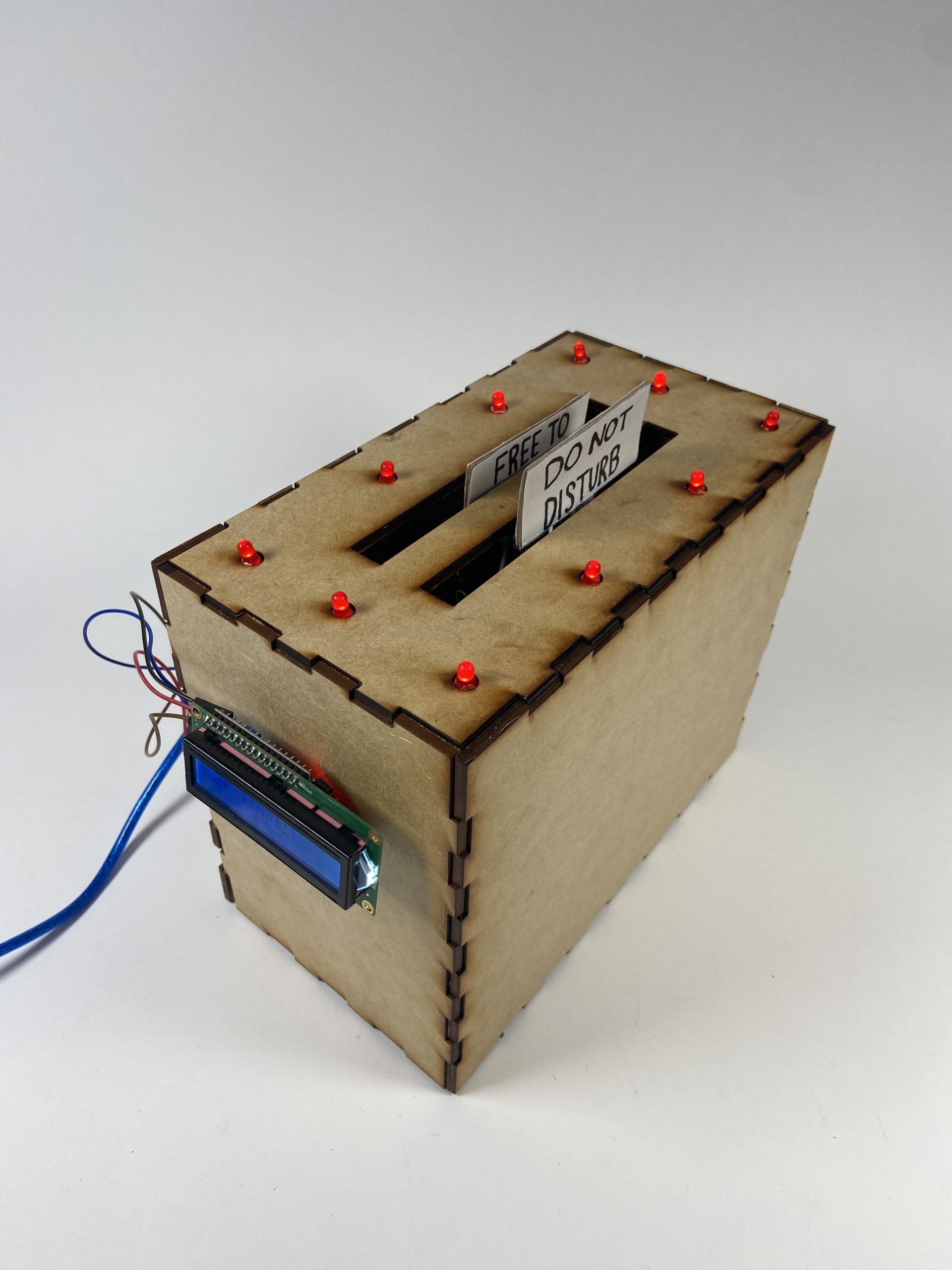
When the “Do Not Disturb” sign is up that means it is work time. The lights will flash if you start talking and if you talk loud enough they will blink red for 1 second to alert you that you are distracting the user from being productive. When the “Do Not Disturb” sign lowers then the toaster will stop flashing the LEDs.
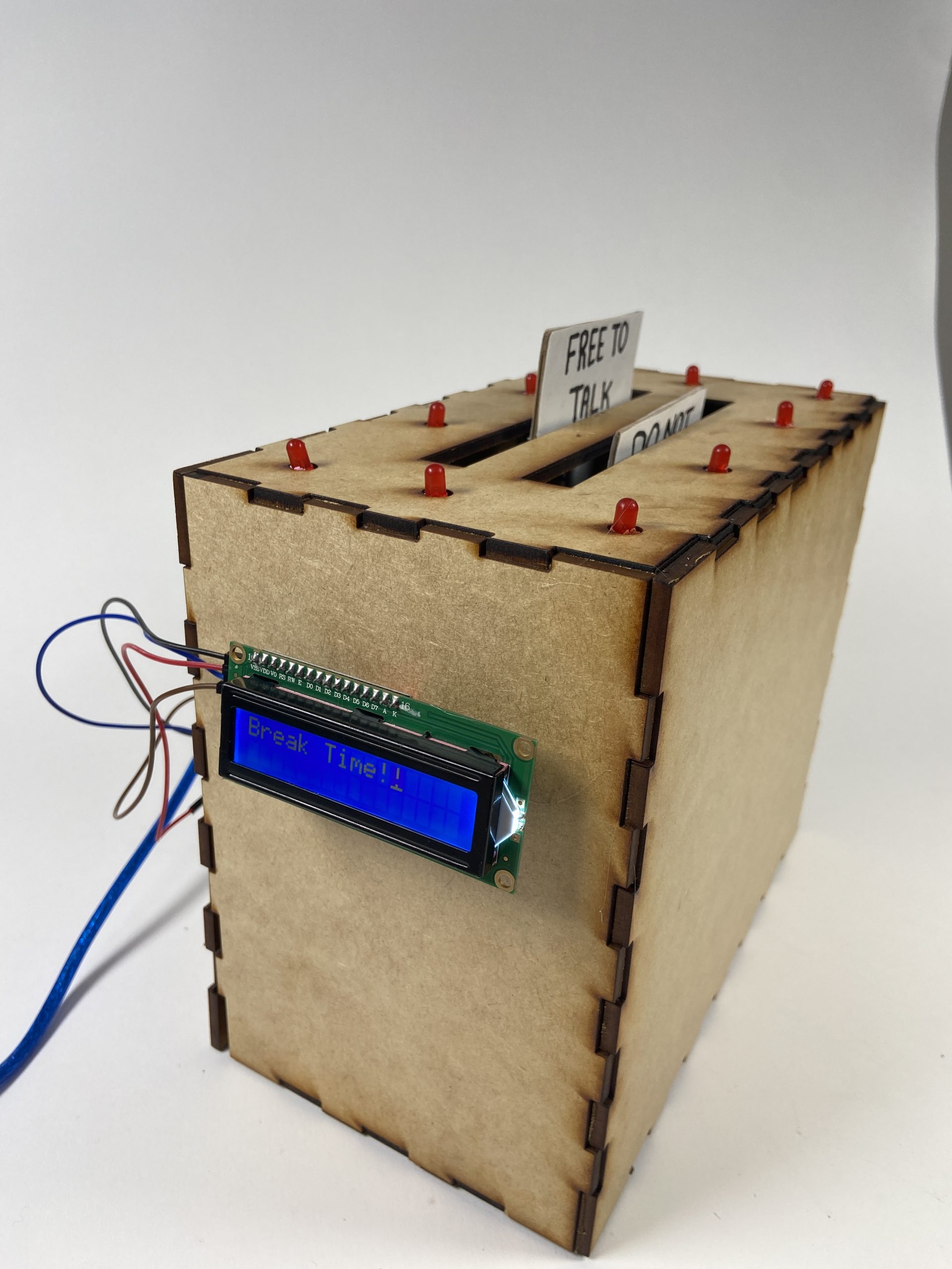
Action Photo: There is an LCD screen that is for the user to look at so they can know if it’s break time or work time. It is also there as another reminder to stay focused.
Action Photo: The sound sensor does not send signals to the lights when the “Free To Talk” sign is up. If there is minimal noise the lights will not light up. The toaster needs to detect “disturbing levels of noise” to flash lights. This makes it so the toaster can be used in a public area and notify people when they are being too disturbing so that the user doesn’t need to do it themselves.
Process
The first big decision in my process was deciding how the sound detector was going to identify it’s signals. I originally organized my sounds into quiet, moderate, and loud. After Zach helped me get a more reliable sound detection, I started messing with the sensitivity. I was adjusting what the Arduino identified as quiet and loud, and at this point I made the decision on what the toaster is going to react too. I decided that first of all there was going to be some wiggle room so that a loud room does not trigger the toaster. Then I made the decision that moderate and loud would have different response. I decided here that the toaster should get “more angry” when it detects loud noise, which would cause it to flash the red light longer. I think this thinking and decision making really effected the logic of my code and how I approached it. This decision came pretty earlier on and I think that is made obvious by how I coded the whole device. It overall had a heavy influence on the design.
The second big decision came much later in the process. When I was deciding how the toaster was going to look, I also considered how it was going to act and be interacted with. I made a couple last minute decisions when designing the outer look and experience. There were two things that I felt like were feeling unclear in my design. First, I was concerned it wouldn’t be obvious enough when the toaster would detect loud sounds. This made me realize I am going to need an LED strip or lots of LEDs. I decided that the design would look kinda pretty and less tacky if used little LEDs and had them dotted around the top, plus it would be hard to miss many LEDs flashing at you, especially 10. Secondly, I realize for some it may not be fully clear when it is break time or work time, so that is when I decided the LED screen was necessary, because it wasn’t always planned to be in the design. Thus, when I was designing the lasercut box I put in a rectangle hole for the LCD, however there was then an even more last minute switch up. Last minute I realized I made a switch for my box and that needs to be easily accessible on the outside. So, I ended up using the LCD hole as a place to put the breadboard with the switch in it so I didn’t have to open the box to start it. In the picture you can see the lasercut box before it’s fully assembled, and at this moment is when I realized I need to move the switch off my big breadboard and onto a tiny one.
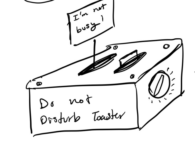
This is the first sketch of my device. What’s interesting is in the beginning of ideating I wasn’t thinking about the code as much, so in this drawing I have a knob that you can turn to the amount of time you want to work. I quickly realized after I moved out of ideating that this could be difficult and would potentially be a lot of coding, so I later opted for a button which is a simple on/off mechanism rather than the user being able to select a time.
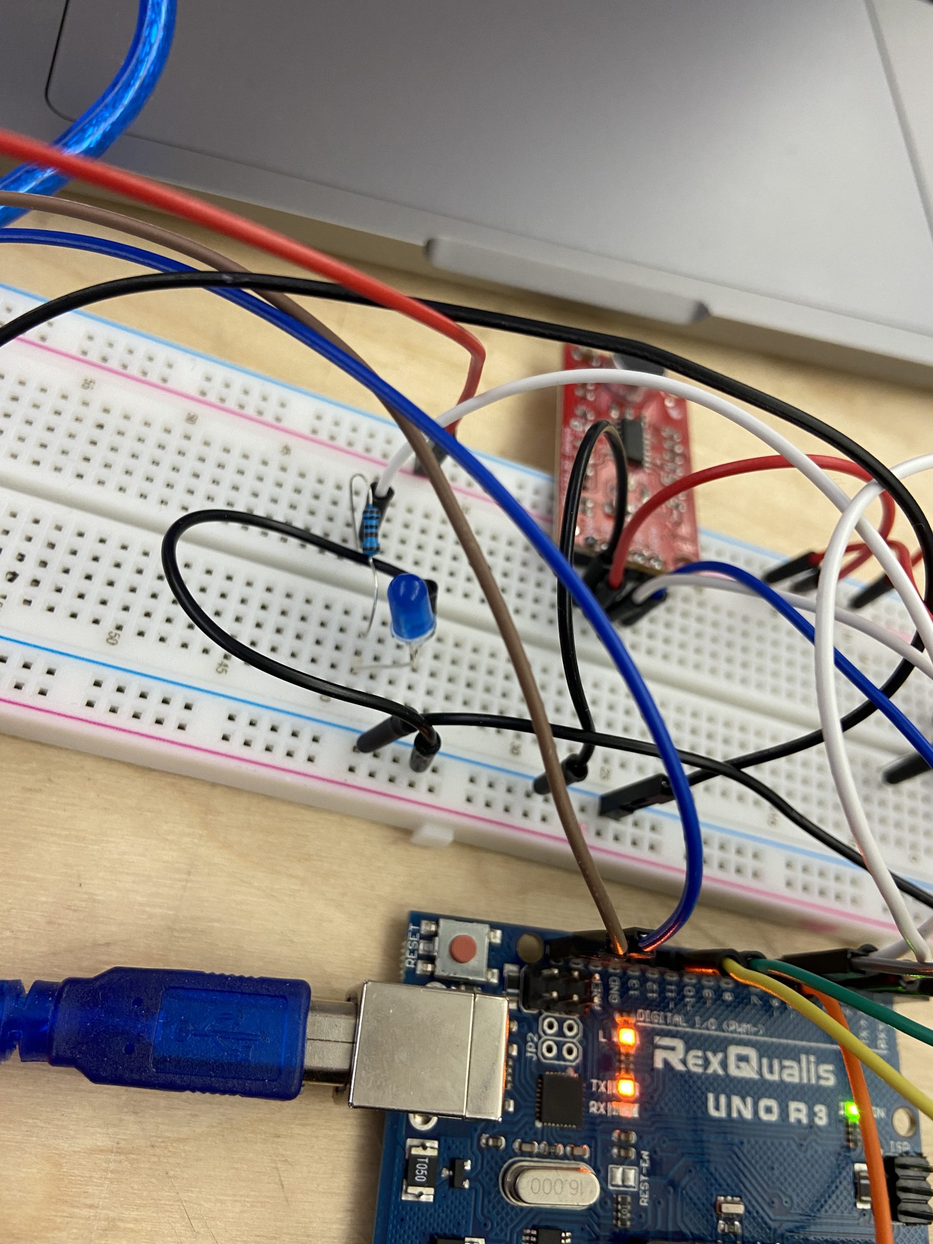
This is my setup to test the sound detector to light signal. So this helped me visualize how sensitive the sound detector is and also if the LED would actually light up when I wanted too. I did a lot of clap and talking and yelling with this simple set up when trying to calibrate my sensor properly.
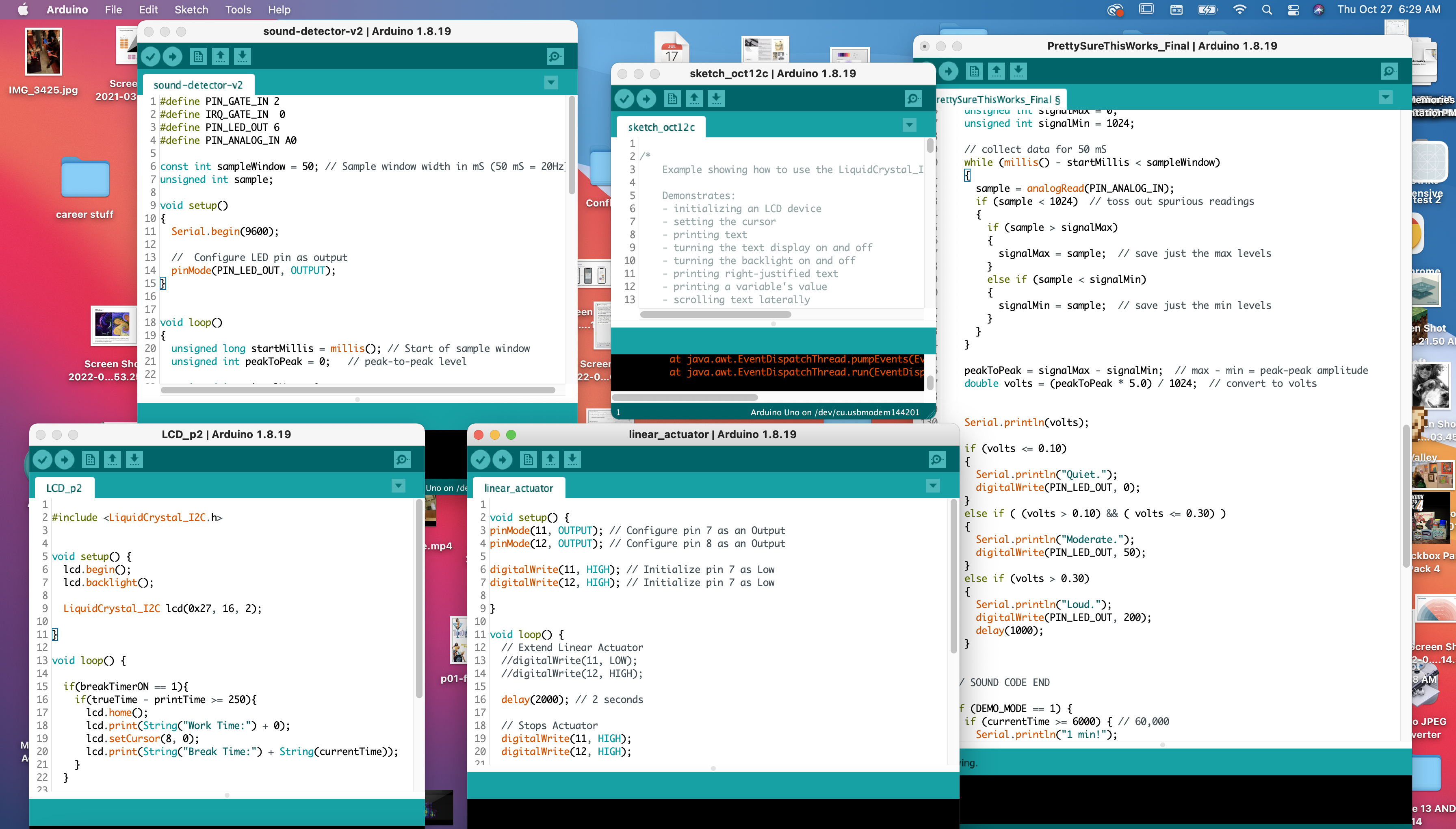
During the whole coding process I constantly had many Arduino files open. That is for a couple reasons. First reason is because I was looking at example code and trying new things out, so if I wanted to try a new approach I just made a new sketch and attempted in the new sketch (hence in this picture why I have two LCD sketches). Secondly, some sketch files were more for testing sensors or outputs. I had one sketch file that would reset the linear actuators for me. I also had a sketch file that would test the sound detector. I had another sketch file that would print the timer on the LCD screen for me. All of this helped me debug my code. Lastly, I was scared of messing up whatever I made work successfully, so I had each part of the system in it’s own sketch. Thus, I had an LCD sketch, Timer sketch, Sound Sensor + LED sketch, and a linear actuator sketch. So at the end of coding I had to compile all my sketches together carefully and neatly.
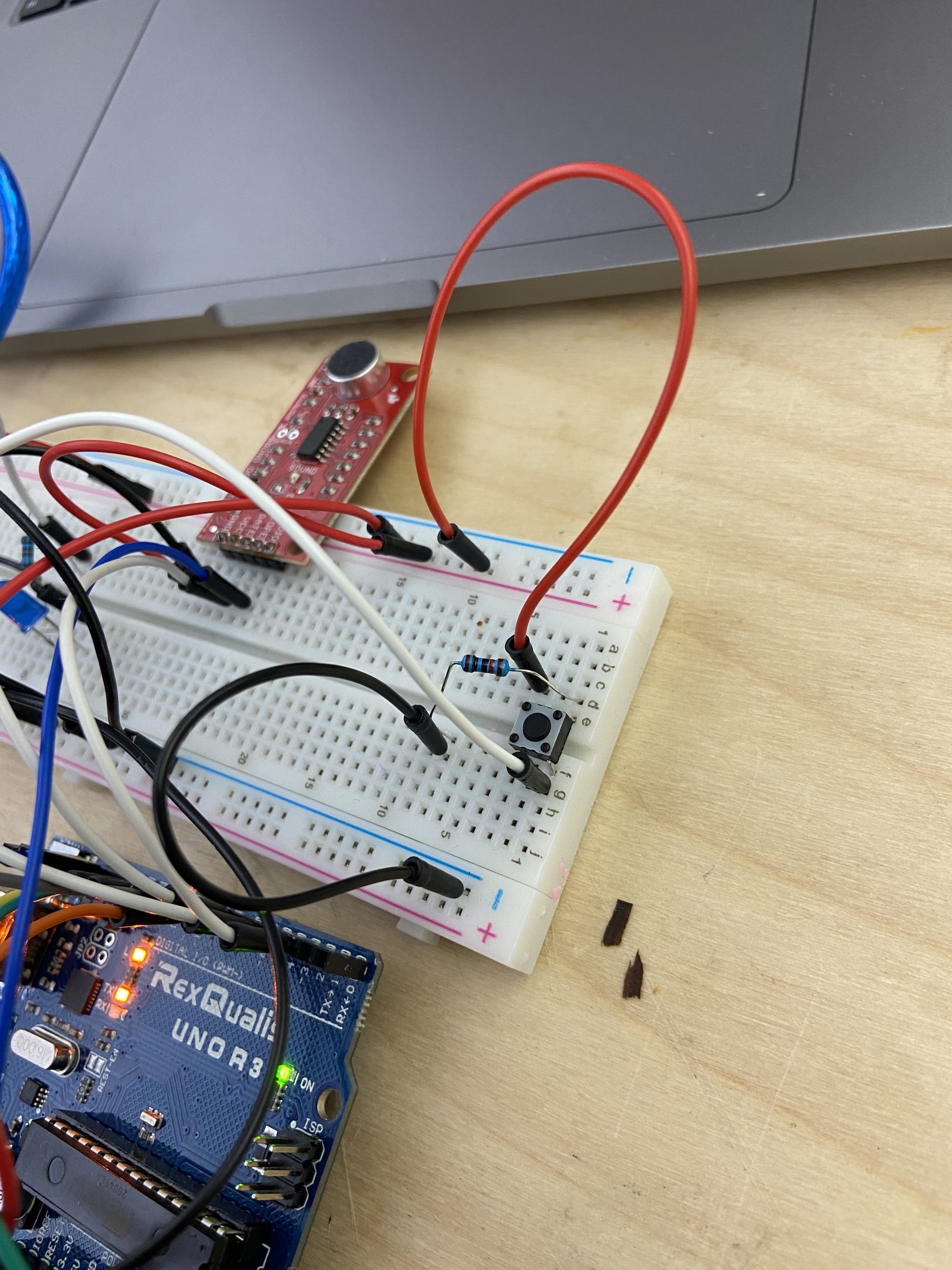
This is me wiring the button. I never wired a button before I had to kinda look it up and guess, but it ended up successfully and coded the button after wiring it.
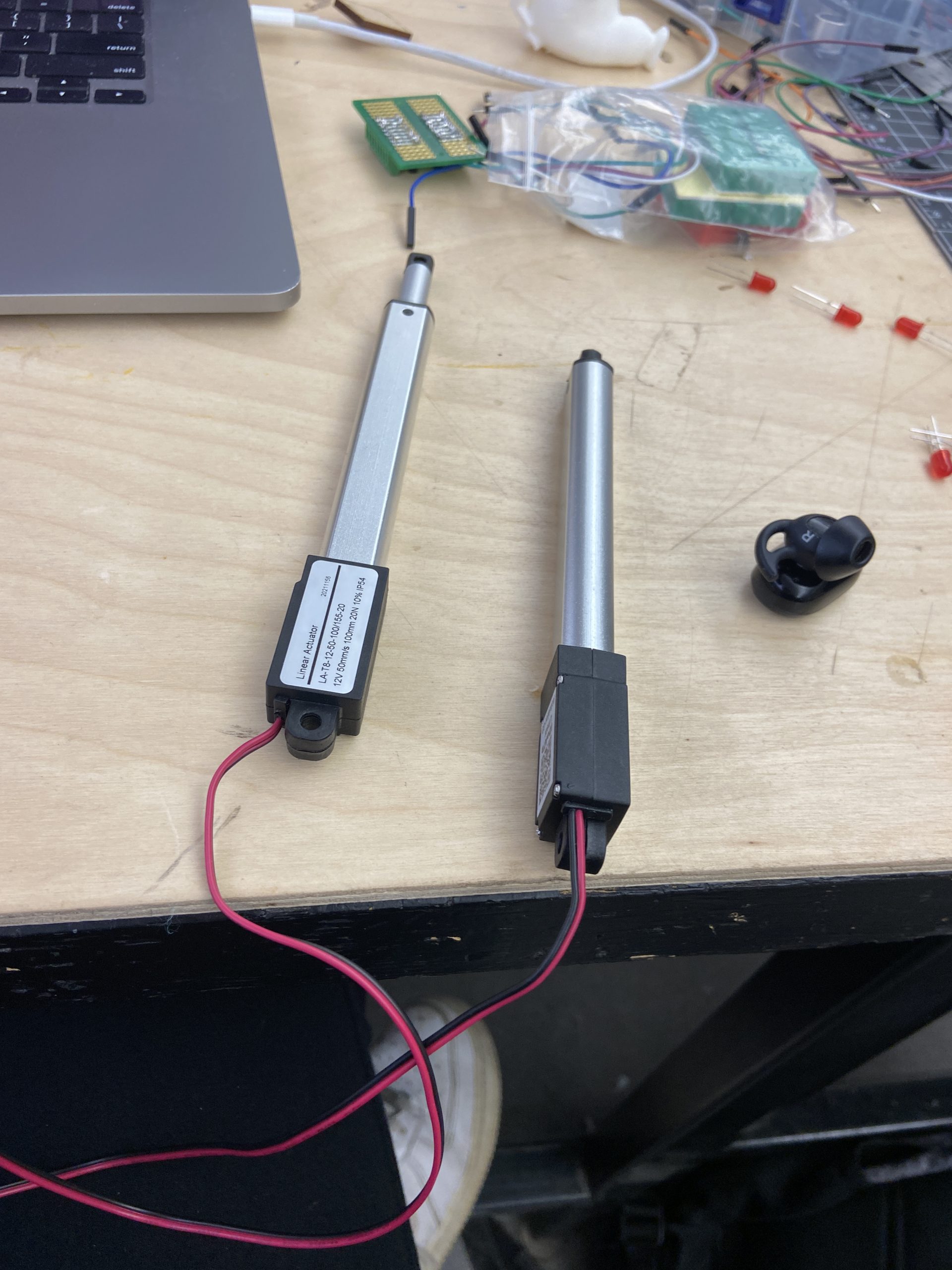
I had a lot of trouble with making the linear actuator fit into the code properly with my timer code I made. The main reason is because linear actuators aren’t told to go a distance, they are just told to go and stop. The example code I referenced used delays to make the linear actuator go the distance it wanted, so it was really difficult to fit that into code that was all based around millis(). It took a lot of experimenting with the linear actuators just sat on the table until I was able to figure out the code. It was also difficult because I have a break time mode and a work time mode in my code, so at first I had no idea where which linear actuator should be extended or retracted. That took a little bit of guessing and thinking through.
Discussion
I am overall pretty happy with my project. I think it does exactly what I intended it to do. It detects sound levels decently well and the linear actuators actually work perfectly how I intended them too. I think if anything I wish I could add in more of my fun ideas. For example, I wish I could add more stimuli to happen when the noise levels get loud. I think that would make the project even more fun and interesting. I also wish I did put more time into the design of the project just because I am a design major and I think it would enhance the interaction of this device.
Overall, I did fumble a lot along the way. I think I still don’t fully understand the sparkfun sound detector. I tried to calibrate it exactly how I wanted, but I only had so much time and I never got back around to it. Yet, the hardest part was actually making the timer and switching the modes between work and break. I am used to coding in functions, so for me, it is hard to code into a loop. A couple times I forgot that the program is constantly looping, which caused bugs. It took me a while to figure out ways around it (aka I made variables that acted as switches), but it was hard to figure out how to make my initial logic work. Then after that I had to add in the linear actuator code which was challenging because I couldn’t remember where break mode and work mode was being turned off and on. So, I think overall, my code could’ve been much cleaner because it started to confuse me. I think there’s too many switches on and off and there must be a way to simplify and make the variable names clearer.
The critiques brought up some great points and I actually ended up listening to one of them. The first one that stood out said “Maybe add double sided signs and have the signs disappear all the way into the toaster”. I strongly agreed with them and I ended up remaking my signs to be double sided and sturdier, however, the linear actuators are too tall to actually get the signs all the way in, but I would’ve loved to also incorporate that into my design. The second critique said “I would say if, theoretically, you were trying to use this device in a library, or somewhere quiet, then the sound of the linear actuators might be a bit loud and counterintuitive for its purpose”. I honestly don’t have a solution for that currently, but I thought this was an interesting thing to point out. I kinda agree that the sound could end up being distracting, yet my limitations were partially due to what was available.
If I were to make a whole new iteration, I would definitely clean up the wiring and code, since those both caused me lots of extra time. However, I also think there’s so many ways to expand on this idea like adding a more advanced timer, or adding more interactions that help keep you on task, thus I think this would be a really good project to iterate on because of the endless possibilities.
Technical Information

/* The Do Not Disturb Toaster
  By: Gia Marino

  My code has a switch that tells when the program should start.
  Then the program takes a start time and starts calculating time passed.
  If currentTime hits 25 mins and the program is not in break mode
  then it will switch over to break mode and move the linear actuator to
  indicate this. If it is in break mode and the currentTime hits 5 minutes
  then the program will switch into break mode and moves linear actuator
  accordingly. If in workmode the program will take inputs from the sound
  detector and send signals to the LED pin if detects moderate or loud noise.
  It continuously switches inbetween these modes unless stopped.


  Arduino pin | role   | description
  ------------|--------|-------------
  A0            input    enevelope pin on sound detector
  2             output   gate pin on sound detector
  6             output   LED pin
  4             input    button pin
  7             output   DO NOT Disturb linear actuator
  8             output   DO NOT Disturb linear actuator
  11            output   FREE to talk linear actuator
  12            output   FREE to talk linear actuator
  SDA           output   LCD serial pin
  SCL           input    LCD clock pin
  GND           input    ground
  5V            output   5v

  My linear actuator code was inspired by
  https://www.firgelliauto.com/blogs/tutorials/how-do-you-control-a-linear-actuator-with-an-arduino.
  I used this code to start and ended up breaking it up into two parts and putting that into my if
  statements. Secondly, my sound detector code was copied from
  https://learn.adafruit.com/adafruit-microphone-amplifier-breakout/measuring-sound-levels. I basically
  left most of it the same since it worked well for my application and I labeled it as the sound detector code.
  Additionally, I used https://learn.sparkfun.com/tutorials/sound-detector-hookup-guide/all#software-example
  as a launchpad to creating my sound detector code. I ended up not following it for my main code, but my code
  may be slightly inspired by this source. To understand button wiring and coding, I referenced https://youtu.be/TIBa_RQB3Ek.
  Lastly, we copied the LCD tutorial code and worked off of that, so our code for the LCD display
  is also heavily influenced by this tutorial: https://courses.ideate.cmu.edu/60-223/f2022/tutorials/I2C-lcd
*/


//LCD set up
#include <Wire.h>
#include <LiquidCrystal_I2C.h>
LiquidCrystal_I2C screen(0x27, 16, 2);

#define BUTTON_PIN 4    //button pin
#define PIN_GATE_IN 2   //sound detector
#define PIN_LED_OUT 6   // all LEDs are hooked up to pin 6
#define PIN_ANALOG_IN A0    //sound detector

// sound detector variables
const int sampleWindow = 50; // Sample window width in mS (50 mS = 20Hz)
unsigned int sample;

bool workTimerSwitch; //tells the program it is work mode
bool breakTimerSwitch;  //tells the program it is break mode
//this tells program whether it is break time mode (when 1) or work time mode (when 0)
bool breakTimerON;

unsigned long startTime; // when the timer starts
unsigned long currentTime = 0; // how long the timer has been going

bool DEMO_MODE = 1; // Demo mode is turned on if 1
bool startToaster = 0;  // variable that indicates that button turned on toaster
bool TURN_MIC_ON = 0; // lets the program know whether the LEDs should flash if theres sound


void setup() {

  Serial.begin(9600);
  pinMode(BUTTON_PIN, INPUT);
  pinMode(PIN_LED_OUT, OUTPUT);

  //LCD
  // initialize the screen (only need to do this once)
  screen.init();
  // turn on the backlight to start
  screen.backlight();
  screen.clear();

  //break time actuator
  pinMode(7, OUTPUT); // Configure pin 7 as an Output
  pinMode(8, OUTPUT); // Configure pin 8 as an Output

  digitalWrite(7, HIGH); // Initialize pin 7 as Low
  digitalWrite(8, HIGH); // Initialize pin 7 as Low

  //work time actuator
  pinMode(11, OUTPUT); // Configure pin 11 as an Output
  pinMode(12, OUTPUT); // Configure pin 12 as an Output

  digitalWrite(11, HIGH); // Initialize pin 11 as Low
  digitalWrite(12, HIGH); // Initialize pin 12 as Low


}

void loop() {

  unsigned long globalTime = millis(); // the global time

  //this variable stores whether button was pressed
  int ON = digitalRead(BUTTON_PIN);

  // if button is pressed then this if statement swtiches the startToaster
  //variable on HIGH which will start the program
  if (ON == 1) {
    startToaster = 1;
  }

  if (startToaster == 1) {
    currentTime = globalTime - startTime; // calculates currentTime
  }

  if (currentTime >= 1500000) { // work timer reached 25 mins
    Serial.println("25 mins!");

    // Retracts Linear Actuator
    digitalWrite(11, HIGH);
    digitalWrite(12, LOW);
    delay(2000); // 2 seconds
    // Stop Actuator
    digitalWrite(11, HIGH);
    digitalWrite(12, HIGH);

    // extends breaktime linear actuator
    digitalWrite(7, LOW);
    digitalWrite(8, HIGH);
    delay(2000); // 2 seconds
    digitalWrite(7, HIGH);
    digitalWrite(8, HIGH);

    // it is break mode so sound does not need to activate LED
    TURN_MIC_ON = 0;

    //LCD
    screen.home();
    screen.print(String ("Break Time!"));

    startTime = globalTime; // reset
    breakTimerSwitch = 1; // turns on break time mode
  }

  // this is so the program doesn't continue to loop in the workTimer statment
  // b/c otherwise it would continue to reset startTime which would make currentTime zero
  // hence why the variable is labeled as a switch
  if (workTimerSwitch == 1) {
    startTime = globalTime;
    workTimerSwitch = 0;
  }

  if (breakTimerSwitch == 1) { // break timer switched on
    breakTimerON = 1;
    startTime = globalTime; // reset
    breakTimerSwitch = 0; // switch is turned off so program doesn't loop in statement
  }

  if (breakTimerON == 1) {
    if (currentTime >= 300000) { // 5 mins
      Serial.println("5 mins!");

      // Retracts break time Linear Actuator
      digitalWrite(7, HIGH);
      digitalWrite(8, LOW);
      delay(2000); // 2 seconds

      // Stop Actuator
      digitalWrite(7, HIGH);
      digitalWrite(8, HIGH);

      // Extend Linear Actuator
      digitalWrite(11, LOW);
      digitalWrite(12, HIGH);

      delay(2000); // 2 seconds

      // Stops Actuator
      digitalWrite(11, HIGH);
      digitalWrite(12, HIGH);

      // sound detection should now activate LEDs since in work mode
      TURN_MIC_ON = 1;

      // LCD
      screen.home();
      screen.print(String ("Work Time!"));

      startTime = globalTime; // reset
      breakTimerON = 0; // will make program exit this if statement
      workTimerSwitch = 1; // switch into work mode
    }
  }

  // SOUND DETECTOR CODE
  if (TURN_MIC_ON == 1) {
    unsigned long startMillis = millis(); // Start of sample window
    unsigned int peakToPeak = 0;   // peak-to-peak level
    unsigned int signalMax = 0;
    unsigned int signalMin = 1024;

    // collect data for 50 mS
    while (millis() - startMillis < sampleWindow)
    {
      sample = analogRead(PIN_ANALOG_IN);
      if (sample < 1024)  // toss out spurious readings
      {
        if (sample > signalMax)
        {
          signalMax = sample;  // save just the max levels
        }
        else if (sample < signalMin)
        {
          signalMin = sample;  // save just the min levels
        }
      }
    }

    peakToPeak = signalMax - signalMin;  // max - min = peak-peak amplitude
    double volts = (peakToPeak * 5.0) / 1024;  // convert to volts

    if (volts <= 0.10) // quiet noise levels
    {
      Serial.println("Quiet.");
      digitalWrite(PIN_LED_OUT, 0);
    }
    else if ( (volts > 0.10) && ( volts <= 0.30) )
    {
      Serial.println("Moderate.");    // moderate noise levels
      digitalWrite(PIN_LED_OUT, 50);
    }
    else if (volts > 0.30)
    {
      Serial.println("Loud.");     // loud noise levels
      digitalWrite(PIN_LED_OUT, 200);
    }
  }

  // DEMO MODE

  if (DEMO_MODE == 1) { // DEMO MODE is turned on
    if (currentTime >= 6000) { // 1 min

      // Retracts Linear Actuator
      digitalWrite(11, HIGH);
      digitalWrite(12, LOW);
      delay(2000); // 2 seconds
      // Stop Actuator
      digitalWrite(11, HIGH);
      digitalWrite(12, HIGH);

      // extends breaktime linear actuator
      digitalWrite(7, LOW);
      digitalWrite(8, HIGH);
      delay(2000); // 2 seconds
      digitalWrite(7, HIGH);
      digitalWrite(8, HIGH);

      // it is break mode so sound does not need to activate LED
      TURN_MIC_ON = 0;

      //LCD
      screen.home();
      screen.print(String ("Break Time!"));

      startTime = globalTime; // reset
      breakTimerSwitch = 1; // turns on break time mode
    }
    if (breakTimerON == 1) {
      if (currentTime >= 6000) { // 1 min

        // Retracts break time Linear Actuator
        digitalWrite(7, HIGH);
        digitalWrite(8, LOW);
        delay(2000); // 2 seconds

        // Stop Actuator
        digitalWrite(7, HIGH);
        digitalWrite(8, HIGH);

        // Extend Linear Actuator
        digitalWrite(11, LOW);
        digitalWrite(12, HIGH);

        delay(2000); // 2 seconds

        // Stops Actuator
        digitalWrite(11, HIGH);
        digitalWrite(12, HIGH);

        // sound detection should now activate LEDs since in work mode
        TURN_MIC_ON = 1;

        // LCD
        screen.home();
        screen.print(String ("Work Time!"));

        startTime = globalTime; // reset
        breakTimerON = 0; // will make program exit this if statement
        workTimerSwitch = 1; // switch into work mode
      }
    }
  }
}