This device is designed to be placed on a bike, and signal to other vehicles with its lighting.
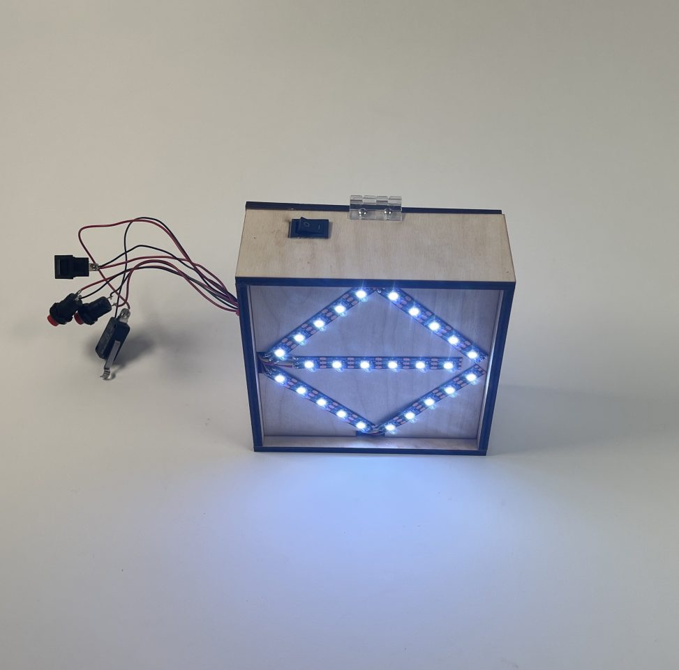
Overall Picture with Reference
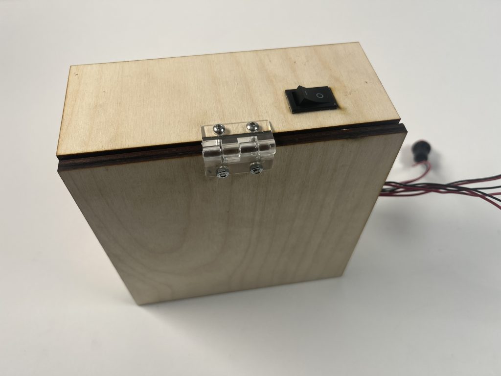
Back View of the Device
Video of it Working:
This video is taken in the dark to show its real-world effect as such a device is most crucial during nighttime.
Process & Decisions:
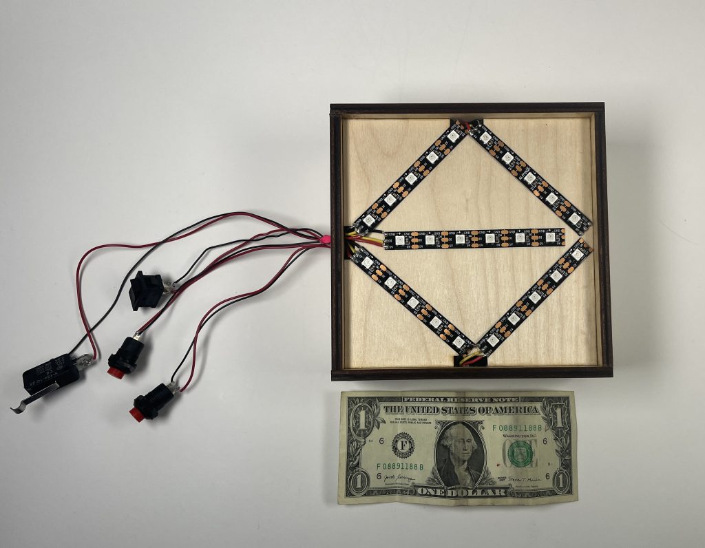
The first major decision I made is to utilize multiple small pieces of LED strip and orientate them in a specific way to show a signal for left turn, right turn, and breaking. In my initial design, I have a circle as part of my stop signal. However, bending LED strips isn’t really a choice, and the only solution to that is to place the LEDs perpendicular to the surface of the device, which then makes them very hard to mount as those LED strips already have tapes applied on the back. The final decision on this is to remove the circular shape LED strip and have a rectangular-shaped stop sign instead, which still looks very good as shown in the video above.

Planned Layout In The Initial Design
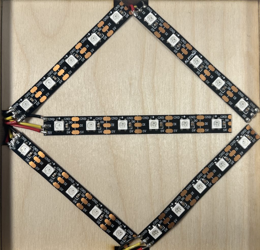
LED Strips Layout on the Device
The second decision is about powering the whole system. LED strips take quite a bit of power, so I decided to use a battery pack with 4 rechargeable AA batteries to power both the Arduino, the LED strips, and all four switches. To organize all the power lines and prevent any possible shorts, I used a small circuit board to sort out all the wires. In addition, I added a small power switch that is embedded in the top wall of the case to control the power of the device.
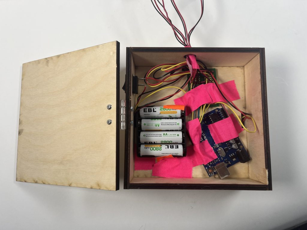
An Overview of the Inside
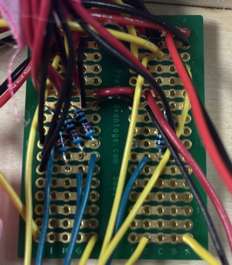
Main Circuit Board
Another decision I made are the inputs. The left turn and right turn inputs are non-toggled regular buttons, which I believe to be most convenient in actual usage as they are intended to be placed rider’s two thumbs on the handlebar. Needless to say, the night light switch is a toggled switch and the break switch is a hinge lever switch that will be placed between the break bar and the handlebar, so whenever the rider breaks, the lever switch gets pressed and actuates as well.
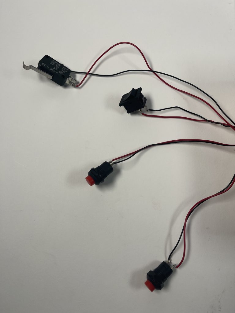
Switches From Top to Bottom: Break, Night Light, Left Turn, Right Turn
Discussion
One major criticism of this device is the night light color. Conventionally, white lights are located at the front of a vehicle, so having a night light being white and placed at the rear of the bike may very likely confuse the person behind especially in the dark. However, since those LED strips are programmable in terms of their colors, I could easily change the color for a night light, which could be a potential solution. Another criticism is the case of the device. Being weatherproof is a crucial part of any device that is intended to be used outside, and this one is no exception. Yet the wooden case isn’t the best choice in terms of weatherproofing.
Such an issue leads to my view of this project. I consider this device still at a development stage, as it is not ready to be brought outside and use in the real world. My original intention is to mount this device to the back of my bike, but that goal is still quite far as the mounting brackets are still to be made. Overall, I think I have achieved everything I want for this device to work in a lab, but further development is needed for it to be actually useful.
Though I may not be all that satisfied with the device itself, what I was satisfied with are the things that I learned and experienced throughout this project. Things that I have never heard of like potting and experiences using the laser cutter for the wooden casing. I also learned from other people who utilized acrylic for their projects as that would be a better material for me to use instead of plywood as it is at least waterproof if sealed properly and allow for a clear view of the inside for presentations. After all, the biggest lesson that this project has given me is to think ahead to real-world applications and challenges when designing.
It is on my schedule to make further improvements to this project, namely using the smaller Arduino micro or nano and going through the process of potting for a more secure and waterproof case. As for the buttons, I will look into some waterproofed switches and buttons and ways to mount them onto a bike.
Technical Information

Functional Block Diagram

Electrical Schematic
/* Light Signal For Bike

    The following code is intended to lights up a set of LED strips according to the 4 inputs.
    When Left Turn is on, Upper Left, Lower Left, and Middle LED Strip turn "on", which is red
    When Right Turn is on, Upper Right, Lower Right, and Middle LED Strip turn "on", which is red
    When Break is on, All 5 LED strips turn "on", which is red
    When Night Light is on, All 5 LED strips turn "night", which is white
    Night Light has the lowest priority while other three action has equal priority.
    Pin Mapping:
    Arduino Pin  /  Role / Description
      2            Output   Upper Left LED Strip
      3            Output   Middle LED Strip
      4            Output   Upper Right LED Strip
      5            Output   Lower Right LED Strip
      6            Output   Lower Left LED Strip
      7            Input    Left Turn Signal
      8            Input    Right Turn Signal
      9            Input    Break Signal
      10           Input    Night Light Signal

      Ethan Hu, 2022
*/

#include <PololuLedStrip.h>
// setup PololuLedStrip and set each strip to a pin number
PololuLedStrip<2> ledStripLU;
PololuLedStrip<6> ledStripLD;
PololuLedStrip<4> ledStripRU;
PololuLedStrip<5> ledStripRD;
PololuLedStrip<3> ledStripM;
// defind the number of LED on each strip, the maximum LED count used in this project is 6
#define LED_COUNT 6
// define the input pin number for the four switches
#define Left_Input 7
#define Right_Input 8
#define Nightlight_Input 10
#define Break_Input 9
// create lists of colors for the LED strips to show under different circumstances
rgb_color on[LED_COUNT];
rgb_color off[LED_COUNT];
rgb_color night[LED_COUNT];

void setup() {
  pinMode(Left_Input, INPUT);
  pinMode(Right_Input, INPUT);
  pinMode(Nightlight_Input, INPUT);
  pinMode(Break_Input, INPUT);
  // set up the list of color
  for (int i = 0; i < LED_COUNT; i++) {
    // on is red
    on[i] = rgb_color(255, 0, 0);
  }
  for (int i = 0; i < LED_COUNT; i++) {
    // off is clear/nothing
    off[i] = rgb_color(0, 0, 0);
  }
  for (int i = 0; i < LED_COUNT; i++) {
    // night is white
    night[i] = rgb_color(255, 255, 255);
  }
}

void loop() {
  // if left turn
  if (digitalRead(Left_Input) == HIGH) {
    ledStripLU.write(on, LED_COUNT);
    ledStripLD.write(on, LED_COUNT);
    ledStripRU.write(off, LED_COUNT);
    ledStripRD.write(off, LED_COUNT);
    ledStripM.write(on, LED_COUNT);
  }
  // if right turn
  else if (digitalRead(Right_Input) == HIGH) {
    ledStripRU.write(on, LED_COUNT);
    ledStripRD.write(on, LED_COUNT);
    ledStripLU.write(off, LED_COUNT);
    ledStripLD.write(off, LED_COUNT);
    ledStripM.write(on, LED_COUNT);
  }
  // if break
  else if (digitalRead(Break_Input) == LOW) {
    ledStripRU.write(on, LED_COUNT);
    ledStripRD.write(on, LED_COUNT);
    ledStripLU.write(on, LED_COUNT);
    ledStripLD.write(on, LED_COUNT);
    ledStripM.write(on, LED_COUNT);
  }
  // the second else is used to check whether if night light is toggled
  else {
    // if night light is toggled on
    if (digitalRead(Nightlight_Input) == HIGH) {
      ledStripRU.write(night, LED_COUNT);
      ledStripRD.write(night, LED_COUNT);
      ledStripLU.write(night, LED_COUNT);
      ledStripLD.write(night, LED_COUNT);
      ledStripM.write(night, LED_COUNT);
    }
    // all the LED will turn off if no signal is sent to it and night light is not toggled on
    else {
      ledStripRU.write(off, LED_COUNT);
      ledStripRD.write(off, LED_COUNT);
      ledStripLU.write(off, LED_COUNT);
      ledStripLD.write(off, LED_COUNT);
      ledStripM.write(off, LED_COUNT);
    }
  }
}