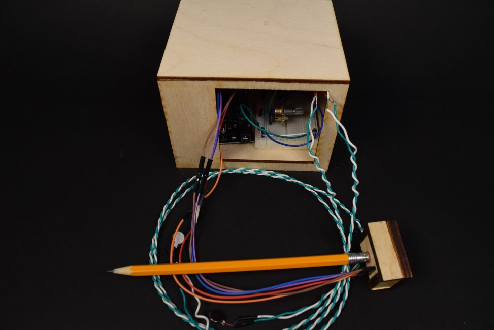
The Waker-Upper is an assistive device that prevents students from falling asleep in class by sending vibrations when they stop writing or moving the pencil for at least five seconds.
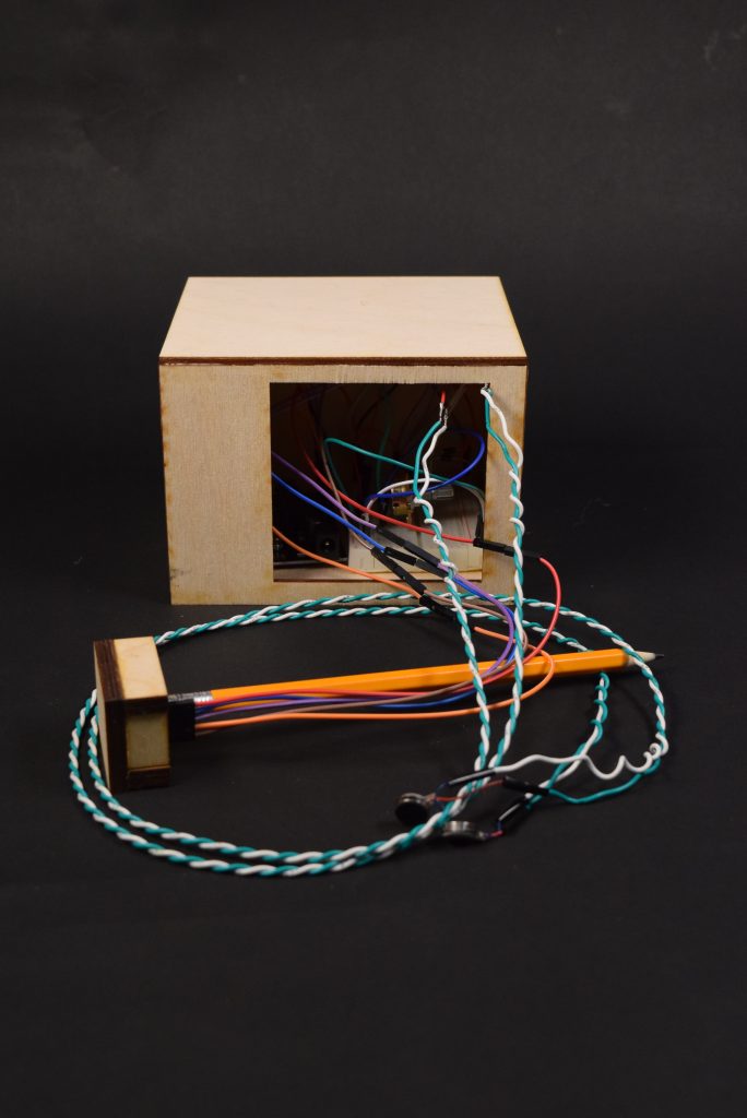
Overall view of The Waker-Upper

Close up to potentiometer
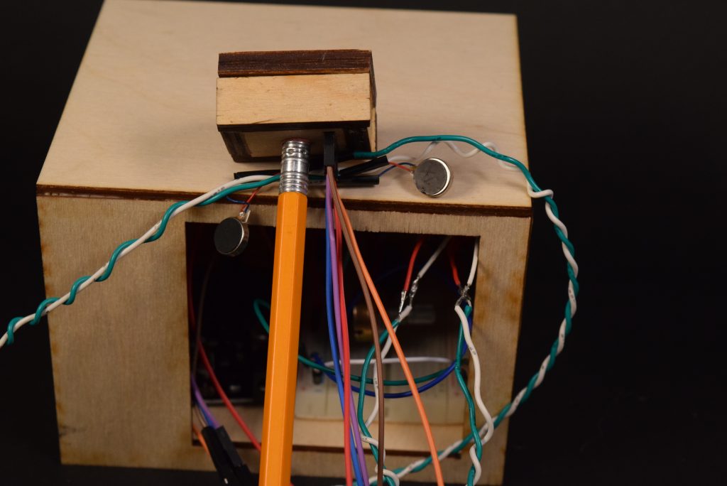
Close up view of pencil and vibrating motors
See video of it in action here
Process
- The first major decision point I made was in the idea creation. My original idea was to have a speaker wake up the student when he/she fell asleep instead of the vibrating motor. However, I realized that this idea was implausible as it would be distracting to the people around me when using it; therefore, I had to think of new ideas to wake you up that wouldn’t be irritating to those around you. Eventually, I settled upon the vibrating motor after testing it out and seeing how quiet it was.
- Another major decision point was how to account for the noise and change in x, y, and z motion that occurred when the pencil was stationary. At first, I arbitrarily decided a number and used testing to determine if it worked. However, this way was inefficient and made the value difficult to adjust since you would need to change it directly in the code and re-upload it to the Arduino. Therefore, I decided to use a potentiometer, so the user could directly change the value without having to edit the code. Using the potentiometer also made it easier to determine the value that worked best.

Original test for noise
In order to create this project, there was a lot of testing involved due to the variability of the accelerometer and noise in the room. The first image is the original test I used to check for noise. I taped a small breadboard on top of the pencil to test the range of change in the x, y, and z direction when you’re writing versus leaving the pencil stationary. Eventually, I realized this approach was too difficult, so I switched to the potentiometer approach I described above.
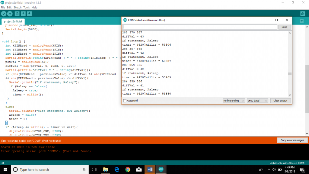
Using serial feedback to debug code
This image illustrates my debugging process. I used serial feedbacks to determine the problems with my code. The first line is the X, Y, and Z values of motion the accelerometer picked up and the second line is the diffVal, which is set by the potentiometer and is adjusted to account for the noise. This value allows for the user to easily adjust for noise without having to edit the code. The third line is used to determine which part of the code you’re in to see if the vibrating motors are functioning correctly. For example, during testing, I wanted to determine if the vibrating motors weren’t turning on because of a wiring issue or a logic issue in the code and this feedback line helped me figure it out. The fourth line is the millis and timer values, which was used to determine if the timing was working correctly.
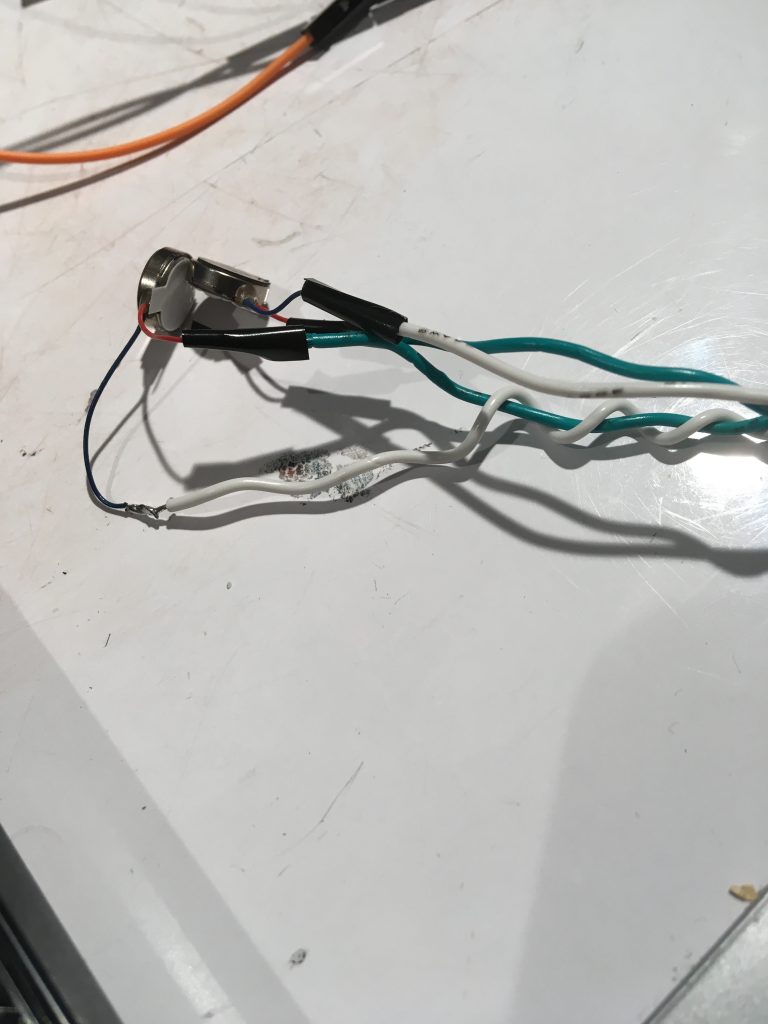
Makeshift solution using electrical tape to keep vibrating motor attached to wire
In order to attach the vibrating motors to the wires, I needed to solder it. However, since the wire of the motors was thin and the motors vibrated, the attachment kept becoming undone. After re-soldering multiple times and knowing we were out of heat shrink, I used electrical tape to keep them better protected.

Completed circuit
Disscussion
- Self-critique: Overall, I am satisfied with how my project came out. It works as it was intended to and will succeed in waking you up if you fall asleep in class. I can see myself using this in certain classes and even making a new one for my friend. My only dissatisfaction was with the appearance of my project. The box with the breadboard and Arduino is a little too big to be able to store in a classroom setting. Also, the wires coming out of the pencil make using it in class not ideal. In the end, I’m proud of myself for being able to bring my idea to fruition and for succeeding in making a working project.
- Surprises : The creation of my project didn’t have too many surprises. The biggest surprise for me was how often the motors I soldered fell off. I must have soldered each motor at least five times. I was also surprised by how much harder it is to do a project alone rather than with a partner. To finish alone, you really need to understand everything and figure things out yourself rather than relying on your partner.
- What I learned: I learned a lot in this project. I learned how to solder and strip wires, which I have never done before. The project also helped me become more proficient in the use of millis for timing and setting up Boolean variables, which I somewhat understood thanks to the homework questions. Furthermore, the project taught me the importance of using serial feedback to debug as that was what I spent the most time doing. I also learned about the map function and how to apply it to a potentiometer. Overall, this project helped solidify my skills in coding along with giving me new hardware skills, boosting my confidence in my skills.
- Next steps: Going forward, I have more testing to do. I would like to take my current project to one of my classes to determine how long to make the wait time between not moving the pencil and having the motors go off. Currently, I chose five seconds, but this was only because I didn’t want my demonstration to take too long. Also, changing the wait time may cause me to have to edit the diffVal. I also would like to look into making the project wireless as that would look a lot cleaner and be more conducive for a class setting. Hopefully, I could make a wireless earpiece for the vibrating motors, so wires aren’t coming out of your head as that may be seen as rude to professors. I would also like to try to make the accelerometer wireless as having wires come out of your pencil makes it slightly harder to write. Additionally, I would like to make the container for the breadboard and Arduino more compact, so it can easily fit in your pocket or book bag. I may also add a switch to turn the project on and off since currently to turn it off I just unplug the battery, which is slightly inconvenient.
Technical Information
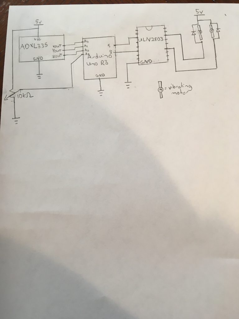
Schematic:
Code:
const int XPIN = A0;
const int YPIN = A1;
const int ZPIN = A2;
const int MOTOR_ONE = 8;
const int MOTOR_TWO = 5;
unsigned long timer = 0;
long wait = 5000;
int previousxValue = 0;
int previousyValue = 0;
int previouszValue = 0;
int potVal = 0;
int diffVal = 0;
bool Asleep = 0;

void setup() {
 pinMode(XPIN, INPUT);
 pinMode(YPIN, INPUT);
 pinMode(ZPIN, INPUT);
 pinMode(A3, INPUT);
 pinMode(MOTOR_ONE, OUTPUT);
 pinMode(MOTOR_TWO, OUTPUT);
 Serial.begin(9600);
}

void loop() {
 int XPINRead = analogRead(XPIN);
 int YPINRead = analogRead(YPIN);
 int ZPINRead = analogRead(ZPIN);
 Serial.println(String(XPINRead) + " " + String(YPINRead) + " " + String(ZPINRead));
 potVal = analogRead(A3);
 diffVal = map(potVal, 0, 1023, 0, 100);
 Serial.println("diffVal = " + String(diffVal));
 if (abs(XPINRead - previousxValue) <= diffVal && abs(YPINRead - previousyValue) <= diffVal \
 && abs(ZPINRead - previouszValue) <= diffVal){
   Serial.println("if statement, Asleep");
   if (Asleep == false){
    Asleep = true;
    timer = millis();
   }
 }
 else{
 Serial.println("else statement, NOT Asleep");
 Asleep = false;
 timer = 0;
 }
 if (Asleep && millis() - timer >= wait){
 digitalWrite(MOTOR_ONE, HIGH);
 digitalWrite(MOTOR_TWO, HIGH);
 Serial.println("timer = " + String(timer) + "millis = " + String(millis()));
 }
 else{
 digitalWrite(MOTOR_ONE, LOW);
 digitalWrite(MOTOR_TWO, LOW);
 }
 previousxValue = XPINRead;
 previousyValue = YPINRead;
 previouszValue = ZPINRead;
}
Leave a Reply
You must be logged in to post a comment.