
The “Don’t Be Like Jack” device alerts the user when it is time break from work and when it is time to go back to work.
The name of this project is inspired by a line from The Shining (1980): “All work and no play makes Jack a dull boy.” The name “Don’t be like Jack” reminds the user of the importance of taking breaks between long streches of work. In this set up, the user would work for 30 minutes and take a break for 10 minutes.
In the work mode, the LEDs light up one at a time in 3 minute increments.
When work time or break time is over, the LEDs will begin to flash until the user flicks the switch
The break mode starts with all LEDs on. After each minute, one LED goes out
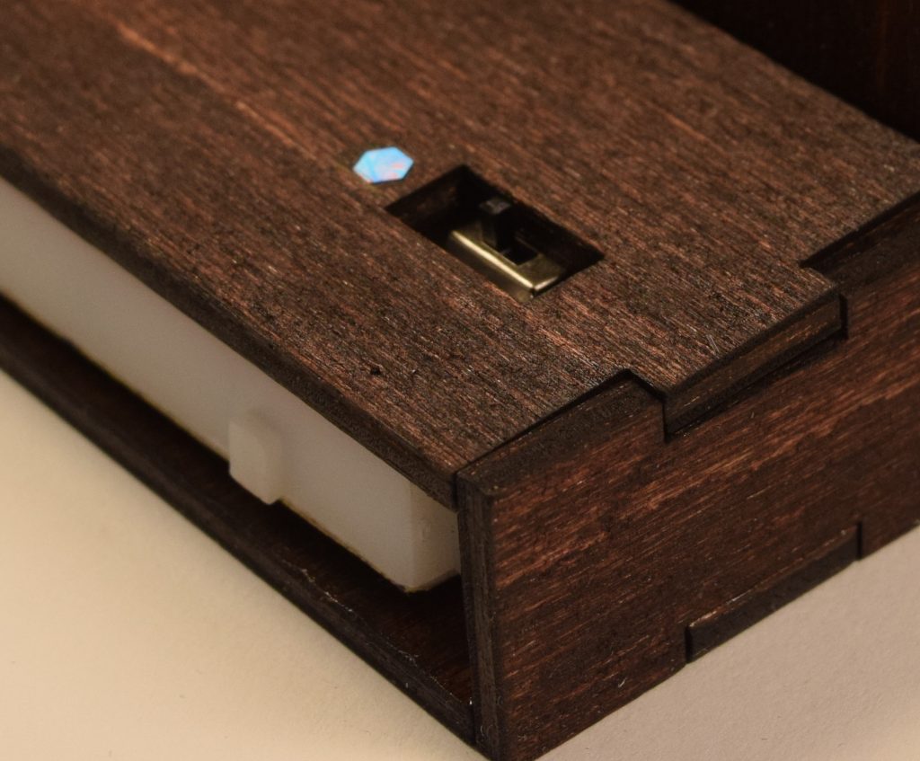
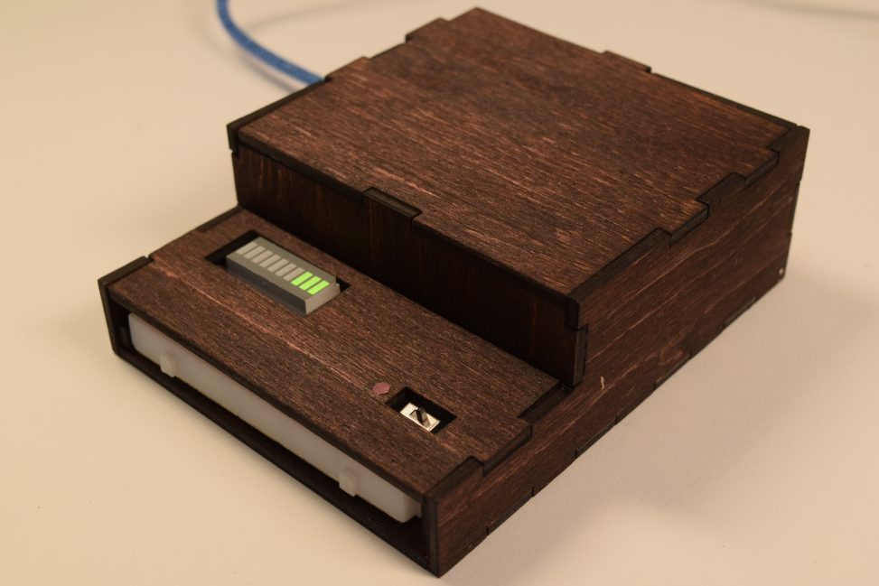
When the switch is on the side with the speck of glitter, it is in break mode. Otherwise, the device is in work mode.
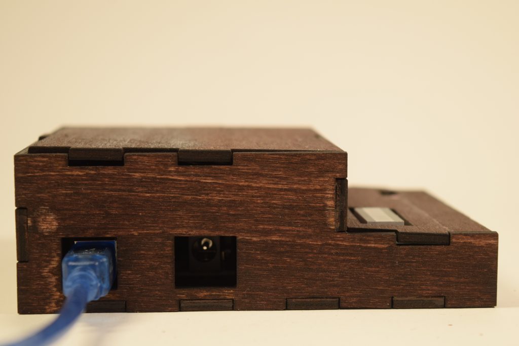
When in use, the device is plugged into a computer or laptop at all times. The built in holes for the USB cable connector and the power jack makes it easy for the user to power and modify the device.
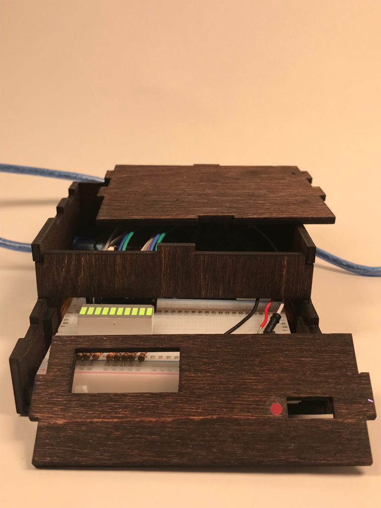
The top lids are removable so that there is easy access to the breadboard and Arduino.
Process
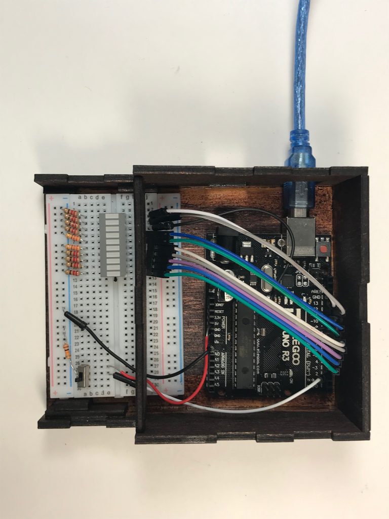
This overhead view shows the device in work mode. Approximately 9 minutes have passed.
There were two things I wanted to achieve with this device: 1) A simple design/interface, and 2) portablility and easy acccess.
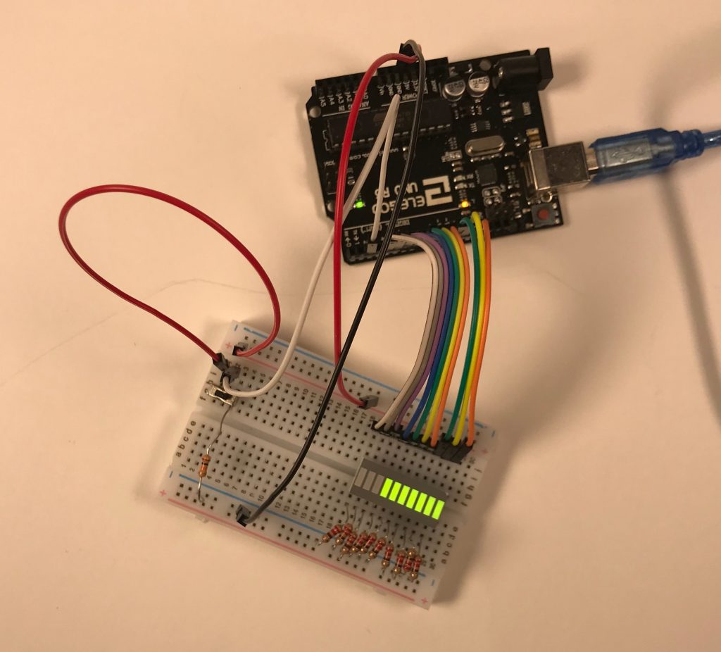
To get the simple interface, I decided to use an LED bar graph display to track the passing time. I quickly ruled out an audio signal because it would be too disruptive and irritating. The LED bar graph display was a favorable option because there is a built in separation between the LEDs. The separation makes it easier to signal the passage of time in a discrete and comprehensible manner. In other words, most users would be able to determine how much time has passed. As shown in the picture above, the clean wiring and minimal parts makes it easy to put the electrical components into a compact case.
I initially intended to solder the components to a breadboard to make the device more durable and permanent. However, two LEDs in the bar graph display stopped working and there wasn’t enough time to fix the problem. The iteration of this setup is shown below.
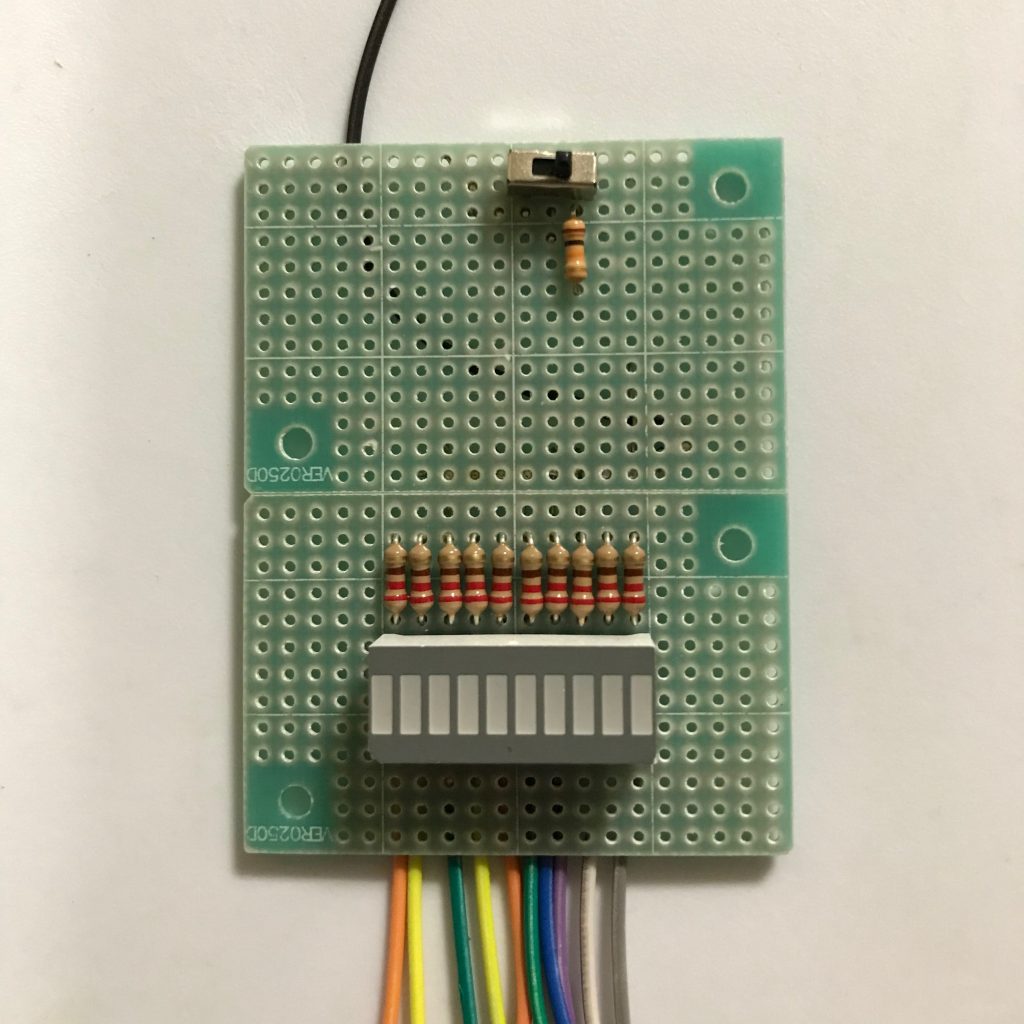
This is the intended setup for the switch and LED bar graph. Both components would take up less space in this set up than in the solderless breadboard set up.
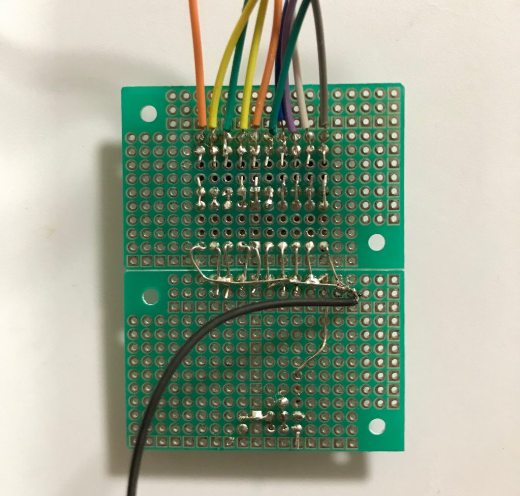
This is a closer look at the soldering done on the LED bar graph display and the switch. The soldering is a bit messy and there is a bad connection somewhere.
To keep the wiring and setup neat and organized, I placed ground on one side of the breadboard and power on the other side. Keeping these areas separate made it easier to avoid crossing wires. It also makes the LED bar graph display more visible, as shown in the picture below.
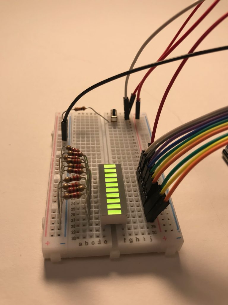
To maximize the space and minimize the clutter on the breadboard, the wires that address the LEDs are placed on the side closer to the Arduino.
The last step of this process was to create a container for this device. I lasercut a box with two removable lids so that the user has easy access to the Arduino and breadboard. That way, if there needs to be any modification or readjustment, both components can be removed efficiently. The lid that covers the breadboard has a larger rectangle that allows the user to see the LED bar graph, and a smaller rectangle that gives the user access to the switch. The container also has two rectangular holes on the left side so that the USB port and power jack are exposed.
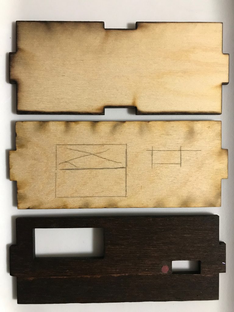
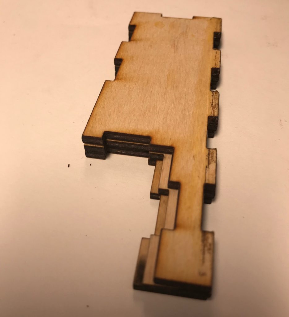
This shows the iteration process for the breadboard lid. The top shows the profile of the lid. The middle lid shows the approximate location of the LED bar graph display and the switch. The bottom picture shows the final result, after woodstaining and labeling one side of the switch.
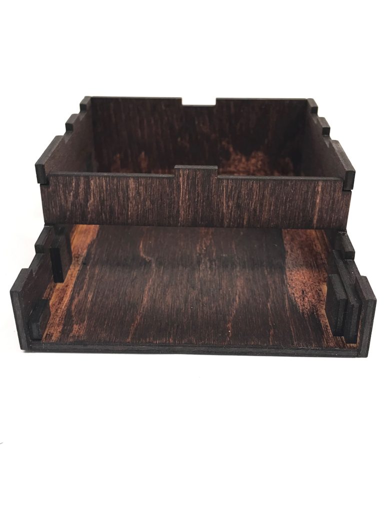
I ran into a couple problems with the breadboard side of the container. As shown in the picture below, I went through several iterations of side pieces because the breadboard was too tall for the lid to fit over the device.
The height differences between the iterations of the side pieces is small but significant. The bottom side piece ended up being the size I used for the container
To minimize sliding inside the case, I glued small wooden squares to both sides of the insider of the case.
I used a total of four tiny rectangles to orevent the breadboard from sliding side to side.
Finally, the resistors were cut down so that they laid flat on the breadboard. The longer wires were also replaced with shorter wires so that they could be compressed inside the container. By cutting down the size of the device in multiple areas, I was able to make the device as portable as it could be.
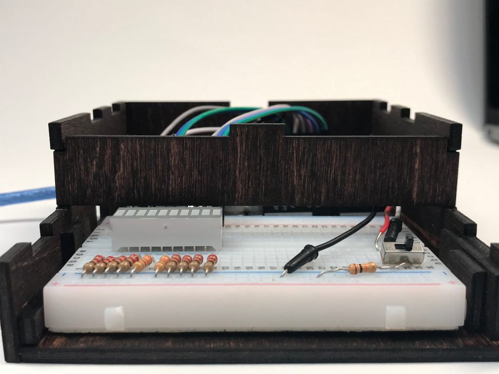
The resistors ad wires lay flat on the breadboard whereas the LED display and switch protrude more.
Here’s a final look at the insides if the device. Everything has to be neat and organized in order to conceal all the extra electrical parts.
Discussion
Looking at the final product, I am satisfied with the execution and simplicity of the work and break monitor. The LED bargraph display tracks the time passed in a nondistracting manner. The flashing LEDs that signal the end of the work/break period is noticeable without being obstrusive. The work/break monitor only has two main components: the switch and the LED bargraph. The simplicity of the algorithm contributed to the device’s “clean cut” look. Many peers complimented how “straightforward and clean cut both the concept and design were.” Some also added that the “dark wood stain looks really good” and “glitter icon is effective as well.” The dark wood stain made the final product look more polished. I am also glad that the glitter icon functioned as a personal touch and a distinction between the two modes.
While the overall display was clean and finished, there are two components of this device that I would modify. As one of my peers suggested, “covering up the front enclosure would have been nice.” Due to the current location of the LED bargraph hole on the lid, shifting the breadboard back to add a front cover would put the LED display off center. However, looking forward, all electronic parts should be concealed if it does not have to be seen. The second component that I would modify is the tiny slide switch. One of my peers mentioned that the “switch maybe could be replaced by a button. ” While I agree that the switch needs to be replaced, I don’t think a button would necessarily be the right option. The button state would be more visually ambiguous because the user doesn’t know the mode the device is in unless they understand the LED light sequence. However, using a bigger and more accessible switch would make it easier to operate the switch.
Although this device is relatively compact (approximately 5″ x 5″ x 2″), it can still be shrunken. The solderless breadboard took up more space than a soldering breadboard would. Since the device only needs to display a 10 LED bargraph display and a switch, I didn’t need that much surface area on the breadboard. Some of the feedback I received suggested that “It would be cool if this [the device] was super compact and only a couple square centimeters”. A compact version of this device is defintely an idea worth exploring because it would make the device more portable. The current device needs to rest on the table next to a laptop. If the device was small enough so that it rests on the laptop or small enough so that it doesn’t need a support on the bottom surface, it would be more portable. However, The next step would be to figure out how to create a device that is small enough to be a couple square centimeters but also large enough to house an Arudino Uno.
While making the CAD drawings for the device container, I found that it’s very difficult to get the right dimensions. I had to make multiple iterations of various pieces to account for the actual height of the electronic parts and the holes on the lids. Looking at my peers works, I would also like to try lasercutting different forms for future projects. Up until now, I have only made rectangular boxes that fit like a puzzle piece. Exploring other lasercutting methods can make my device look more dynamic.
I spend a good amount of time soldering the device and resoldering it when it did not work. It still didn’t work the after the second attempt. While this time could have been put into other areas of the project, I am glad I learned how to solder. enjoyed learning this new skill and I think with enough practice and care, my next attempt will be more sucessful.
The challenging part of this project was actually the code. Because all LEDs in the LED bargraph needed to be individually addressed, I used a for loop to control the LEDs. This means that I don’t have to call every single pin for every action. Getting the LEDs to light up (or go out) one at a time was simple. However, getting the LEDs to blink on and off after time was up was trickier because the blinking action requires a while loop that is constantly checking for a change in the switch state and several for loops to make the LEDs blink. In the future, I would use millis() to simplify the code. The millis() would eliminate the need for a waitMin() function. For reference, the waitMin() function delayed a given number of minutes.
Overall, I am happy with the way the project turned out. If I were to make improvements, I would cover up the exposed breadboard, solder the electronic components, and replace the tiny switch with a better switch. I would also custom fit the size of the LED bargraph and the switch with the lid and shrink, if possible, the overall size of the device. The things that would definitely stay are the dark woodstain and the glitter distinction.
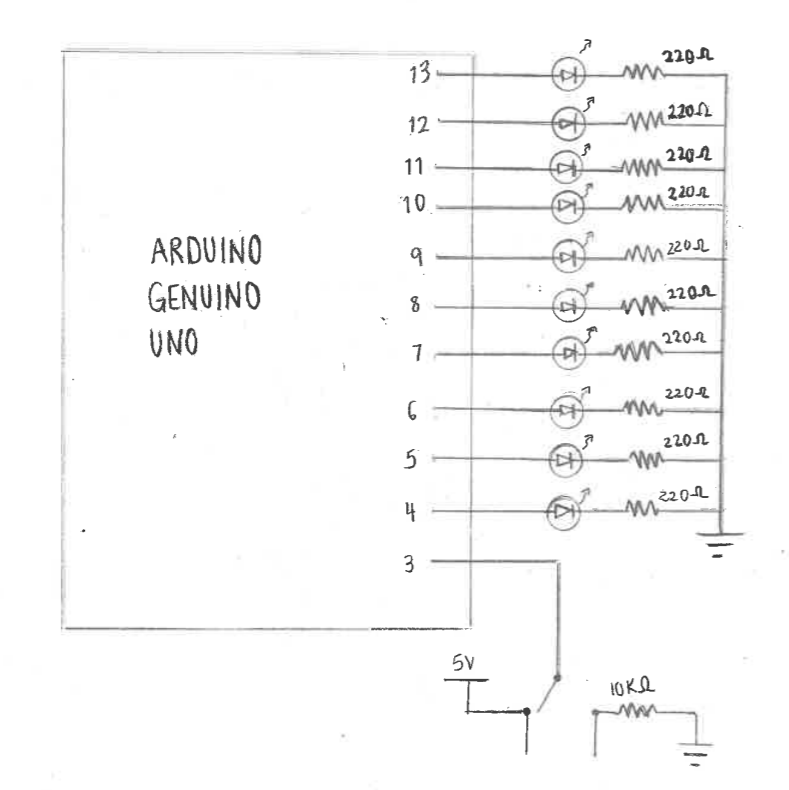
Schematic
Code
/*

Project Title: Don't Be Like Jack
Helen Yu

Description:
The code reads the position of a slideswitch to determine how to control the LED bargraph display. When the slideswitch is HIGH,the LEDs are on. They go out once every minute. When the slideswitch is LOW, the LEDs are off. One LED turns on every 3 minutes. The timed delay is controlled by the function waitMin(int n) which takes a integer n and delays for n minutes. This makes the coe easily adjustable for every user. The LEDs are placed inside an array called ledPins, making it easier to control the LEDs for the purpose of this device.

*/

const int ledCount = 10;
const int SLIDESWITCH = 3;
const int ledPins[] = {4, 5, 6, 7, 8, 9, 10, 11, 12, 13};

void setup() {
  pinMode(SLIDESWITCH, INPUT);
  // loop over the pin array and set them all to output
  for (int thisLed = 0; thisLed < ledCount; thisLed++) {
    pinMode(ledPins[thisLed], OUTPUT);
  }
  Serial.begin(9600);
}

// function that delays n minutes
void waitMin(int n) {
  for (int i = 0; i < n; i++) {
    delay(60000);
  }
}

void loop() {
  // read switch position
  int switchState;
  switchState = digitalRead(SLIDESWITCH);
  // Break Time (10 min)
  if (switchState == HIGH) {
    // All LEDs on. One LED goes out every minute.
    for (int thisLed = 0; thisLed < ledCount; thisLed++) {
      digitalWrite(ledPins[thisLed], HIGH);
    }
    delay(500);
    for (int thisLed = 0; thisLed < ledCount; thisLed++) {
      waitMin(1); // loop once through waitMin() before turning on an LED.
      digitalWrite(ledPins[thisLed], LOW);
    }
    // All LEDs blink until switch is flicked
    while (switchState == HIGH) {
      for (int thisLed = 0; thisLed < ledCount; thisLed++) {
        digitalWrite(ledPins[thisLed], HIGH);
      }
      delay(500);
      for (int thisLed = 0; thisLed < ledCount; thisLed++) {
        digitalWrite(ledPins[thisLed], LOW);
      }
      delay(500);
      //constantly read switch state to update while loop
      switchState = digitalRead(SLIDESWITCH);
    }
  }

  // Work Time (30 min)
  else if (switchState == LOW) {
    // All LEDs off. One LED turns on every 3 minutes.
    for (int thisLed = 0; thisLed < ledCount; thisLed++) {
      digitalWrite(ledPins[thisLed], LOW);
    }
    delay(500);
    for (int thisLed = 0; thisLed < ledCount; thisLed++) {
      waitMin(3);
      digitalWrite(ledPins[thisLed], HIGH);
    }
    // All LEDs blink until switch is flicked
    while (switchState == LOW) {
      for (int thisLed = 0; thisLed < ledCount; thisLed++) {
        digitalWrite(ledPins[thisLed], HIGH);
      }
      delay(500);
      for (int thisLed = 0; thisLed < ledCount; thisLed++) {
        digitalWrite(ledPins[thisLed], LOW);
      }
      delay(500);
      //constantly read switch state to update while loop
      switchState = digitalRead(SLIDESWITCH);
    }
  }
}
Comments are closed.