Hook:
Never forget an item again with this fully configurable item presence detector which uses RFID technology to detect whether your items are all present.
Description:
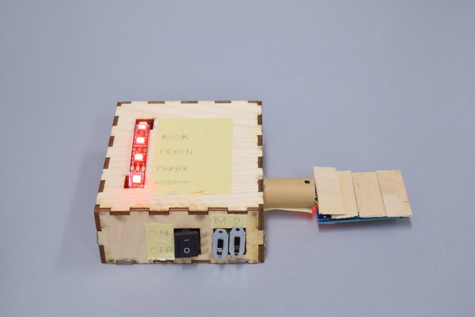
This detector helps ensure you don’t forget any important items regardless of the situation. It is fully configurable, allowing you to dynamically add or remove up to five unique items from its storage, and can also act as a portable scanner which you can use to scan your items to make sure nothing is missing. At its core, the device comprises of three integral components: an RFID reader, its configuration switches, and a LED display strip with erasable labels. The pictures below serve to illustrate each component, with additional explanations provided.
The RFID reader serves as the item presence detector’s information extractor. This module scans the environment for unseen items and feeds them to the device for processing. The image below illustrates how this component integrates with the device.
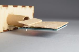
Housing of the device’s RFID reader.
The configuration component regulates the item presence detector’s usage mode through three switches: power, device mode (M), and data configuration mode (D). The power switch turns the device ‘on’ or ‘off’ based on the switch state, and is located on the left. We use quotations because in actuality, the device’s power state is determined by the presence of a battery, and not by a switch. However, our power switch emulates turning the device on or off by changing the LED strip display based on the switch state. For instance, turning the switch to ‘OFF’ turns the LEDs off, while ‘ON’ turns the LEDs on. The device mode switch, located in the middle, determines whether the device is in ‘detection mode’ (switch is down) or ‘configuration mode’ (switch is up). When the device is in detection mode, the user can search for items to detect as present. In configuration mode, the user can add or remove items based on their desire. Lastly, the third and right switch determines the configure data mode. This switch only impacts the device’s behavior if it is in ‘configure mode’. When the configure data mode switch is up (‘add’ mode), the user is able to add an item to device storage (provided space is available), while when it is down (‘delete’ mode) the user can remove an item from device storage (provided the item is stored on the device).
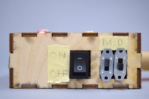
The device’s detection and configuration controls. In this case the device is on and in ‘detection mode’ (left switch is on, and middle switch is down).
The LED display strip with erasable labels lies on the face of the device, and each LED corresponds to a specific item labeled to its right. This serves as the primary source of feedback between the device and the user. When the device is initially turned on, all LEDs that correspond to stored items turn red indicating that the items are undetected, or missing. To determine which specific items the device has stored, the user can reference the labels on its face which are written to the right of the LEDs. Each LED to the left of an existing label denotes the status (missing or present) of the label, and those without a label are off which indicate free space in the device storage.
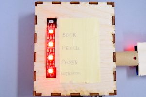
The device displays colored LEDs whose lights indicate an item’s presence. In this case all items are missing.
If the device is in ‘detection mode’, then the display serves to give the user feedback as to whether stored items are present. When a respective item is read by the RFID reader and processed by the device, the LED corresponding to the item turns green indicating the device has seen it. Otherwise, it remains red. The video following video showcases this feature.
Example usage of item presence detector in detection mode. The device actively searches for stored items and when found will indicate them using the display by turning green.
If the device is in ‘configuration mode’, the display instead serves to give the user feedback as to whether items have been added or deleted. When the item presence detector’s configuration mode is in ‘add’, the RFID reader scans the desired item to be added, and if space is available, adds it to the item presence detector’s storage memory. If the item was successfully added, the device provides user feedback to indicate this. See the video below for an illustration.
In the ‘add’ mode, the item presence detector scans the environment for the desired item, and adds it to storage provided space is available. A successful addition is indicated by the green light blinking, before changing to red.
If instead, the configuration mode is in ‘delete’ mode, then the item presence detector removes an item from storage. To do this, the RFID reader scans the desired item to be removed, and provided its stored in memory, it removes it from storage and gives feedback to the user. See the video below for an illustration.
The Item presence detector scans for the item to be removed, and provided it’s currently stored on the device, removes it from storage. A successful deletion is indicated by the red blinking of the item’s old respective LED.
The picture below showcases the wiring of the item presence detector, and illustrates why the box is so large: the external power source has a very long connection component to the Arduino uno, effectively constraining the box size to be at least as long as it.
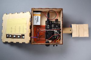
This view on the internal wiring illustrates the device’s circuitry as well as explains why the housing is the size it is. For instance, the external power source connection component extends past the entire rest of the device, forcing the housing to be at least as long as it.
Process Images and Review
While there were several decisions in designing the item presence detector, there were two which were integral to the ultimate product: moving from a bin shaped detector to a portable one, and adding configuration abilities to the device.
As seen in the image below, my initial proposition for the item presence detector was to have it shaped like a bin which a user can place their backpack on. The proposed model was to have several RFID readers spaced throughout the bin face which would simultaneously detect any items and cross check them with the device storage. Similar to how the ultimate product gives feedback, if an item was missing the corresponding LED would be red, while if it was present the LED would turn green. Unfortunately, RFID readers capable of reading simultaneous item signals (their respective RFID tags) are very expensive and our lab did not have any. Thus, I instead used the MFRC522 RFID readers, which are cheap alternative but which can only handle one RFID tag at once, provided that it was right on the reader. Due to this restriction, creating a bin shaped product no longer made sense because: 1) the RFID reader would not be able to detect far away RFID tags, and 2) the RFID reader would not be able to handle the potentially many items scattered around a backpack at once. Therefore, I adopted a portable detection design which ultimately became the chosen design for the product. This change let me to instead pass the item presence detector over each individual item which allowed my to overcome both limitations of the RFID reader.
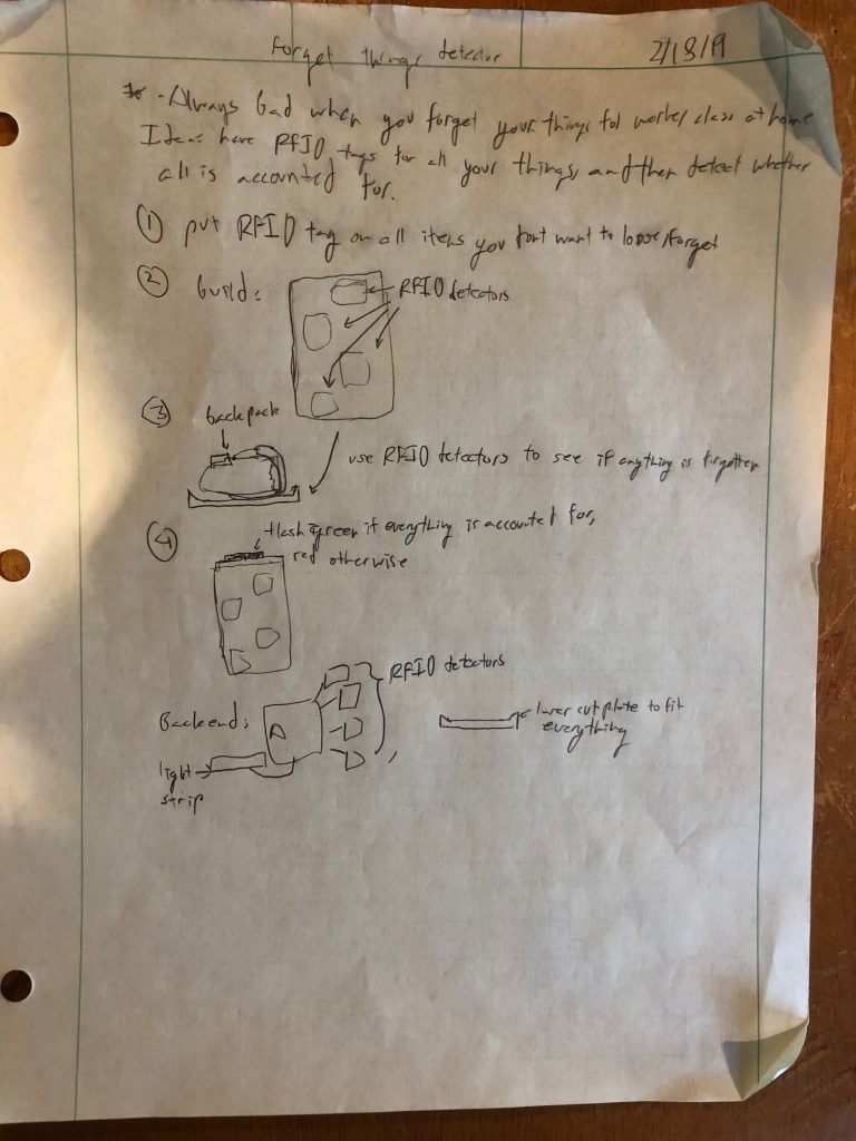
Initial idea of the item presence detector. I first thought of building a bin like product instead of the ultimate portable scanner device.
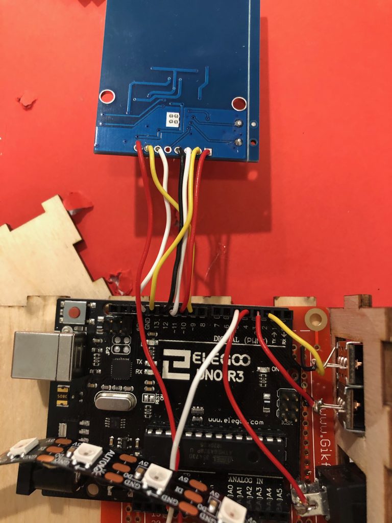
This image showcases the ultimate shape design of the item presence detector as a portable scanner. The RFID extends from the side of the Arduino uno at the top of the image, facing downwards.
Adding configuration capabilities also served as an integral design change for the final project. My initial proposal was to simply design a detection device which looked for certain predetermined items and checked if they were present (this is only the ‘detection mode’ in the final product). However, I realized in the process of the project creation that it would be more optimal and practical if the user would be given the flexibility of dynamically adding or removing items based on their needs personal needs. While this change would make the item presence detector more adaptive, it required substantial code logic change and additional circuitry. For instance, instead of having one device mode: detection, it would now have three which needed to be smartly nested within one another (‘add’ and ‘delete’ configuration data modes would only activate if the device was in ‘configuration mode’). The pictures below illustrate the change in terms of circuitry.
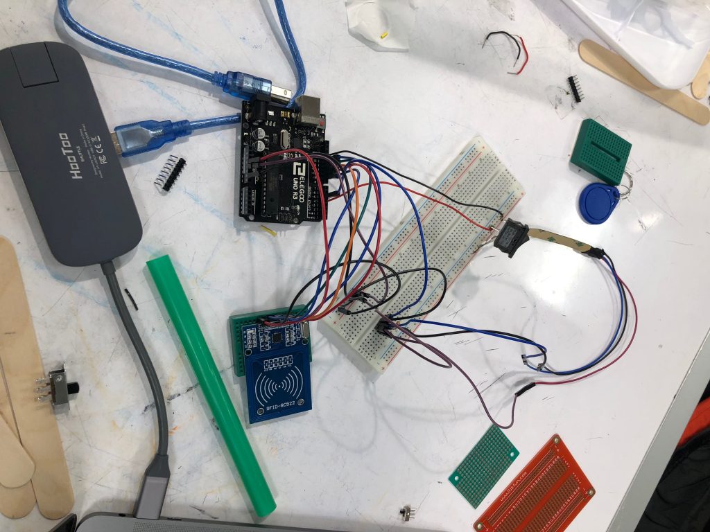
The initial single mode item presence detector (note the single switch). This iteration was only capable of detecting whether a preset number of objects were present or missing.
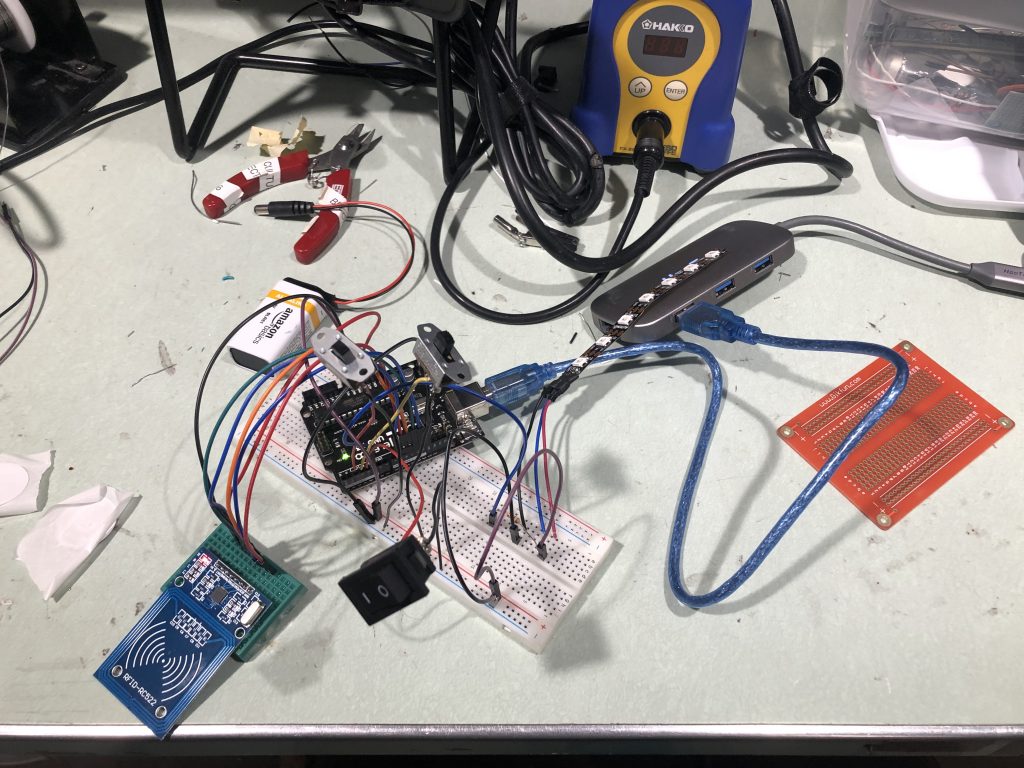
Preliminary three mode item presence detector (note the three switches). This iteration extended the device to be fully configurable.
Discussion:
Overall this project served as a great learning tool about the many facets of project creation. From the home works I was fairly comfortable with the hardware components, and from previous courses I understood programming, but I no experience in laser cutting, constructing physical products, or photography. In my tackling each of the latter three tasks, I consistently found that the time I expected to finish each should actually have been two to three times as long. While this was primarily due to my inexperience, it was also due to unknowns that could develop at anytime in the task. For instance, I spent six hours laser cutting the box that houses the Arduino and most circuitry. When I initially set about laser cutting, I designed a simple box on maker-case and brought it to the laser cutting open fabrication hours. In my time at the fabrication lab I learned how to create holes for my LEDs and switches using Solidworks, but not without many failures. It took me three tries to figure out that the reason my maker-case box kept getting corrupted in the program was because I was adding holes in the same layer as the box, instead of in different layers. Only to have the entire Solidworks program crash as soon as I tried saving a satisfactory box, forcing me to start over. Other instances of these unexpected setbacks included discovering that one of the holes I laser cut was one millimeter too thin, forcing me to chip away at it until it was large enough. Or finding that large discrepancies between pictures on the Nikon DSLR camera and my laptop, forcing me to reshoot the images. However, while each of these tasks presented difficulties and unexpected complications, they each served as valuable learning tools which I can now leverage on the next project or future hobby work to more efficiently complete each. Furthermore, they reinforced the idea that for any task, you should include a buffer time for setbacks in your schedule.
Despite the challenges faced during the project, I am happy with the final result. The item presence detector works exactly as intended, and allows for adapting to any user’s needs which was the ultimate goal. I believe the LED strip lighting and pattern indication for different modes are a good way to give instantaneous feedback to users. Similarly, the erasable labeling pad allows users to spontaneously change the items they want to remember in conjunction with the device. Furthermore, once a user understands the function of the device switches, altering the item presence detector’s modes can be done relatively effortlessly. However, there are a few things that could be improved. Firstly, the switch labels are not very intuitive or clear to non-trained users. For instance ‘M’ or ‘D’ are not very informative to as to what their respective switches do. Furthermore, the lack of space around the switches means that their states must be unlabeled, which forces users to consult a ‘manual’ if they forget what each state does. Additionally, a label contraption such as an erasable whiteboard cover would create a cleaner labelling process overall. This has the benefit that erasing labels leaves no trace, while erasing current labels leaves behind the pencil coloring. Moreover, the housing for the RFID reader is relatively haphazardly stuck together. While this was done because I was not able to laser cut a housing for the reader, it should be better put together.
Glancing at feedback from the project critique day, there were a couple critiques to mention. The first critique supports my three switch design, and my LED strip user feedback: “The dynamic adding and deleting is really clean and well-done. I like the LED strip as an output device, it conveys the meaning very clearly.” This is exactly what I had hoped for in creating the switch and LED strip logic, as well as their physical incorporations with the overall device. The end objective would be to create a fully fledged product based on the prototype shown, and this feedback indicates to me that the design is heading in the right direction. The second critique touches on the box size issue, previously discussed: “Very useful idea and works very smoothly good job! Maybe if it were smaller it would be more portable”. I entirely agree with this critique, one of my goals was to have a small compact item presence detector that is truly portable. However, due to the size of the external power source connector for the Arduino, the end product had to be two inches longer than it could have been otherwise. This limitation effectively doubled the length of the final product. At the time of creation I did not know this, but the professor noted that there was a different way to connect external power sources to the Arduino that bypass the limitation. For future work, I would explore idea.
Though the end objective of this project would be to build a new iteration of the item presence detector, I do not plan on moving forward with it at this time. Despite this, there are several aspects of the device that should be improved. Firstly, the device can and should be half as long as it is now. This can be achieved by leveraging the knowledge gained described in the previous paragraph. Secondly, the device should have a cleaner labeling interface. This can be achieved by either replacing the duct tape label pad with a whiteboard sticky surface, or adding an LCD display with a small keyboard. Thirdly, the RFID reader housing should be more well put together. This can be done through laser cutting a separate housing for it, or by integrating it with the larger Arduino housing. Fourthly, the device modes should either be better labeled or be placed such that there is enough space to label their respective functions. This can be done by reorganizing the location of the switches on the device. Fifthly, the housing should be upgraded to a more durable material for daily use any any environment. Sixthly, the LED strip should have an encasing, such as a light defuser to remove it from being exposed to the elements of the environment. Each of these changes would be made in the next iteration for a more flushed out product.
Schematic:
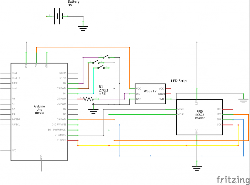
This image describes the full schematic of the device.
Code:
- <span class="com">/*
- * Project title: Item Presence Detector
- *
- * Code functionality: This code contains the program needed to run the item
- * presence detector. At a high level, the code revolves around three lists
- * which encode different information about items in the device storage:
- * 1) item RFID tag id, 2) item status, 3) LED status. Based on which mode
- * the device is, detection mode, configure data by adding mode, or configure
- * data by deleting mode, each list is updated respectively. For instance,
- * if an item in storage is present in detection mode, then the item's status
- * in the item status list and its corresponding LED status will be updated.
- * Each variable and loop is detailed with explanations for their purposes and
- * flow below, so for a more granular view on the program logic, please see below.
- *
- * Inputs: This code takes four inputs: an RFID scanner, and three switches.
- * Output: This code has a single output comprised of an LED strip.
- *
- * Credit: This code contains a block which is taken from a tutorial on using the
- * MFRC522 rfid scanner. I have sectioned off the respective block between '###'
- * statements, and given credit to the source in that section. However, the link
- * can also be reached here:
- * https://randomnerdtutorials.com/security-access-using-mfrc522-rfid-reader-with-arduino/
- *
- */</span><span class="pln">
- </span><span class="com">// Include necessary packages </span><span class="pln">
- </span><span class="com">#include</span><span class="pln"> </span><span class="str"><SPI.h></span><span class="pln">
- </span><span class="com">#include</span><span class="pln"> </span><span class="str"><MFRC522.h></span><span class="pln">
- </span><span class="com">#include</span><span class="pln"> </span><span class="str"><FastLED.h></span><span class="pln">
- </span><span class="com">// Define RFID scanner pins</span><span class="pln">
- </span><span class="com">#define</span><span class="pln"> SS_PIN </span><span class="lit">10</span><span class="pln">
- </span><span class="com">#define</span><span class="pln"> RST_PIN </span><span class="lit">9</span><span class="pln">
- </span><span class="com">// Define LED strip reader pin</span><span class="pln">
- </span><span class="com">#define</span><span class="pln"> LED_STRIP_PIN </span><span class="lit">5</span><span class="pln">
- </span><span class="com">// Create RFID scanner (MFRC522) instance.</span><span class="pln">
- MFRC522 mfrc522</span><span class="pun">(</span><span class="pln">SS_PIN</span><span class="pun">,</span><span class="pln"> RST_PIN</span><span class="pun">);</span><span class="pln">
- </span><span class="kwd">const</span><span class="pln"> </span><span class="kwd">int</span><span class="pln"> MEMORY_SIZE </span><span class="pun">=</span><span class="pln"> </span><span class="lit">5</span><span class="pun">;</span><span class="pln"> </span><span class="com">// Memory storage size. Equivalent to length</span><span class="pln">
- </span><span class="com">// of LED strip.</span><span class="pln">
- </span><span class="com">// Initialize list containing all RFID tags currently in memory storage. Each </span><span class="pln">
- </span><span class="com">// tag corresponds to a specific item. We can store a max of MEMORY_SIZE items.</span><span class="pln">
- </span><span class="typ">String</span><span class="pln"> RFID_TAGS</span><span class="pun">[</span><span class="pln">MEMORY_SIZE</span><span class="pun">]</span><span class="pln"> </span><span class="pun">=</span><span class="pln"> </span><span class="pun">{</span><span class="str">"05 51 5C C9"</span><span class="pun">,</span><span class="pln"> </span><span class="str">"D5 05 5A C9"</span><span class="pun">,</span><span class="pln"> </span><span class="str">"C5 29 5E C9"</span><span class="pun">};</span><span class="pln">
- </span><span class="com">// Initialize LED strip of size MEMORY_SIZE where each index corresponds to a</span><span class="pln">
- </span><span class="com">// potential RFID item and denotes the color the device displays.</span><span class="pln">
- CRGB LED_STRIP</span><span class="pun">[</span><span class="pln">MEMORY_SIZE</span><span class="pun">];</span><span class="pln">
- </span><span class="com">// Initialize an item status, which denotes whether an item has been </span><span class="pln">
- </span><span class="com">// unassigned (0), assigned and missing (1), or assigned and present (2).</span><span class="pln">
- </span><span class="com">// Based on the item status, the LEDs will change colors. If the item is </span><span class="pln">
- </span><span class="com">// unassigned, the corresponding LED will be black, if it missing the LED</span><span class="pln">
- </span><span class="com">// will be red, and if it is present the LED will be green.</span><span class="pln">
- </span><span class="kwd">int</span><span class="pln"> ITEM_STATUS</span><span class="pun">[</span><span class="pln">MEMORY_SIZE</span><span class="pun">]</span><span class="pln"> </span><span class="pun">=</span><span class="pln"> </span><span class="pun">{</span><span class="lit">1</span><span class="pun">,</span><span class="pln"> </span><span class="lit">1</span><span class="pun">,</span><span class="pln"> </span><span class="lit">1</span><span class="pun">};</span><span class="pln"> </span><span class="com">// 0: unassigned </span><span class="pln">
- </span><span class="com">// 1: missing </span><span class="pln">
- </span><span class="com">// 2: present</span><span class="pln">
- </span><span class="com">// Initialize device mode pins</span><span class="pln">
- </span><span class="kwd">int</span><span class="pln"> POWER_PIN </span><span class="pun">=</span><span class="pln"> </span><span class="lit">4</span><span class="pun">;</span><span class="pln"> </span><span class="com">// Reads device power state (on or off)</span><span class="pln">
- </span><span class="kwd">int</span><span class="pln"> DATA_MODE </span><span class="pun">=</span><span class="pln"> </span><span class="lit">3</span><span class="pun">;</span><span class="pln"> </span><span class="com">// Reads device mode (detection or configure)</span><span class="pln">
- </span><span class="kwd">int</span><span class="pln"> ADD_DEL_DATA </span><span class="pun">=</span><span class="pln"> </span><span class="lit">2</span><span class="pun">;</span><span class="pln"> </span><span class="com">// Reads device configure data mode (add or delete)</span><span class="pln">
- </span><span class="kwd">void</span><span class="pln"> setup</span><span class="pun">()</span><span class="pln">
- </span><span class="pun">{</span><span class="pln">
- </span><span class="com">// Initialize led strip functionality </span><span class="pln">
- </span><span class="typ">FastLED</span><span class="pun">.</span><span class="pln">addLeds</span><span class="pun"><</span><span class="pln">NEOPIXEL</span><span class="pun">,</span><span class="pln"> LED_STRIP_PIN</span><span class="pun">>(</span><span class="pln">LED_STRIP</span><span class="pun">,</span><span class="pln"> MEMORY_SIZE</span><span class="pun">);</span><span class="pln">
- </span><span class="typ">Serial</span><span class="pun">.</span><span class="kwd">begin</span><span class="pun">(</span><span class="lit">9600</span><span class="pun">);</span><span class="pln"> </span><span class="com">// Initiate a serial communication</span><span class="pln">
- SPI</span><span class="pun">.</span><span class="kwd">begin</span><span class="pun">();</span><span class="pln"> </span><span class="com">// Initiate SPI bus</span><span class="pln">
- mfrc522</span><span class="pun">.</span><span class="pln">PCD_Init</span><span class="pun">();</span><span class="pln"> </span><span class="com">// Initiate MFRC522</span><span class="pln">
- </span><span class="com">// Store pin modes for device modes.</span><span class="pln">
- pinMode</span><span class="pun">(</span><span class="pln">POWER_PIN</span><span class="pun">,</span><span class="pln"> INPUT_PULLUP</span><span class="pun">);</span><span class="pln">
- pinMode</span><span class="pun">(</span><span class="pln">ADD_DEL_DATA</span><span class="pun">,</span><span class="pln"> INPUT_PULLUP</span><span class="pun">);</span><span class="pln">
- pinMode</span><span class="pun">(</span><span class="pln">DATA_MODE</span><span class="pun">,</span><span class="pln"> INPUT_PULLUP</span><span class="pun">);</span><span class="pln">
- </span><span class="pun">}</span><span class="pln">
- </span><span class="kwd">void</span><span class="pln"> loop</span><span class="pun">()</span><span class="pln">
- </span><span class="pun">{</span><span class="pln">
- </span><span class="com">// read device power state</span><span class="pln">
- </span><span class="kwd">int</span><span class="pln"> current_power_state </span><span class="pun">=</span><span class="pln"> digitalRead</span><span class="pun">(</span><span class="pln">POWER_PIN</span><span class="pun">);</span><span class="pln">
- </span><span class="com">// Device is on</span><span class="pln">
- </span><span class="kwd">if</span><span class="pln"> </span><span class="pun">(</span><span class="pln">current_power_state </span><span class="pun">==</span><span class="pln"> LOW</span><span class="pun">)</span><span class="pln"> </span><span class="pun">{</span><span class="pln">
- </span><span class="com">// Set led strip colors according to item status</span><span class="pln">
- </span><span class="kwd">for</span><span class="pln"> </span><span class="pun">(</span><span class="kwd">int</span><span class="pln"> i </span><span class="pun">=</span><span class="pln"> </span><span class="lit">0</span><span class="pun">;</span><span class="pln"> i </span><span class="pun"><</span><span class="pln"> MEMORY_SIZE</span><span class="pun">;</span><span class="pln"> i </span><span class="pun">++)</span><span class="pln"> </span><span class="pun">{</span><span class="pln">
- </span><span class="kwd">int</span><span class="pln"> current_item_status </span><span class="pun">=</span><span class="pln"> ITEM_STATUS</span><span class="pun">[</span><span class="pln">i</span><span class="pun">];</span><span class="pln">
- </span><span class="com">// Item is unassigned, make corresponding LED black</span><span class="pln">
- </span><span class="kwd">if</span><span class="pln"> </span><span class="pun">(</span><span class="pln">current_item_status </span><span class="pun">==</span><span class="pln"> </span><span class="lit">0</span><span class="pun">)</span><span class="pln"> </span><span class="pun">{</span><span class="pln">
- LED_STRIP</span><span class="pun">[</span><span class="pln">i</span><span class="pun">]</span><span class="pln"> </span><span class="pun">=</span><span class="pln"> CRGB</span><span class="pun">::</span><span class="typ">Black</span><span class="pun">;</span><span class="pln">
- </span><span class="pun">}</span><span class="pln">
- </span><span class="com">// Item is missing, make corresponding LED red</span><span class="pln">
- </span><span class="kwd">else</span><span class="pln"> </span><span class="kwd">if</span><span class="pln"> </span><span class="pun">(</span><span class="pln">current_item_status </span><span class="pun">==</span><span class="pln"> </span><span class="lit">1</span><span class="pun">)</span><span class="pln"> </span><span class="pun">{</span><span class="pln">
- LED_STRIP</span><span class="pun">[</span><span class="pln">i</span><span class="pun">]</span><span class="pln"> </span><span class="pun">=</span><span class="pln"> CRGB</span><span class="pun">::</span><span class="typ">Red</span><span class="pun">;</span><span class="pln">
- </span><span class="pun">}</span><span class="pln">
- </span><span class="com">// Item is present, make corresponding LED green</span><span class="pln">
- </span><span class="kwd">else</span><span class="pln"> </span><span class="pun">{</span><span class="pln">
- LED_STRIP</span><span class="pun">[</span><span class="pln">i</span><span class="pun">]</span><span class="pln"> </span><span class="pun">=</span><span class="pln"> CRGB</span><span class="pun">::</span><span class="typ">Green</span><span class="pun">;</span><span class="pln">
- </span><span class="pun">}</span><span class="pln">
- </span><span class="com">// display LED color assignments</span><span class="pln">
- </span><span class="typ">FastLED</span><span class="pun">.</span><span class="pln">show</span><span class="pun">();</span><span class="pln">
- </span><span class="pun">}</span><span class="pln">
- </span><span class="com">// Search for RFID item</span><span class="pln">
- </span><span class="kwd">if</span><span class="pln"> </span><span class="pun">(</span><span class="pln"> </span><span class="pun">!</span><span class="pln"> mfrc522</span><span class="pun">.</span><span class="pln">PICC_IsNewCardPresent</span><span class="pun">())</span><span class="pln">
- </span><span class="pun">{</span><span class="pln">
- </span><span class="kwd">return</span><span class="pun">;</span><span class="pln">
- </span><span class="pun">}</span><span class="pln">
- </span><span class="com">// RFID item is present, select it.</span><span class="pln">
- </span><span class="kwd">if</span><span class="pln"> </span><span class="pun">(</span><span class="pln"> </span><span class="pun">!</span><span class="pln"> mfrc522</span><span class="pun">.</span><span class="pln">PICC_ReadCardSerial</span><span class="pun">())</span><span class="pln">
- </span><span class="pun">{</span><span class="pln">
- </span><span class="kwd">return</span><span class="pun">;</span><span class="pln">
- </span><span class="pun">}</span><span class="pln">
- </span><span class="com">// ####################################################################################### //</span><span class="pln">
- </span><span class="com">// ############### Code in this block is taken from the following website: ############### //</span><span class="pln">
- </span><span class="com">// https://randomnerdtutorials.com/security-access-using-mfrc522-rfid-reader-with-arduino/ //</span><span class="pln">
- </span><span class="com">// initialize RFID item id storage variables.</span><span class="pln">
- </span><span class="typ">String</span><span class="pln"> content</span><span class="pun">=</span><span class="pln"> </span><span class="str">""</span><span class="pun">;</span><span class="pln">
- </span><span class="kwd">byte</span><span class="pln"> letter</span><span class="pun">;</span><span class="pln">
- </span><span class="com">// Read bytes from RFID items.</span><span class="pln">
- </span><span class="kwd">for</span><span class="pln"> </span><span class="pun">(</span><span class="kwd">byte</span><span class="pln"> i </span><span class="pun">=</span><span class="pln"> </span><span class="lit">0</span><span class="pun">;</span><span class="pln"> i </span><span class="pun"><</span><span class="pln"> mfrc522</span><span class="pun">.</span><span class="pln">uid</span><span class="pun">.</span><span class="pln">size</span><span class="pun">;</span><span class="pln"> i</span><span class="pun">++)</span><span class="pln">
- </span><span class="pun">{</span><span class="pln">
- </span><span class="typ">Serial</span><span class="pun">.</span><span class="kwd">print</span><span class="pun">(</span><span class="pln">mfrc522</span><span class="pun">.</span><span class="pln">uid</span><span class="pun">.</span><span class="pln">uidByte</span><span class="pun">[</span><span class="pln">i</span><span class="pun">]</span><span class="pln"> </span><span class="pun"><</span><span class="pln"> </span><span class="lit">0x10</span><span class="pln"> </span><span class="pun">?</span><span class="pln"> </span><span class="str">" 0"</span><span class="pln"> </span><span class="pun">:</span><span class="pln"> </span><span class="str">" "</span><span class="pun">);</span><span class="pln">
- </span><span class="typ">Serial</span><span class="pun">.</span><span class="kwd">print</span><span class="pun">(</span><span class="pln">mfrc522</span><span class="pun">.</span><span class="pln">uid</span><span class="pun">.</span><span class="pln">uidByte</span><span class="pun">[</span><span class="pln">i</span><span class="pun">],</span><span class="pln"> HEX</span><span class="pun">);</span><span class="pln">
- content</span><span class="pun">.</span><span class="pln">concat</span><span class="pun">(</span><span class="typ">String</span><span class="pun">(</span><span class="pln">mfrc522</span><span class="pun">.</span><span class="pln">uid</span><span class="pun">.</span><span class="pln">uidByte</span><span class="pun">[</span><span class="pln">i</span><span class="pun">]</span><span class="pln"> </span><span class="pun"><</span><span class="pln"> </span><span class="lit">0x10</span><span class="pln"> </span><span class="pun">?</span><span class="pln"> </span><span class="str">" 0"</span><span class="pln"> </span><span class="pun">:</span><span class="pln"> </span><span class="str">" "</span><span class="pun">));</span><span class="pln">
- content</span><span class="pun">.</span><span class="pln">concat</span><span class="pun">(</span><span class="typ">String</span><span class="pun">(</span><span class="pln">mfrc522</span><span class="pun">.</span><span class="pln">uid</span><span class="pun">.</span><span class="pln">uidByte</span><span class="pun">[</span><span class="pln">i</span><span class="pun">],</span><span class="pln"> HEX</span><span class="pun">));</span><span class="pln">
- </span><span class="pun">}</span><span class="pln">
- </span><span class="com">// Convert RFID item id to uppercase for comparisons.</span><span class="pln">
- content</span><span class="pun">.</span><span class="pln">toUpperCase</span><span class="pun">();</span><span class="pln">
- </span><span class="com">// ####################################################################################### //</span><span class="pln">
- </span><span class="com">// Device is in configure data mode</span><span class="pln">
- </span><span class="kwd">if</span><span class="pln"> </span><span class="pun">(</span><span class="pln">digitalRead</span><span class="pun">(</span><span class="pln">DATA_MODE</span><span class="pun">)</span><span class="pln"> </span><span class="pun">==</span><span class="pln"> HIGH</span><span class="pun">)</span><span class="pln"> </span><span class="pun">{</span><span class="pln">
- </span><span class="com">// Configure data mode is set to add data</span><span class="pln">
- </span><span class="kwd">if</span><span class="pln"> </span><span class="pun">(</span><span class="pln">digitalRead</span><span class="pun">(</span><span class="pln">ADD_DEL_DATA</span><span class="pun">)</span><span class="pln"> </span><span class="pun">==</span><span class="pln"> HIGH</span><span class="pun">)</span><span class="pln"> </span><span class="pun">{</span><span class="pln">
- </span><span class="com">// Flag checking if we have added item</span><span class="pln">
- </span><span class="kwd">bool</span><span class="pln"> added_flag </span><span class="pun">=</span><span class="pln"> </span><span class="kwd">false</span><span class="pun">;</span><span class="pln">
- </span><span class="com">// Avoid adding duplicate items</span><span class="pln">
- </span><span class="kwd">for</span><span class="pln"> </span><span class="pun">(</span><span class="kwd">int</span><span class="pln"> i </span><span class="pun">=</span><span class="pln"> </span><span class="lit">0</span><span class="pun">;</span><span class="pln"> i </span><span class="pun"><</span><span class="pln"> MEMORY_SIZE</span><span class="pun">;</span><span class="pln"> i</span><span class="pun">++)</span><span class="pln"> </span><span class="pun">{</span><span class="pln">
- </span><span class="com">// Item is already stored on device</span><span class="pln">
- </span><span class="kwd">if</span><span class="pln"> </span><span class="pun">(</span><span class="pln">RFID_TAGS</span><span class="pun">[</span><span class="pln">i</span><span class="pun">]</span><span class="pln"> </span><span class="pun">==</span><span class="pln"> content</span><span class="pun">.</span><span class="pln">substring</span><span class="pun">(</span><span class="lit">1</span><span class="pun">))</span><span class="pln"> </span><span class="pun">{</span><span class="pln">
- </span><span class="com">// Item has already been added</span><span class="pln">
- added_flag </span><span class="pun">=</span><span class="pln"> </span><span class="kwd">true</span><span class="pun">;</span><span class="pln">
- </span><span class="pun">}</span><span class="pln">
- </span><span class="pun">}</span><span class="pln">
- </span><span class="com">// Add item to device storage</span><span class="pln">
- </span><span class="kwd">for</span><span class="pln"> </span><span class="pun">(</span><span class="kwd">int</span><span class="pln"> i </span><span class="pun">=</span><span class="pln"> </span><span class="lit">0</span><span class="pun">;</span><span class="pln"> i </span><span class="pun"><</span><span class="pln"> MEMORY_SIZE</span><span class="pun">;</span><span class="pln"> i</span><span class="pun">++)</span><span class="pln"> </span><span class="pun">{</span><span class="pln">
- </span><span class="typ">String</span><span class="pln"> rfid_tag </span><span class="pun">=</span><span class="pln"> RFID_TAGS</span><span class="pun">[</span><span class="pln">i</span><span class="pun">];</span><span class="pln"> </span><span class="com">// current search item id</span><span class="pln">
- </span><span class="com">// Space exists on device and we have not added the item yet</span><span class="pln">
- </span><span class="kwd">if</span><span class="pln"> </span><span class="pun">((</span><span class="pln">rfid_tag </span><span class="pun">==</span><span class="pln"> </span><span class="str">""</span><span class="pun">)</span><span class="pln"> </span><span class="pun">&&</span><span class="pln"> </span><span class="pun">(</span><span class="pln">added_flag </span><span class="pun">==</span><span class="pln"> </span><span class="kwd">false</span><span class="pun">))</span><span class="pln"> </span><span class="pun">{</span><span class="pln">
- </span><span class="com">// Store item RFID tag id in device storage</span><span class="pln">
- RFID_TAGS</span><span class="pun">[</span><span class="pln">i</span><span class="pun">]</span><span class="pln"> </span><span class="pun">=</span><span class="pln"> content</span><span class="pun">.</span><span class="pln">substring</span><span class="pun">(</span><span class="lit">1</span><span class="pun">);</span><span class="pln">
- </span><span class="com">// Set the item status to missing (default)</span><span class="pln">
- ITEM_STATUS</span><span class="pun">[</span><span class="pln">i</span><span class="pun">]</span><span class="pln"> </span><span class="pun">=</span><span class="pln"> </span><span class="lit">1</span><span class="pun">;</span><span class="pln">
- </span><span class="com">// Give user feedback that the item has been added</span><span class="pln">
- LED_STRIP</span><span class="pun">[</span><span class="pln">i</span><span class="pun">]</span><span class="pln"> </span><span class="pun">=</span><span class="pln"> CRGB</span><span class="pun">::</span><span class="typ">Green</span><span class="pun">;</span><span class="pln">
- </span><span class="typ">FastLED</span><span class="pun">.</span><span class="pln">show</span><span class="pun">();</span><span class="pln">
- delay</span><span class="pun">(</span><span class="lit">200</span><span class="pun">);</span><span class="pln">
- LED_STRIP</span><span class="pun">[</span><span class="pln">i</span><span class="pun">]</span><span class="pln"> </span><span class="pun">=</span><span class="pln"> CRGB</span><span class="pun">::</span><span class="typ">Black</span><span class="pun">;</span><span class="pln">
- </span><span class="typ">FastLED</span><span class="pun">.</span><span class="pln">show</span><span class="pun">();</span><span class="pln">
- delay</span><span class="pun">(</span><span class="lit">200</span><span class="pun">);</span><span class="pln">
- </span><span class="com">// Update flag to denote item has been added</span><span class="pln">
- added_flag </span><span class="pun">=</span><span class="pln"> </span><span class="kwd">true</span><span class="pun">;</span><span class="pln">
- </span><span class="pun">}</span><span class="pln">
- </span><span class="pun">}</span><span class="pln">
- </span><span class="pun">}</span><span class="pln">
- </span><span class="com">// Configure mode is set to delete data</span><span class="pln">
- </span><span class="kwd">else</span><span class="pln"> </span><span class="pun">{</span><span class="pln">
- </span><span class="com">// search through device storage for item to be deleted</span><span class="pln">
- </span><span class="kwd">for</span><span class="pln"> </span><span class="pun">(</span><span class="kwd">int</span><span class="pln"> i </span><span class="pun">=</span><span class="pln"> </span><span class="lit">0</span><span class="pun">;</span><span class="pln"> i </span><span class="pun"><</span><span class="pln"> MEMORY_SIZE</span><span class="pun">;</span><span class="pln"> i</span><span class="pun">++)</span><span class="pln"> </span><span class="pun">{</span><span class="pln">
- </span><span class="typ">String</span><span class="pln"> rfid_tag </span><span class="pun">=</span><span class="pln"> RFID_TAGS</span><span class="pun">[</span><span class="pln">i</span><span class="pun">];</span><span class="pln">
- </span><span class="com">// Item to be deleted has been found</span><span class="pln">
- </span><span class="kwd">if</span><span class="pln"> </span><span class="pun">(</span><span class="pln">rfid_tag </span><span class="pun">==</span><span class="pln"> content</span><span class="pun">.</span><span class="pln">substring</span><span class="pun">(</span><span class="lit">1</span><span class="pun">))</span><span class="pln"> </span><span class="pun">{</span><span class="pln">
- </span><span class="com">// Remove item RFID tag id from storage</span><span class="pln">
- RFID_TAGS</span><span class="pun">[</span><span class="pln">i</span><span class="pun">]</span><span class="pln"> </span><span class="pun">=</span><span class="pln"> </span><span class="str">""</span><span class="pun">;</span><span class="pln">
- </span><span class="com">// Unassign item</span><span class="pln">
- ITEM_STATUS</span><span class="pun">[</span><span class="pln">i</span><span class="pun">]</span><span class="pln"> </span><span class="pun">=</span><span class="pln"> </span><span class="lit">0</span><span class="pun">;</span><span class="pln">
- </span><span class="com">// Give user feedback that item has been deleted</span><span class="pln">
- LED_STRIP</span><span class="pun">[</span><span class="pln">i</span><span class="pun">]</span><span class="pln"> </span><span class="pun">=</span><span class="pln"> CRGB</span><span class="pun">::</span><span class="typ">Red</span><span class="pun">;</span><span class="pln">
- </span><span class="typ">FastLED</span><span class="pun">.</span><span class="pln">show</span><span class="pun">();</span><span class="pln">
- delay</span><span class="pun">(</span><span class="lit">200</span><span class="pun">);</span><span class="pln">
- LED_STRIP</span><span class="pun">[</span><span class="pln">i</span><span class="pun">]</span><span class="pln"> </span><span class="pun">=</span><span class="pln"> CRGB</span><span class="pun">::</span><span class="typ">Black</span><span class="pun">;</span><span class="pln">
- </span><span class="typ">FastLED</span><span class="pun">.</span><span class="pln">show</span><span class="pun">();</span><span class="pln">
- delay</span><span class="pun">(</span><span class="lit">200</span><span class="pun">);</span><span class="pln">
- </span><span class="pun">}</span><span class="pln">
- </span><span class="pun">}</span><span class="pln">
- </span><span class="pun">}</span><span class="pln">
- </span><span class="pun">}</span><span class="pln">
- </span><span class="com">// Device is in item detection mode</span><span class="pln">
- </span><span class="kwd">else</span><span class="pln"> </span><span class="pun">{</span><span class="pln">
- </span><span class="com">// Search device storage for item detected by RFID scanner</span><span class="pln">
- </span><span class="kwd">for</span><span class="pln"> </span><span class="pun">(</span><span class="kwd">int</span><span class="pln"> i </span><span class="pun">=</span><span class="pln"> </span><span class="lit">0</span><span class="pun">;</span><span class="pln"> i </span><span class="pun"><</span><span class="pln"> MEMORY_SIZE</span><span class="pun">;</span><span class="pln"> i</span><span class="pun">++)</span><span class="pln"> </span><span class="pun">{</span><span class="pln">
- </span><span class="com">// Item has been found in storage</span><span class="pln">
- </span><span class="kwd">if</span><span class="pln"> </span><span class="pun">(</span><span class="pln">content</span><span class="pun">.</span><span class="pln">substring</span><span class="pun">(</span><span class="lit">1</span><span class="pun">)</span><span class="pln"> </span><span class="pun">==</span><span class="pln"> RFID_TAGS</span><span class="pun">[</span><span class="pln">i</span><span class="pun">])</span><span class="pln"> </span><span class="pun">{</span><span class="pln">
- </span><span class="com">// Update item status to present.</span><span class="pln">
- ITEM_STATUS</span><span class="pun">[</span><span class="pln">i</span><span class="pun">]</span><span class="pln"> </span><span class="pun">=</span><span class="pln"> </span><span class="lit">2</span><span class="pun">;</span><span class="pln">
- </span><span class="pun">}</span><span class="pln">
- </span><span class="pun">}</span><span class="pln">
- </span><span class="pun">}</span><span class="pln">
- </span><span class="pun">}</span><span class="pln">
- </span><span class="com">// Device is off</span><span class="pln">
- </span><span class="kwd">else</span><span class="pln"> </span><span class="pun">{</span><span class="pln">
- </span><span class="com">// Reset device item and LED statuses</span><span class="pln">
- </span><span class="kwd">for</span><span class="pln"> </span><span class="pun">(</span><span class="kwd">int</span><span class="pln"> i </span><span class="pun">=</span><span class="pln"> </span><span class="lit">0</span><span class="pun">;</span><span class="pln"> i </span><span class="pun"><</span><span class="pln"> MEMORY_SIZE</span><span class="pun">;</span><span class="pln"> i </span><span class="pun">++)</span><span class="pln"> </span><span class="pun">{</span><span class="pln">
- </span><span class="com">// turn LED off</span><span class="pln">
- LED_STRIP</span><span class="pun">[</span><span class="pln">i</span><span class="pun">]</span><span class="pln"> </span><span class="pun">=</span><span class="pln"> CRGB</span><span class="pun">::</span><span class="typ">Black</span><span class="pun">;</span><span class="pln">
- </span><span class="com">// item has been stored on device</span><span class="pln">
- </span><span class="kwd">if</span><span class="pln"> </span><span class="pun">(</span><span class="pln">RFID_TAGS</span><span class="pun">[</span><span class="pln">i</span><span class="pun">]</span><span class="pln"> </span><span class="pun">!=</span><span class="pln"> </span><span class="str">""</span><span class="pun">)</span><span class="pln"> </span><span class="pun">{</span><span class="pln">
- </span><span class="com">// reset item status to missing for when device is turned on</span><span class="pln">
- ITEM_STATUS</span><span class="pun">[</span><span class="pln">i</span><span class="pun">]</span><span class="pln"> </span><span class="pun">=</span><span class="pln"> </span><span class="lit">1</span><span class="pun">;</span><span class="pln">
- </span><span class="pun">}</span><span class="pln">
- </span><span class="com">// update LED display</span><span class="pln">
- </span><span class="typ">FastLED</span><span class="pun">.</span><span class="pln">show</span><span class="pun">();</span><span class="pln">
- </span><span class="pun">}</span><span class="pln">
- </span><span class="pun">}</span><span class="pln">
- </span><span class="pun">}</span>
Comments are closed.