Description
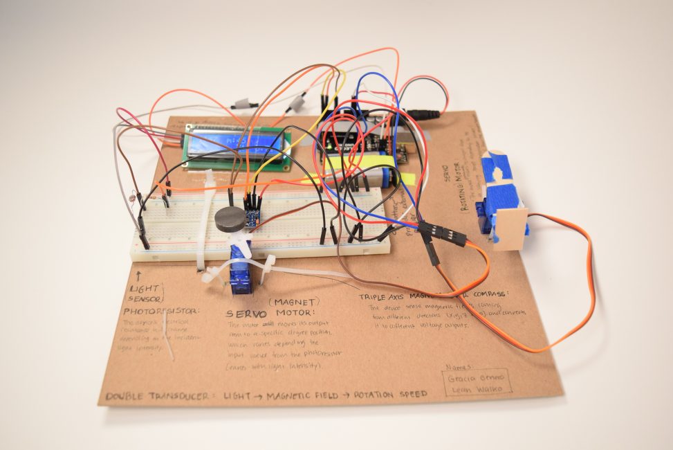
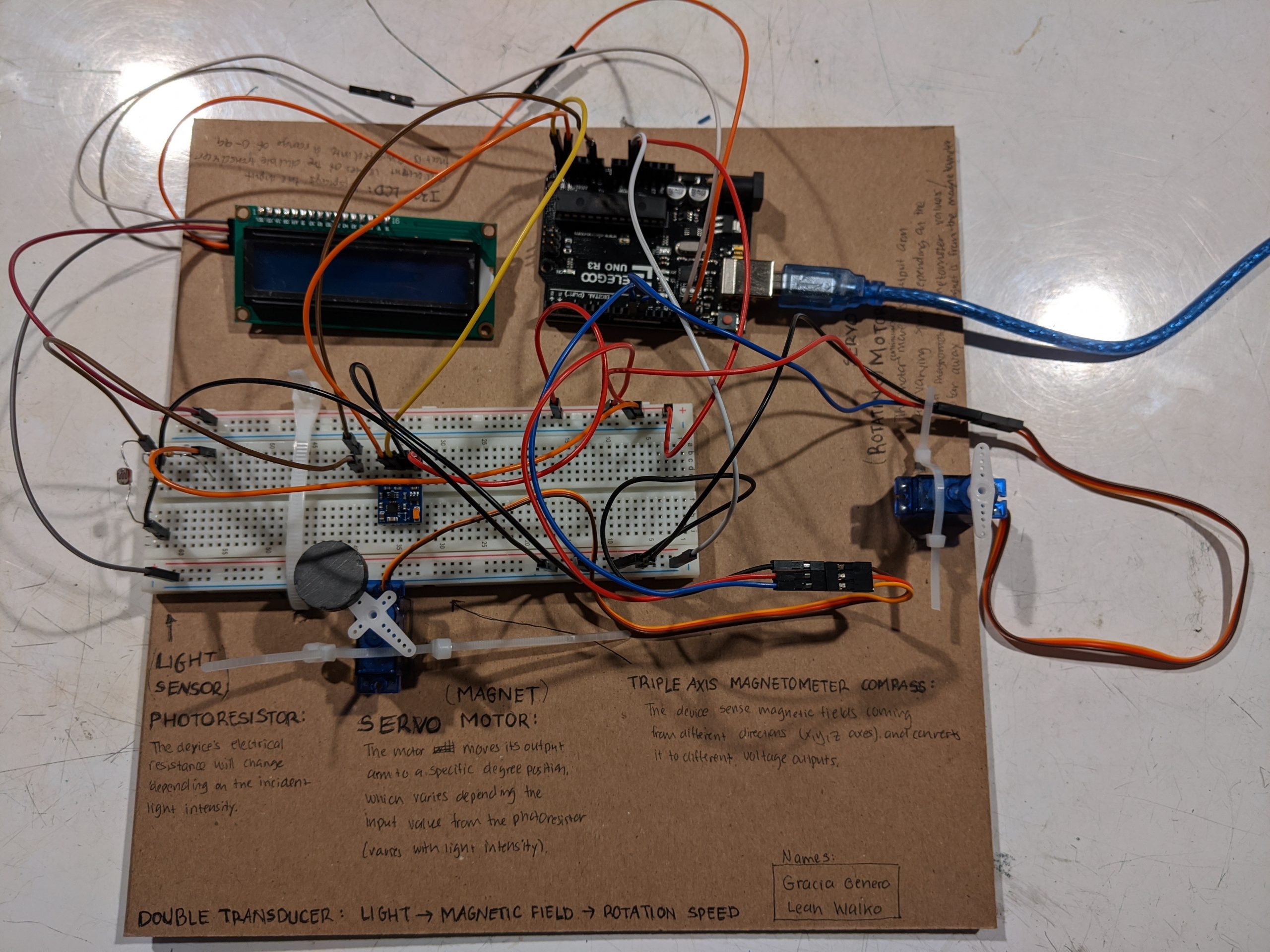
This double transducer is designed to convert light intensity to magnetic field strength, which in turn is converted to rotational speed. The photocell on the far left side of the stage measures surrounding light intensity. This value is then inputted into a 180-degree hobby servo motor that moves the attached magnet to different angle values. At higher light intensity, the magnet is at a lower position angle and is thus closer to the triple-axis magnetometer positioned in the middle of the breadboard. At lower light intensity, the magnet is positioned farther away from the compass. Only the magnetic field strength in the y-axis is measured because of the more linear correlation between the readings in the y-axis and the servo’s angle position. The magnetic field value then serves as an input for the 360-degree servo motor positioned at the far right of the stage. The rotational speed of the 360-degree servo motor increases as the magnet gets closer to the compass and the magnetic field strength is greater. Thus, increasing light intensity on the left side of the stage increases the rotational speed on the far right side.
Top view of Double Transducer: Light Intensity -> Magnetic Field -> Rotational Speed
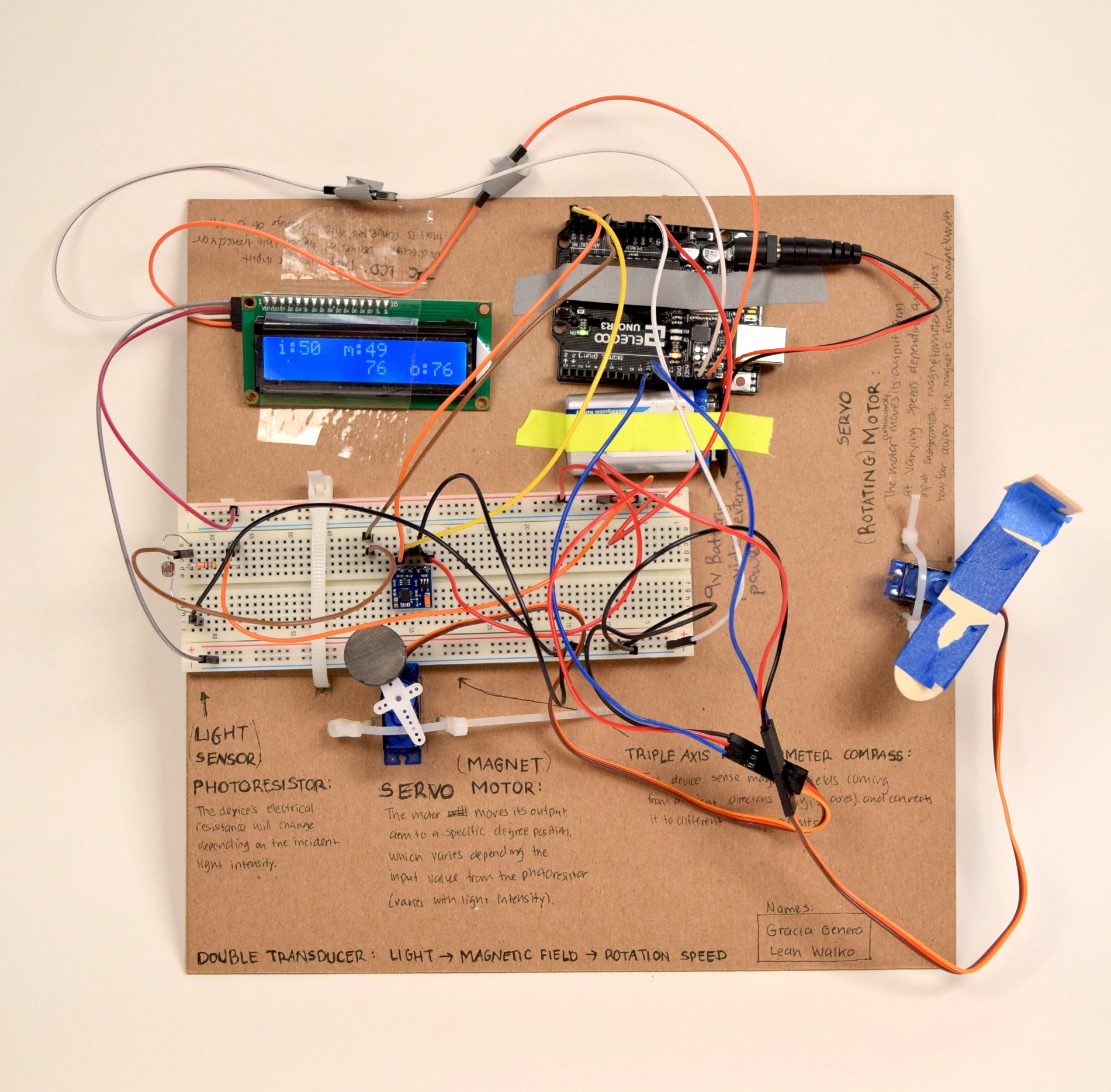
Light intensity input values are obtained using a photoresistor
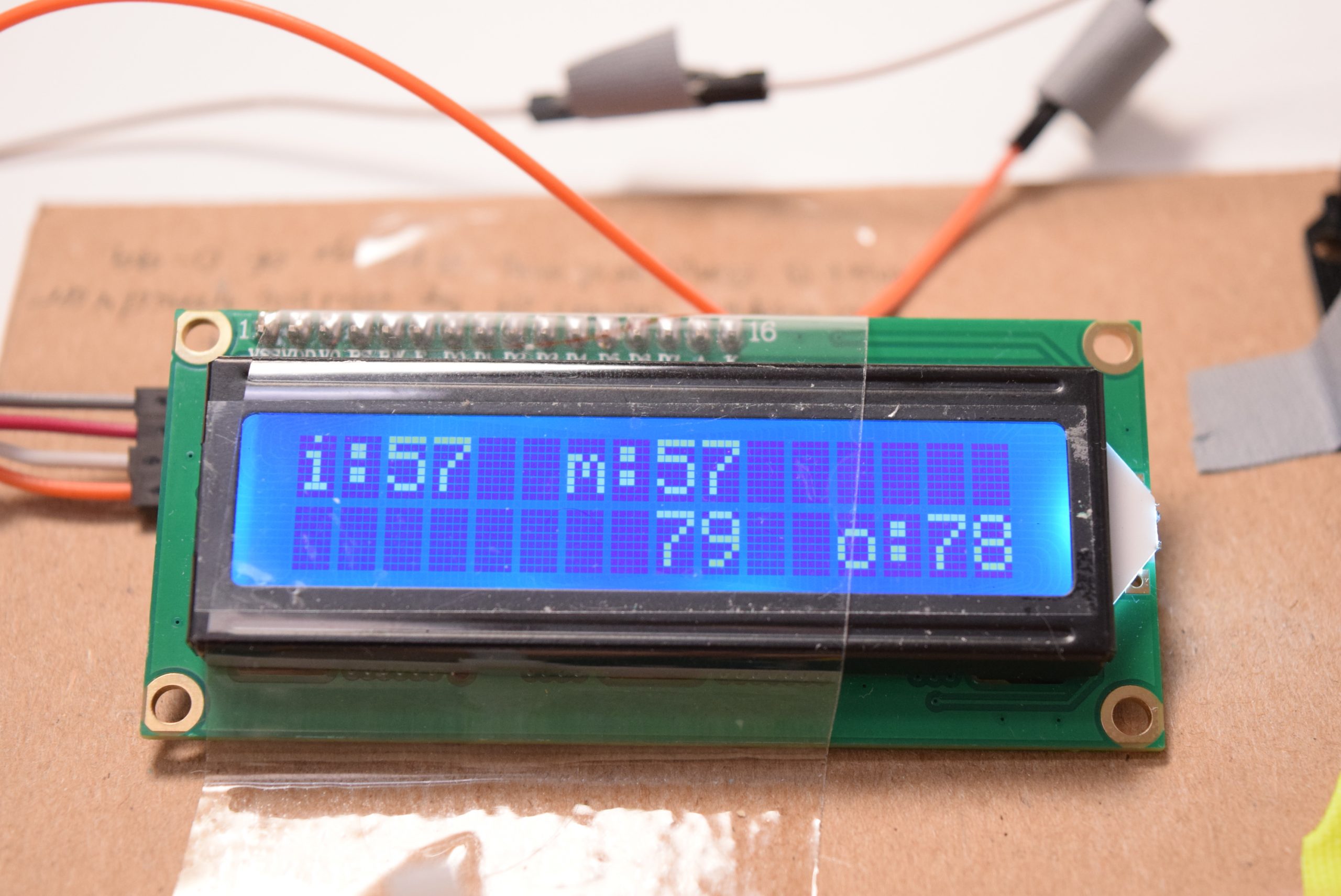
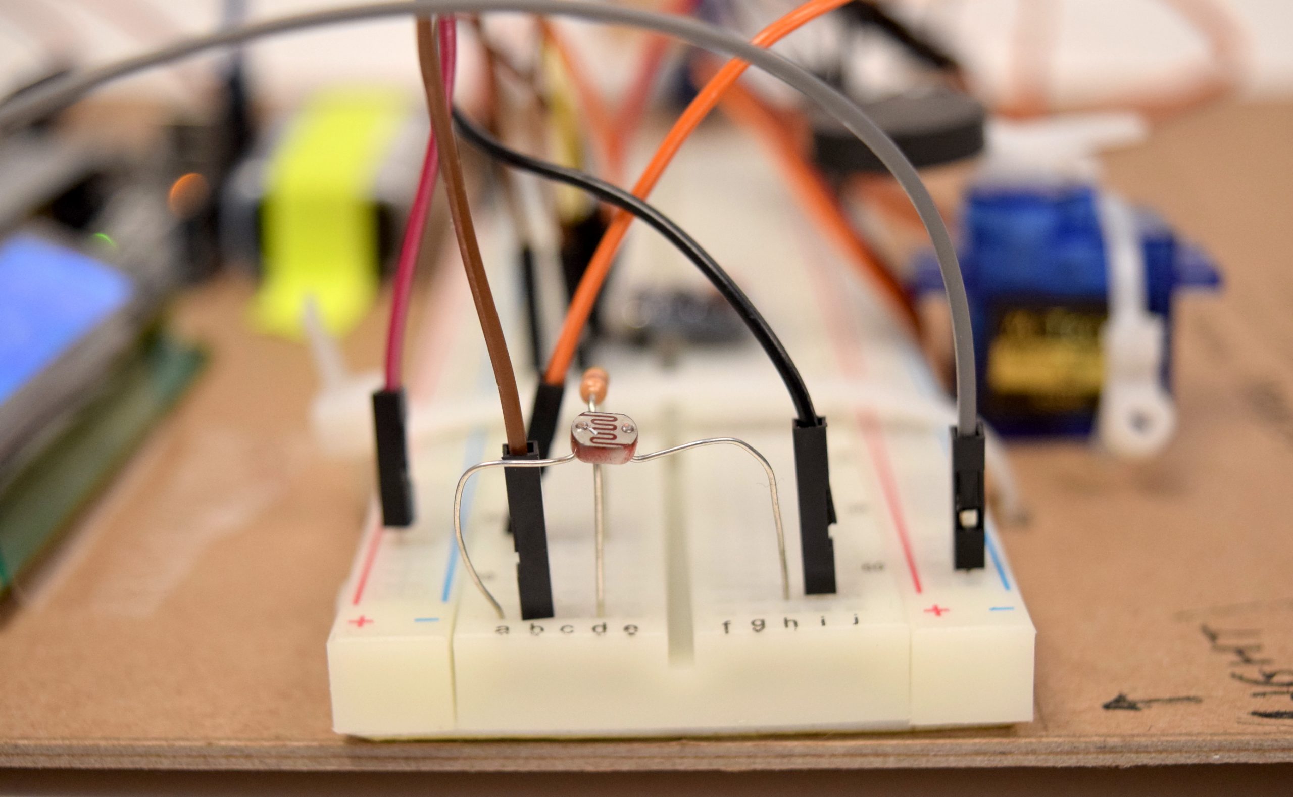
I2C LCD displays the input and output values of the double transducer
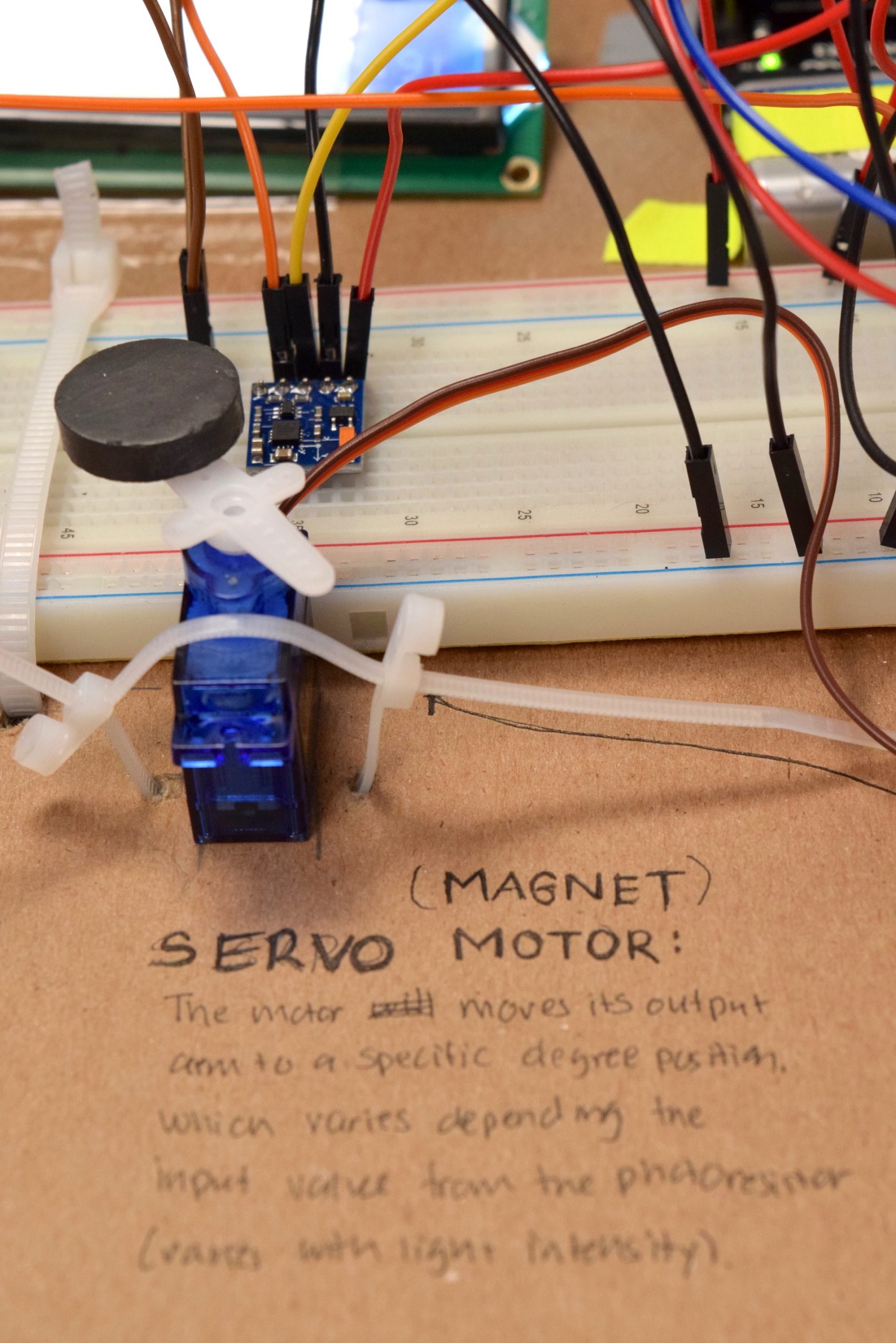
The servo with the magnet attached adjusts its position depending on light intensity. Position is measured using a triple-axis compass.
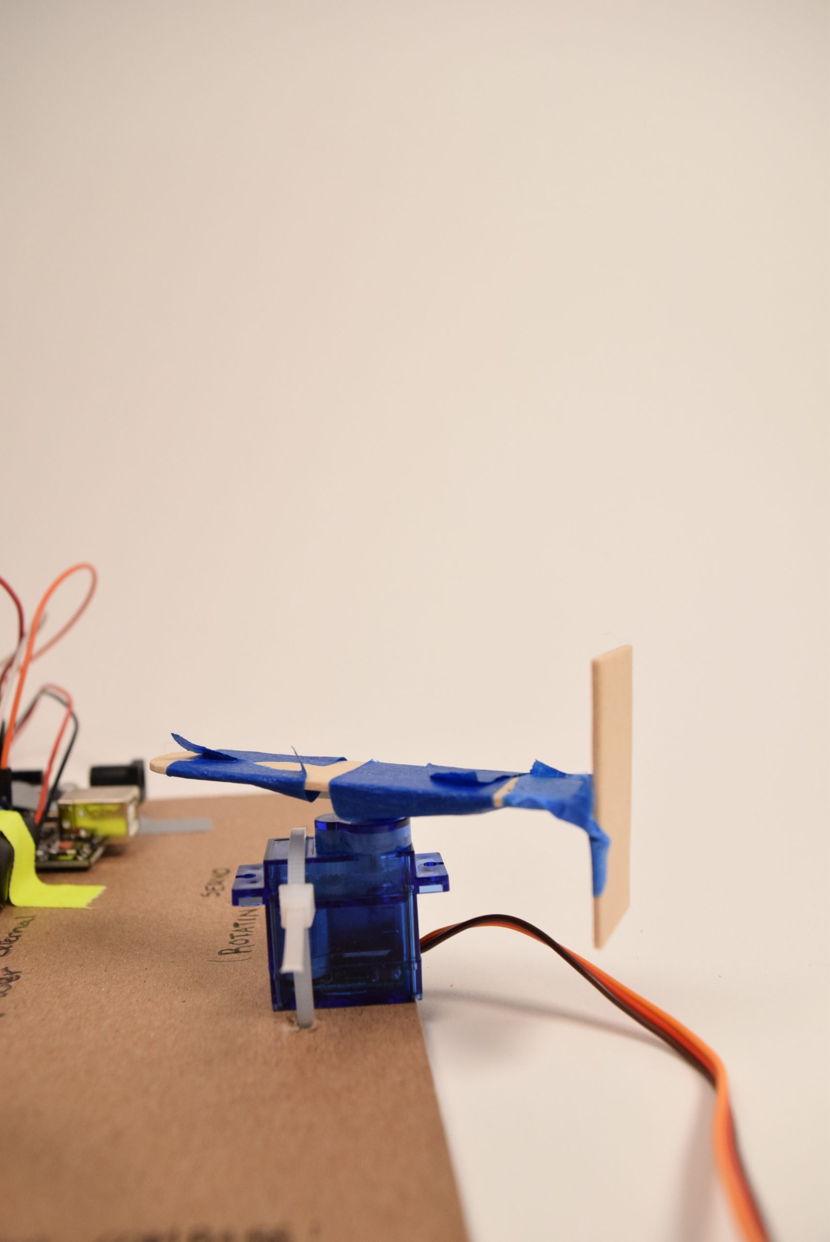
Position of the magnet varies the rotational speed of this 360 hobby servo.
Progress Images
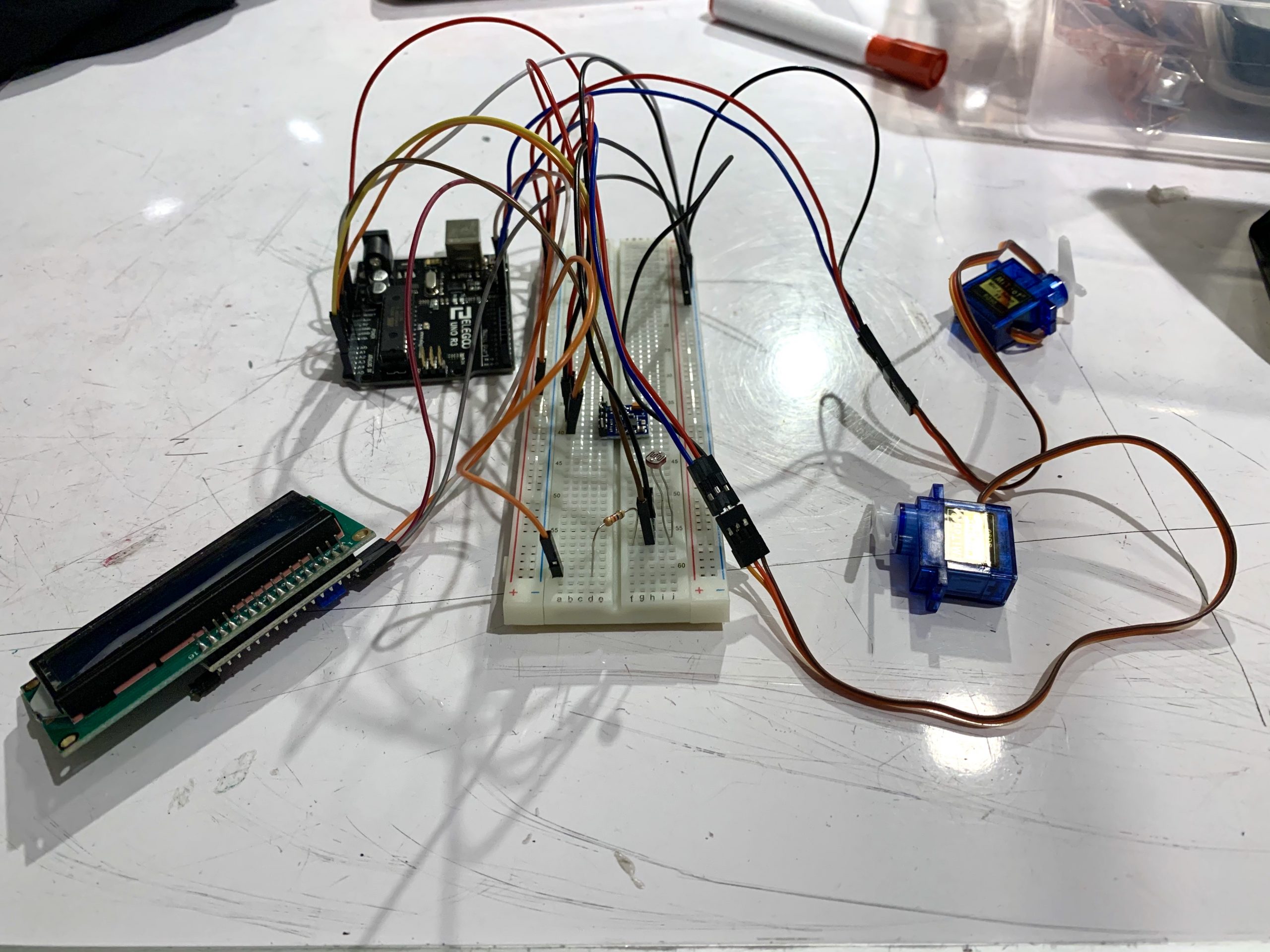
Project before components were positioned onto the board.
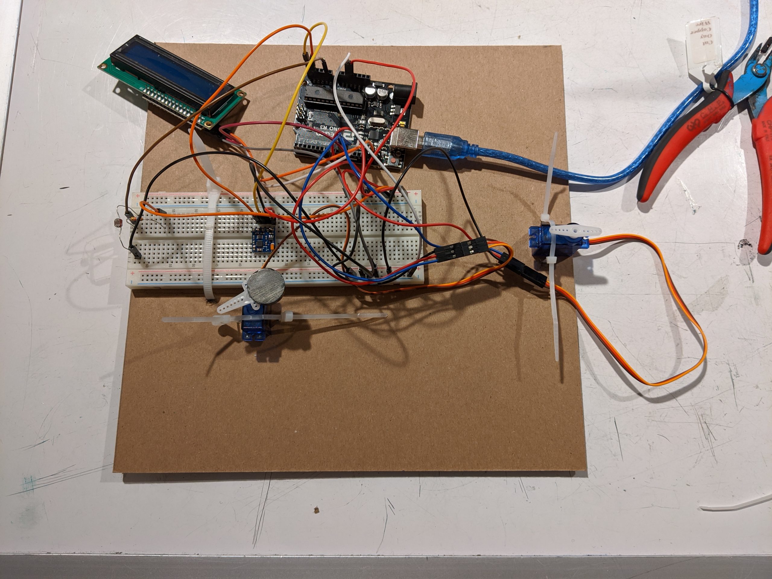
The first few components are zip tied to the board.
Wires are rearranged because the LCD was facing the wrong decision.
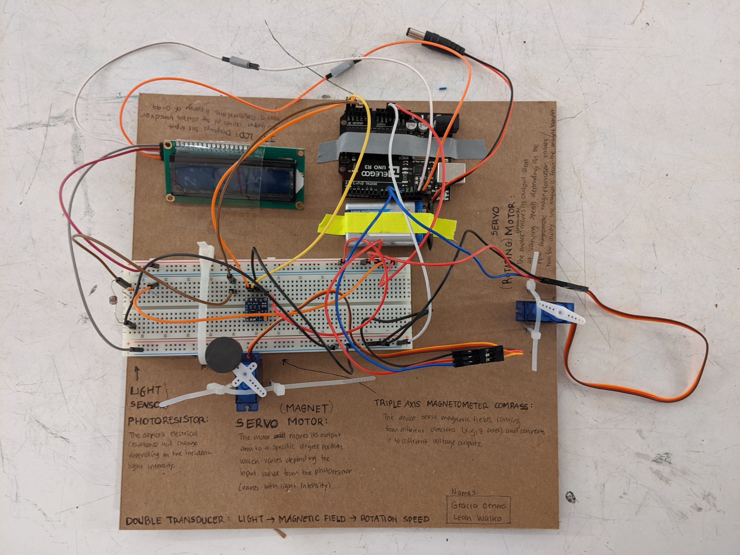
Battery is added so that it doesn’t rely on a laptop.
Discussion
Working with some of the components were easy, as we had worked with them before. We had no problems working with the photoresistor or servo motors. The challenge came from working with the magnetometer. Neither of us had ever worked with a compass before. Learning how it worked required research, and finding the right library was a difficult process. The library we initially found was unnecessarily complicated and only worked part of the time. It required a lot of fiddling with to determine what exactly was the problem. Figuring out how a new component worked and finding an appropriate library for the device was a new experience for us.
The project required a lot of tweaking to the maximum and minimum values in our code. Ensuring the inputs never went out of range and that the outputs were exactly what we wanted required us to constantly make slight edits and see how that affected the project. In addition to that, we had to make temporary code to test the range of values. Slight shifts in max and min values completely changed the rotation speed output, requiring us to carefully puzzle out the perfect range. The process gave us a new appreciation for constants in our code and valuable experience in testing a project.
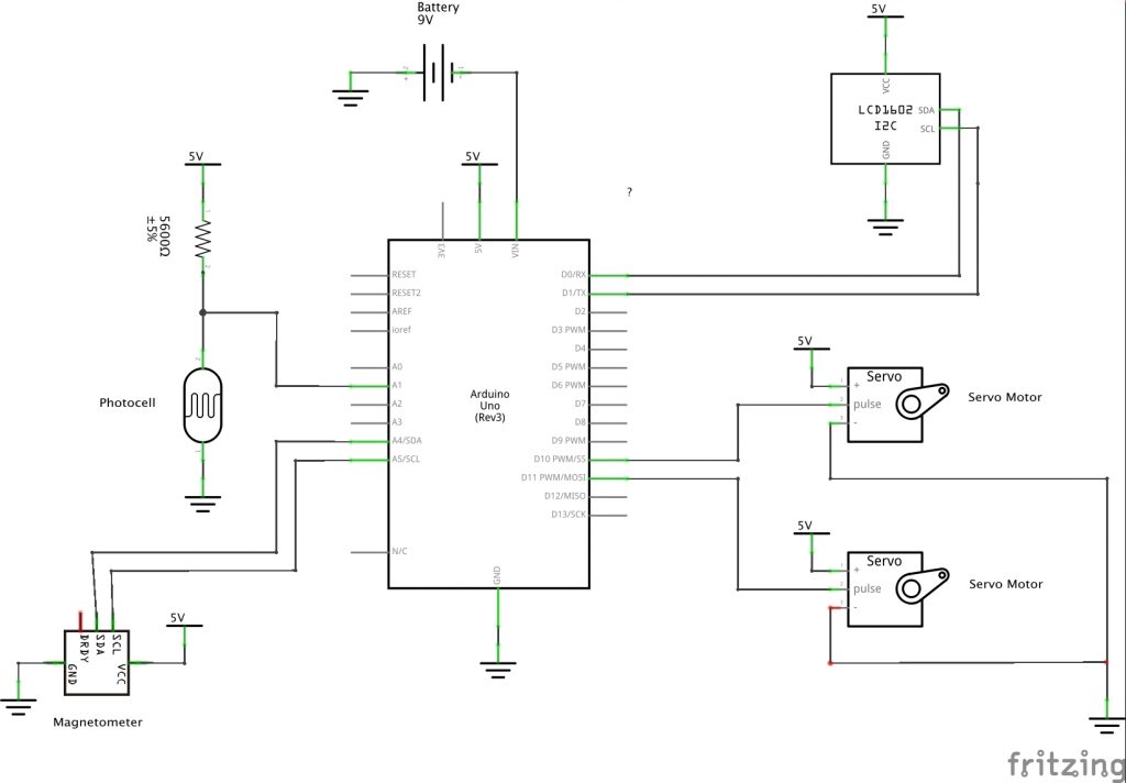
Schematic
Code
/*
   Project 1: Light Intensity to Rotation Speed
   Leah Walko
   Gracia Genero

   Description: A double transducer that turns light intensity into
   magnetic fields into rotation speed. A photoresistor picks up the
   intensity of the light. That value changes the location of a magnet.
   In turn, this affects the magnetic fields read by a compass, and based
   off that value a servo motor rotates at a faster or slower speed.

   Credit: QMC5883LCompass library creator, MRPrograms, for their xyz
   example code, and to the course's lectures and website.

   Pin mapping:

   pin   | mode   | description
   ------|--------|--------------------------------------------
   A1    | input  | photocell to measure light intensity
   A4    | input  | triple axis compass SDA input
   A5    | input  | triple axis compass SCL input
   10    | output | Servo motor that moves the magnet around
   11    | output | 360 degrees servo motor with variable rotation speed
   SCL   | output | I2C LCD
   SDA   | output | I2C LCD

*/

// servo library
#include <Servo.h>

// compass and lcd libraries
#include <Wire.h>
#include <LiquidCrystal_I2C.h>
#include <QMC5883LCompass.h>


// pin values
const int PHOTOPIN = A1;
const int MOTORMAGPIN = 10;
const int MOTORPIN = 11;

// range of possible values
const int ROTVAL_MAX = 89;
const int ROTVAL_MIN = 0;
const int MAGANGLE_MAX = 50;
const int MAGANGLE_MIN = 0;
const int LIGHT_MAX = 1023;
const int LIGHT_MIN = 0;
const int MAGVAL_MAX = 2700;
const int MAGVAL_MIN = -7500;

// timer for updating LCD
const int INTERVAL = 1000;
unsigned long timer = 0;

// LCD values
int screenInput = 0;
int screenMInput = 0;
int screenMOutput = 0;
int screenOutput = 0;

// compass values
int x;
int y;
int z;

// motor objects
Servo magnetMotor; // create a motor "object" called magnetMotor
Servo rotatingMotor; // create a motor "object" called rotatingMotor

// compass and LCD objects
QMC5883LCompass compass; // create a compass "object" called compass
LiquidCrystal_I2C screen(0x27, 16, 2); // create a LCD "object" called screen

void setup() {

  // setup the screen
  screen.init();
  screen.backlight(); // turn on the backlight to start
  screen.home(); // set cursor to home position
  screen.print("i:"); // print out the unchanging parts of the values
  screen.setCursor(6, 0);
  screen.print("m:");
  screen.setCursor(12, 1);
  screen.print("o:");
  delay(2000); // do nothing for 2 seconds

  // setup the input pin -> photocell
  pinMode(PHOTOPIN, INPUT);

  // Initializing compass
  compass.init();

  // setup the output -> motor moving the magnet + motor rotating
  magnetMotor.attach(MOTORMAGPIN);
  rotatingMotor.attach(MOTORPIN);
  rotatingMotor.write(90);

  Serial.begin(9600);

}

void loop() {

  // get info on light intensity
  int lightVal = analogRead(PHOTOPIN);

  // calculate the location of the magnet and move the motor to that angle
  int magAngle = map(lightVal, LIGHT_MIN, LIGHT_MAX, MAGANGLE_MIN, MAGANGLE_MAX);
  magnetMotor.write(magAngle);

  // get the compass value
  // Read compass values
  compass.read();
  // Return XYZ readings from the compass
  x = compass.getX();
  y = compass.getY();
  z = compass.getZ();

  // calculate magnetic value
  int magVal = y;

  // calculate rotation speed
  int rotateVal = map(magVal, MAGVAL_MIN, MAGVAL_MAX, ROTVAL_MIN, ROTVAL_MAX);

  // servo rotates at a speed of rotateVal (0 is faster, 90 is slower)
  rotatingMotor.write(rotateVal);

  // Update LCD screen values
  screenInput = map(lightVal, LIGHT_MIN, LIGHT_MAX, 0, 99);
  screenMInput = map(magAngle, MAGANGLE_MIN, MAGANGLE_MAX, 0, 99);
  screenMOutput = map(magVal, MAGVAL_MIN, MAGVAL_MAX, 0, 99);
  screenOutput = map(rotateVal, ROTVAL_MIN, ROTVAL_MAX, 0, 99);

  // Display updated LCD screen values only at specific time intervals
  if (millis() >= timer) {
    // print light val input
    screen.setCursor(2, 0);
    screen.print(screenInput);

    // print the magnetic field output value
    screen.setCursor(8, 0);
    screen.print(screenMInput);

    // print the magnetic field input value
    screen.setCursor(8, 1);
    screen.print(screenMOutput);

    // print the rotation speed output value
    screen.setCursor(14, 1);
    screen.print(screenOutput);

    // reset timer
    timer = millis() + INTERVAL;

    // serial output for testing purposes
    Serial.println((String)"X: " + x +
                         "; Y: " + y +
                         "; Z: " + z);

    Serial.println((String)"room brightness: " + lightVal +
                         "; magVal: " + magVal +
                         "; rotateVal: " + rotateVal +
                         "; magAngle: " + magAngle );
  }
}
Comments are closed.