For our final project, we interviewed someone who was disabled and designed a device that could help make their life easier. Our client was Jen, someone who had limited use in both her arms, but still wanted to help out with preparing food. However, without the help of her hands to orient and keep the produce in place, it was a very difficult task. As a result, we came together and designed a cutting board that could keep her fruits and vegetables in place as she cut, and could also turn to a different angle, to allow for dicing as well.
For more detail on the interview process and what we discussed, click this link!
What We Built
A cutting board that assists with keeping the produce in place when cutting and turns the board to ease the process of dicing fruits and vegetables.
Final Images
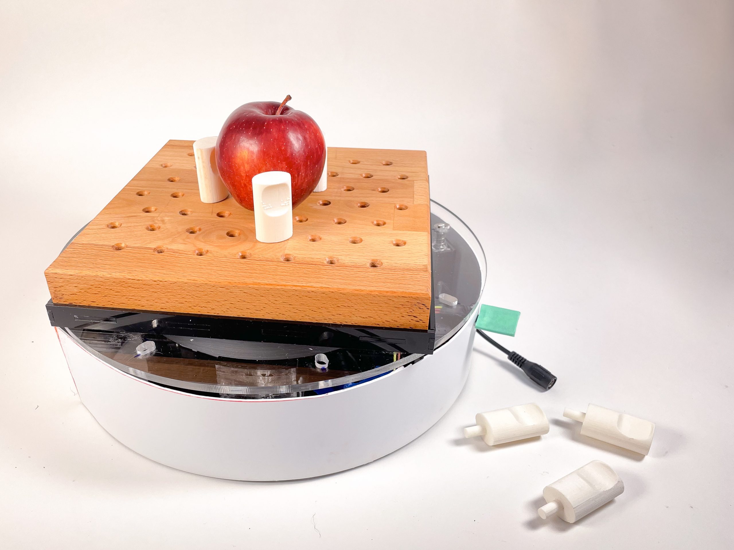
Overview of whole device
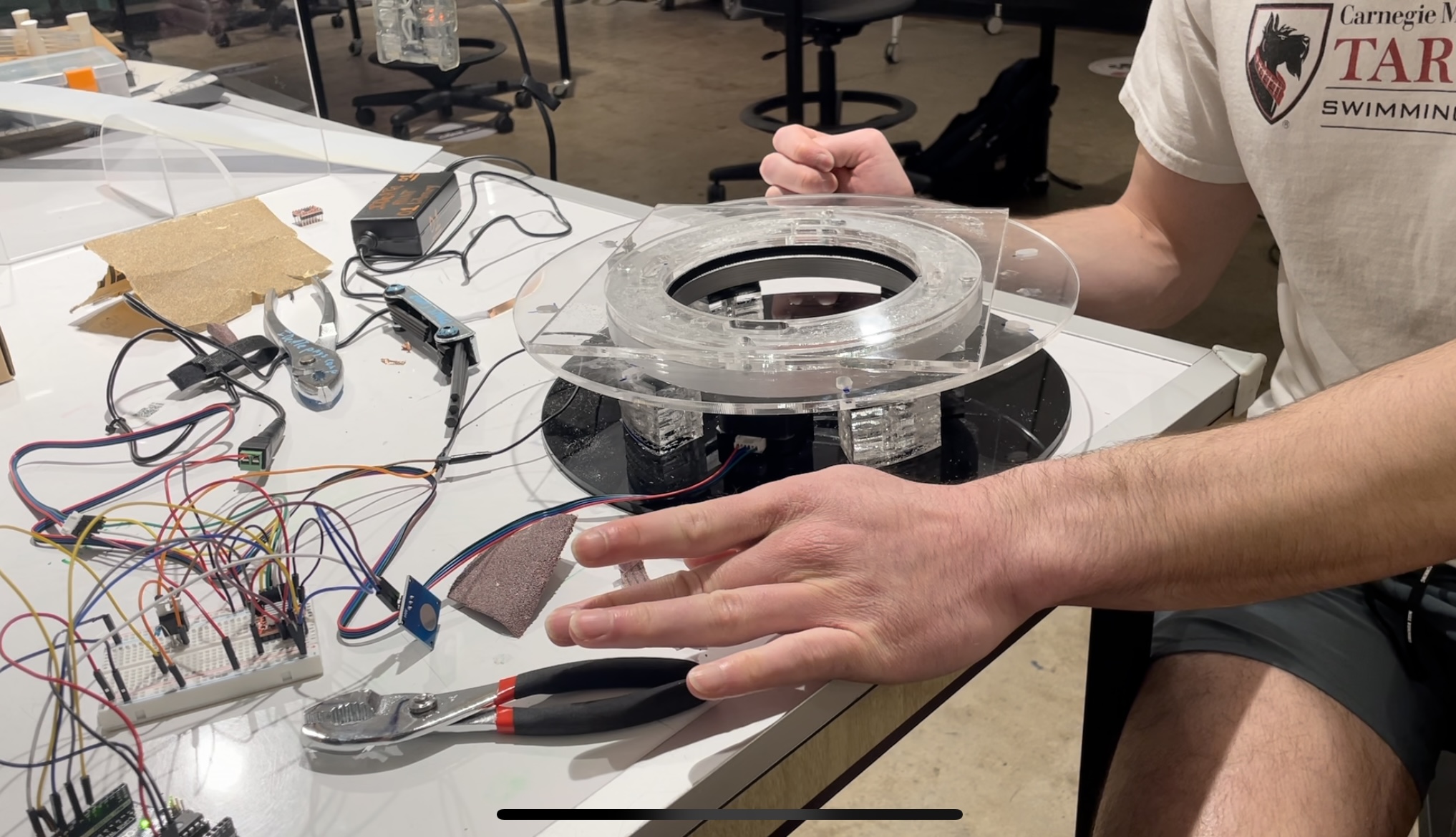
Device in use (due to the fact that we used a plastic knife, we are using our hand to activate the capacitive touch sensor)
Video of device working with knife tip
Video of how the braking system works with the solenoid
Detail Images
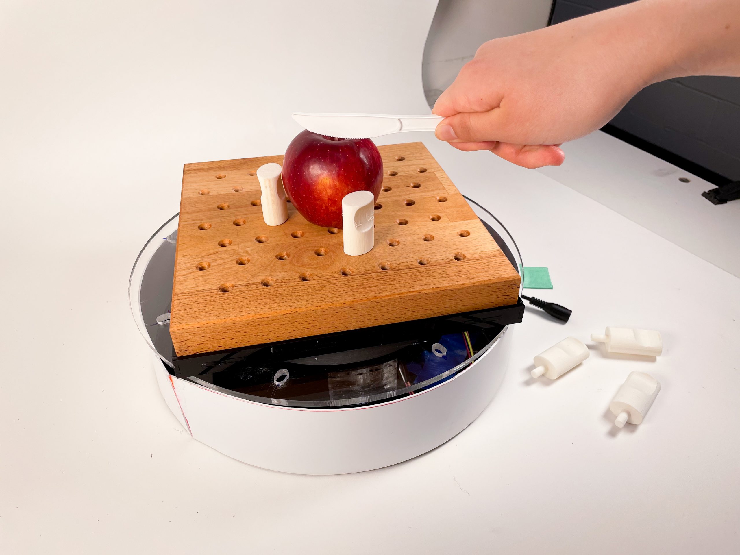
Using the device to cut fruit
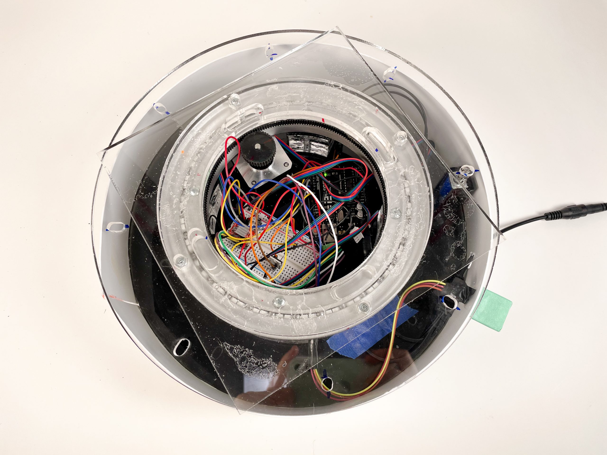
The inside mechanism of device

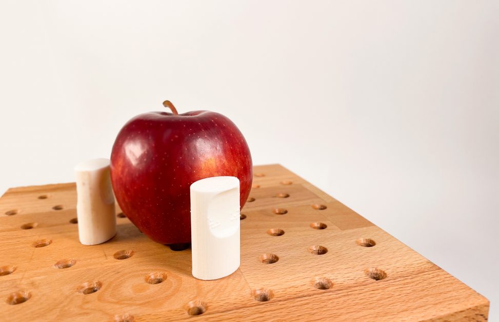
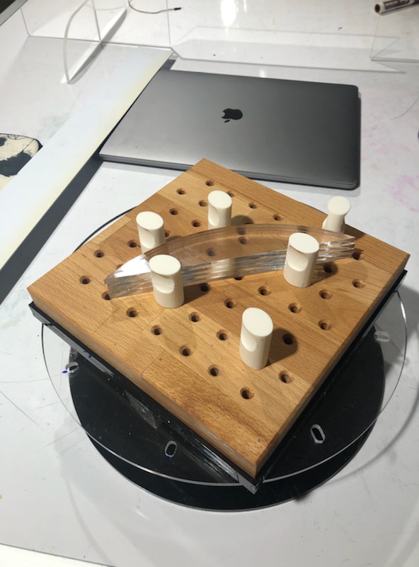
Pegs holding fruit in place
How the different pieces of the board come together. The black tray is there to catch excess food that fell through the holes.
Narrative Sketch
It’s dinner time! Maple got a new cutting board, and for the first time in years, Maple can comfortably help with food prep. In the past it was a struggle to cut just one vegetable since she can’t use her hands to hold them down. It definitely didn’t help that vegetables were naturally so round. She put a potato on the cutting board and positioned the pegs around it so that it was nice and secure. Then, with the knife in her mouth, she began to cut. *Slice!* She was able to cut the vegetable in a matter of seconds, when in the past it took her minutes. After she was done, she tapped her knife tip to the capacitive touch button, and the board turned 45 degrees. Today, she wanted to dice her potato, so she taped the button again, making a nice 90 degree angle, and she began to cut again. Chop, chop, and then she was done, with enough time to dice another potato. This device made food prep so much easier for Maple, and she’s really grateful for it.
Prototypes
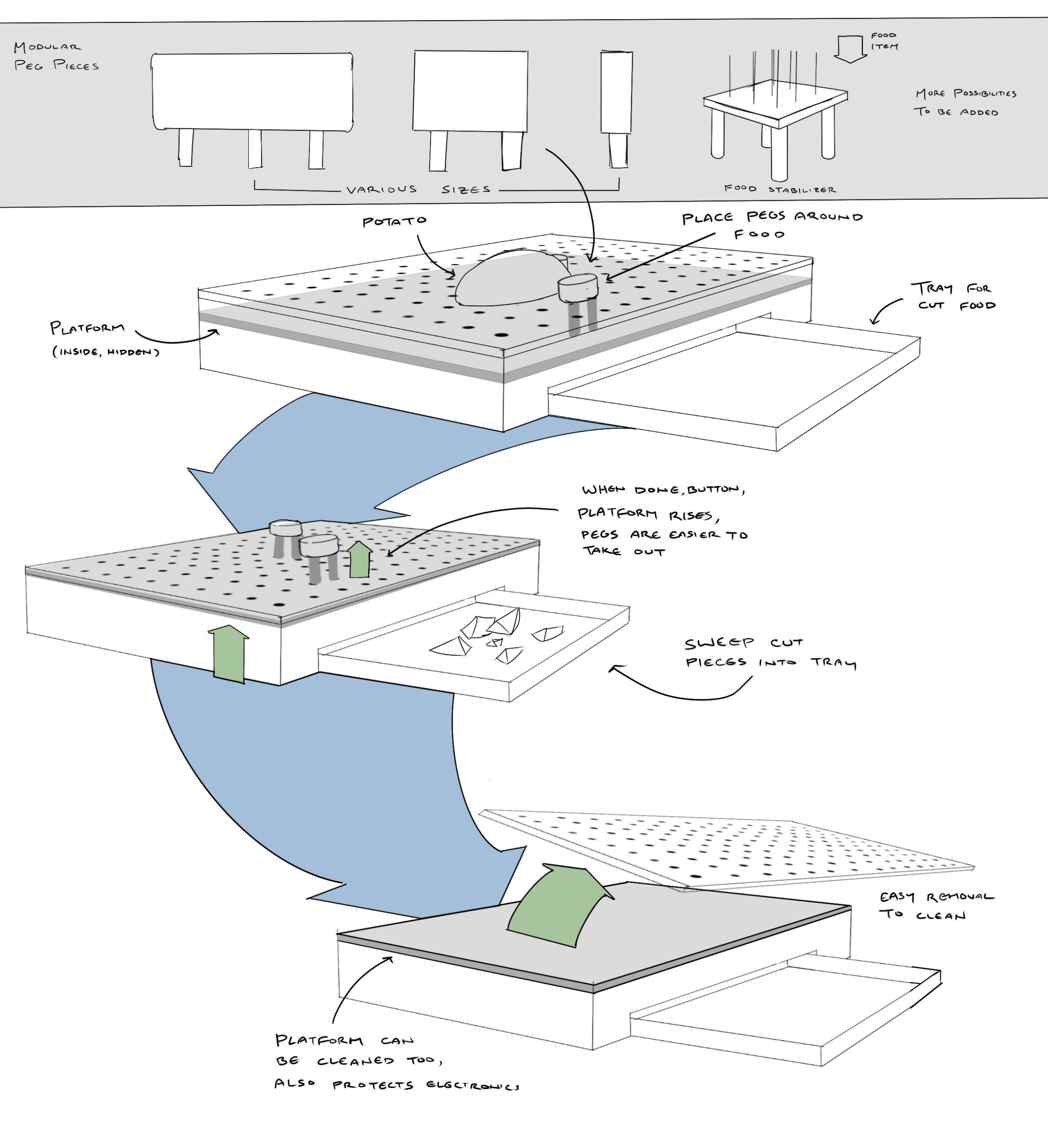
Prototype #1
- This prototype was made to address how all the different components of the device would come together, as well as to test out different peg types, and if the pegboard would actually be able to hold things still.
- For my first prototype, I made a cardboard model and created a housing for the mechanics, a space for a tray to catch excess, a variety of acrylic pegboards, and a variety of 3D printed pegs.
- 3 still images of prototype
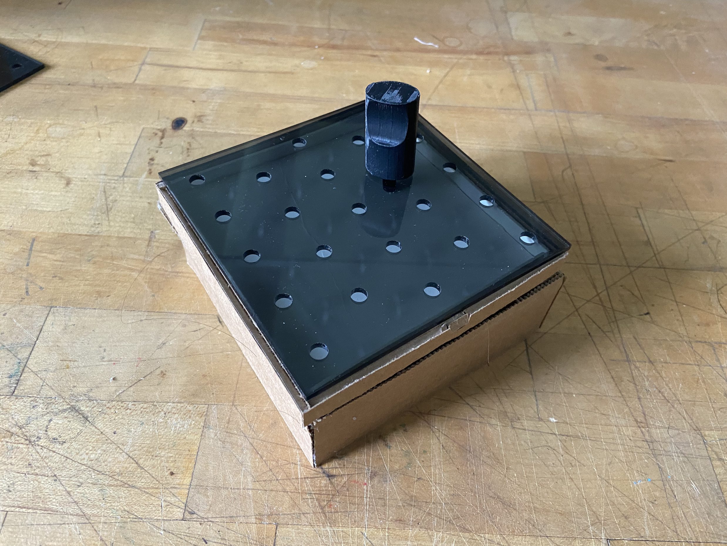
Overview photo of prototype
-
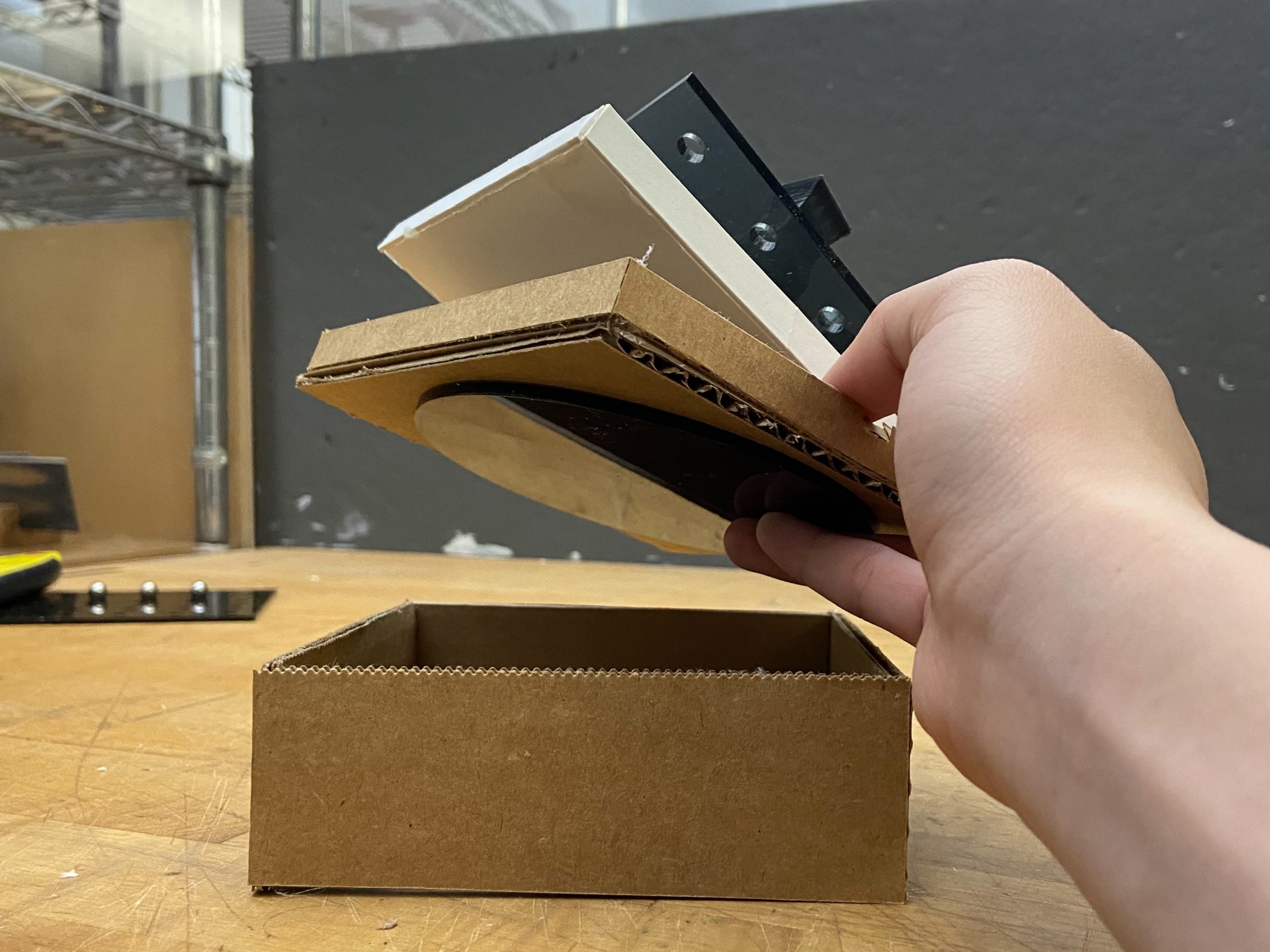
Explosion view of prototype
Trying out the prototype
- 1 moving image (video)
Video of the pieces and how the prototype would turn
- 3 images of prototype process
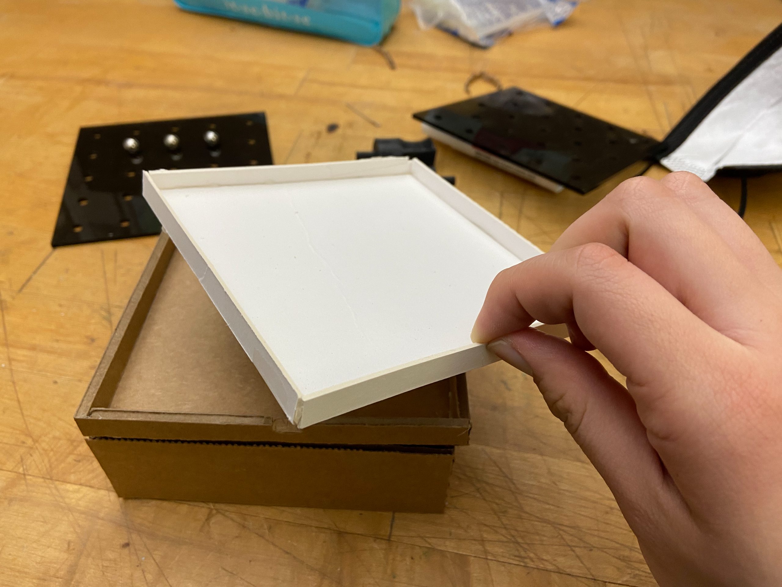
The making of the box and the tray
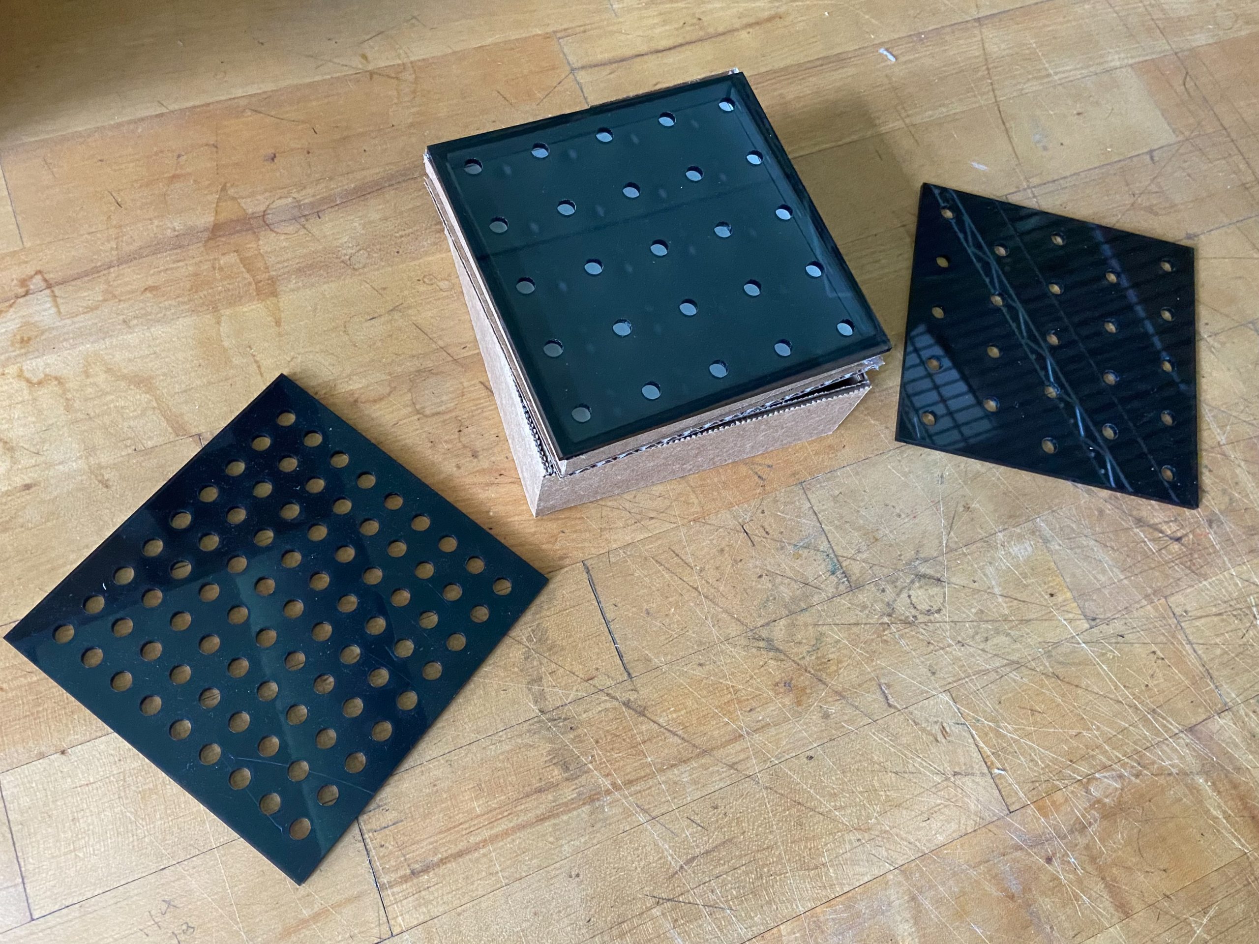
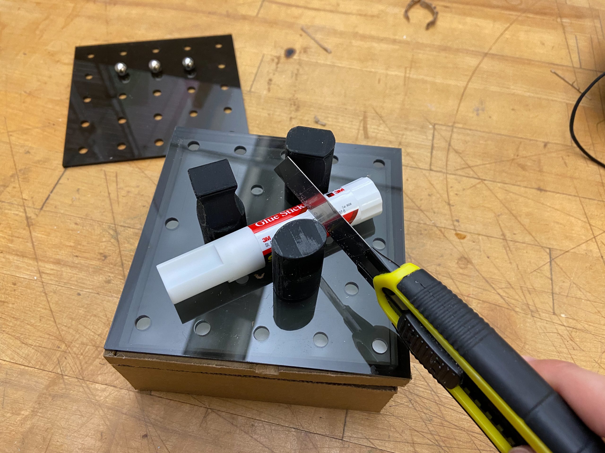
Trying out different pegboard layouts
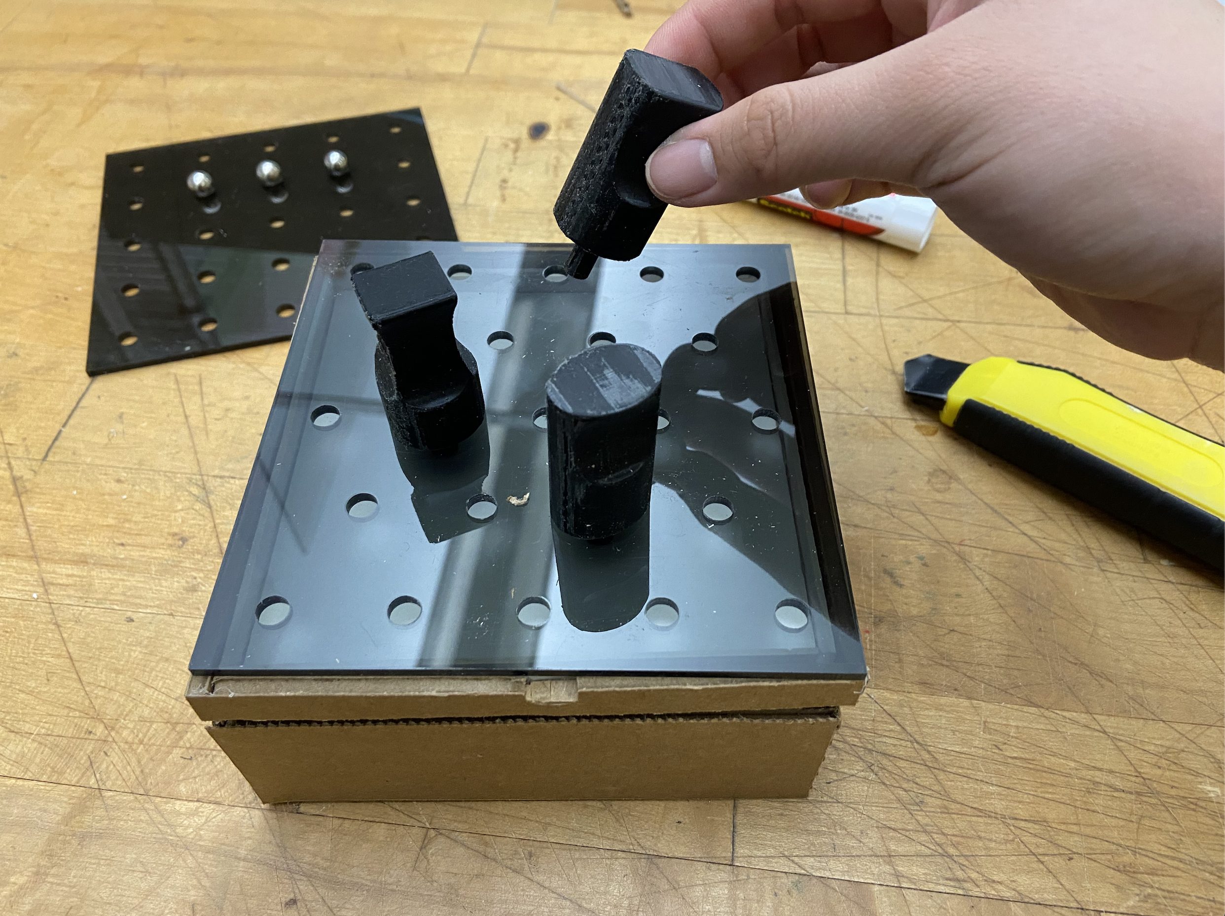
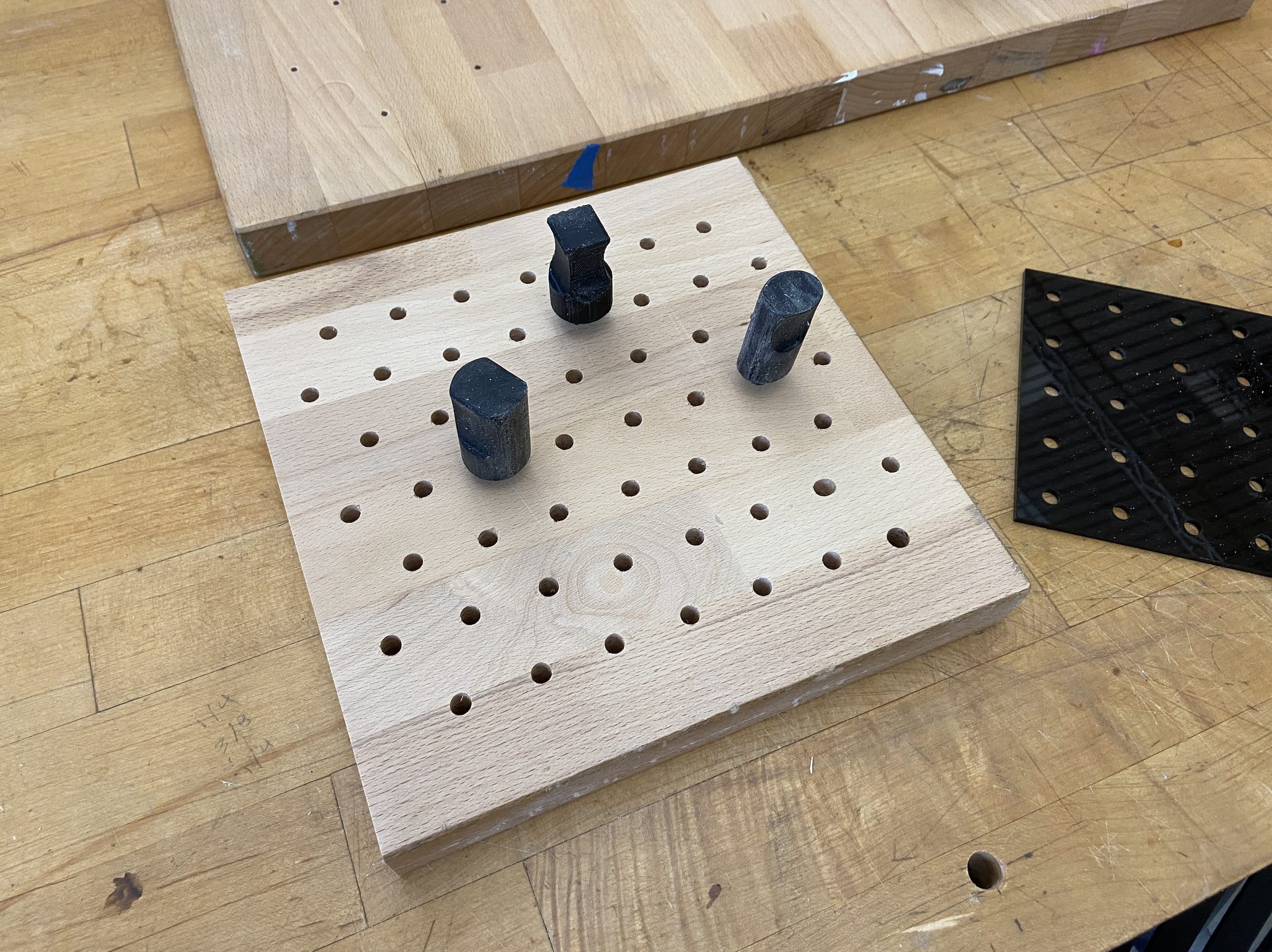
Testing out the pegs
- 200 words addressing what you learned
- From the prototyping process, I learned a couple of things. The first was that for the pegboard layouts, our first design was too compacted, which would have resulted in really small pegs, which would’ve been a choking hazard. As a result, we switched to a wider spacing, but in this design, we found the grid design to be too constraining, so we opted for a scattered peg design, more fitting for different food sizes. Same goes for the elliptical pegs. We started off with 3 different peg designs, and though testing, found that the elliptical design was the most adaptable to different sized objects. Our feedback was pretty positive, but some things that we improved on was limiting the amount of pieces there were. We merged the tray and the piece connecting the pegboard to the mechanism together, making less pieces to keep track of. Some feedback we ignored was the issue about cleaning the pegboard. However, Jen herself didn’t really find an issue with it, and liked the peg design overall, so we continued on with that design. Some surprises I encountered during the prototyping process was just how difficult tolerancing was, especially with wood. The would would expand when it met moisture, messing with how the pegs fit in the holes. Also, the direction you 3D print is important. We printed our pegs vertically at first, making them really prone to snapping. We had to orient it differently to fix that issue.
Prototype #2
- This prototype was made to address the rotation of the cutting board. Specifically, we were trying to answer the question of how are we going to rotate the cutting board in a reliable manner?
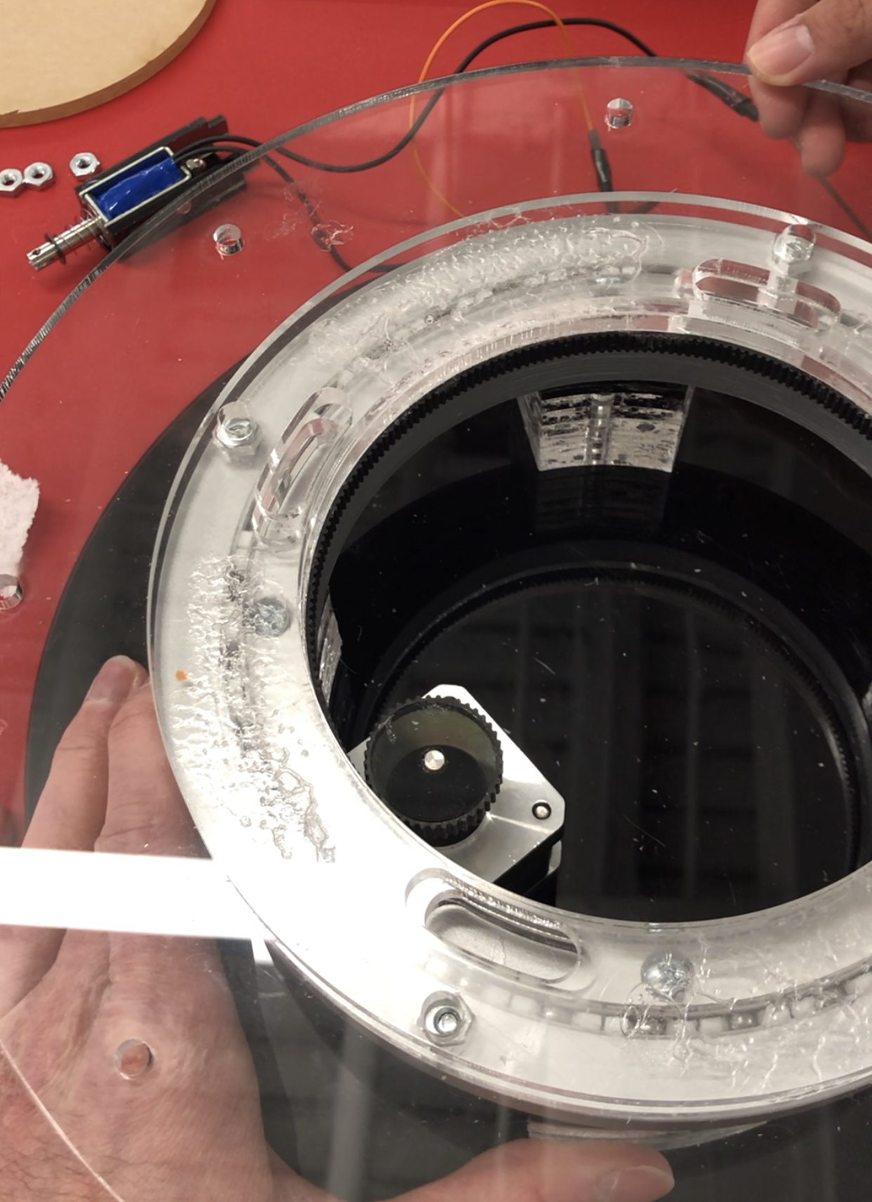
- The mechanical prototype uses metal balls to allow the top portion to rotate independently from the bottom portion. The metal balls are held in place by a circular path constructed from acrylic. When the user or motor turns the top portion, the cutting board on top rotates while the bottom portion stands stationary.
- 3 still images of prototype
Demonstration of turntable bearing and friction drive prototype
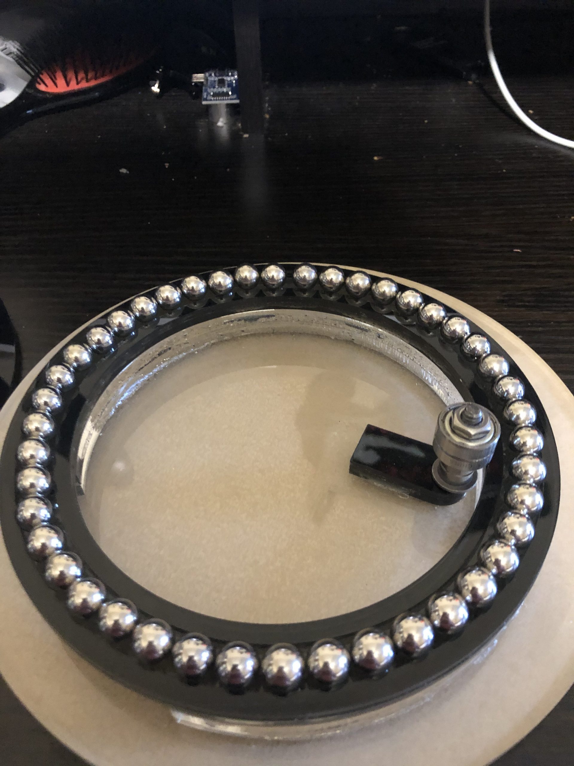
Ball bearing track to hold ball bearings in place
Slot for electronic wiring to be fed through to the outer shell
- 1 moving image (video)
- 3 images of prototype process
Initial sketch of rotation mechanism with friction drive
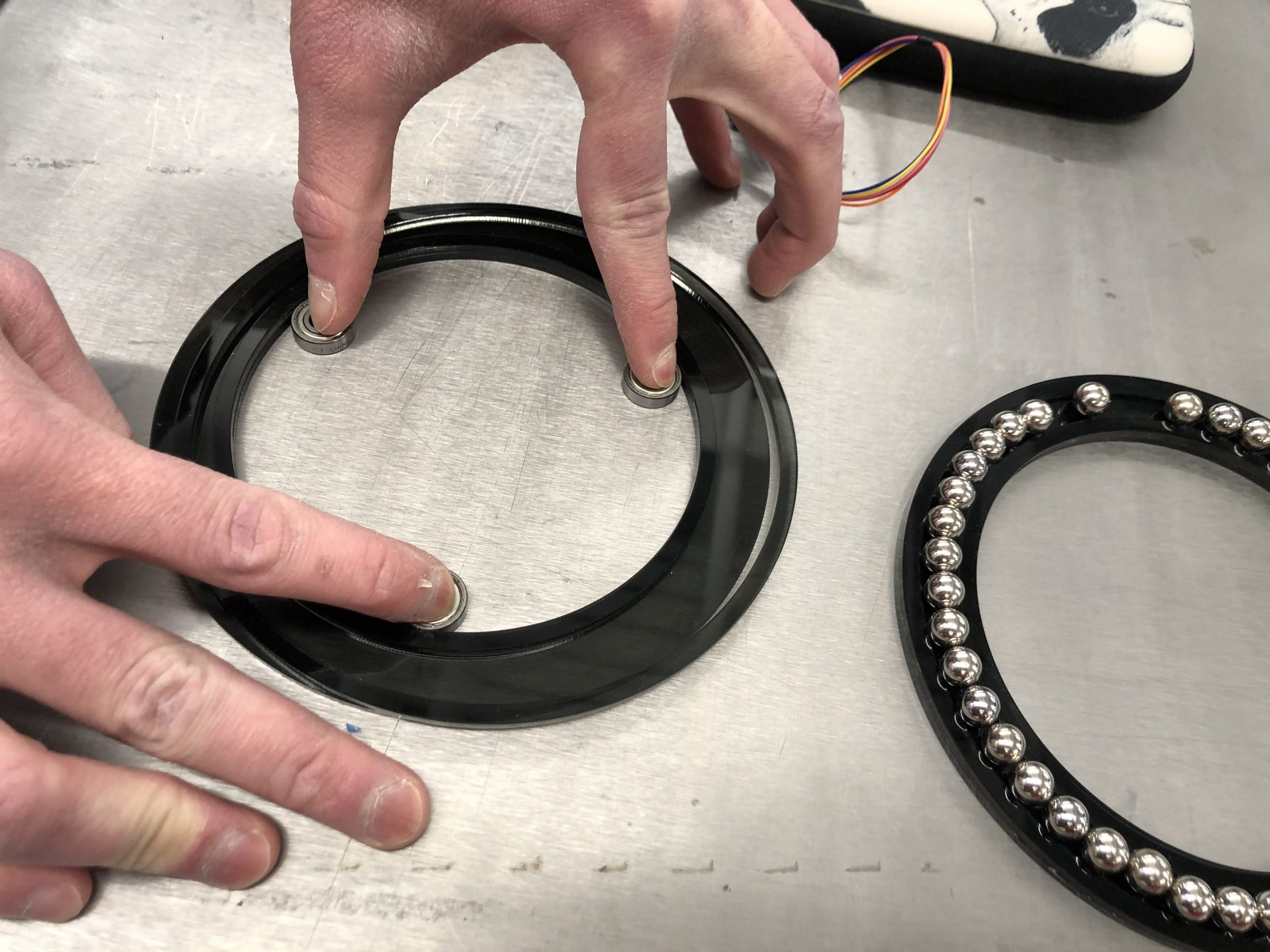
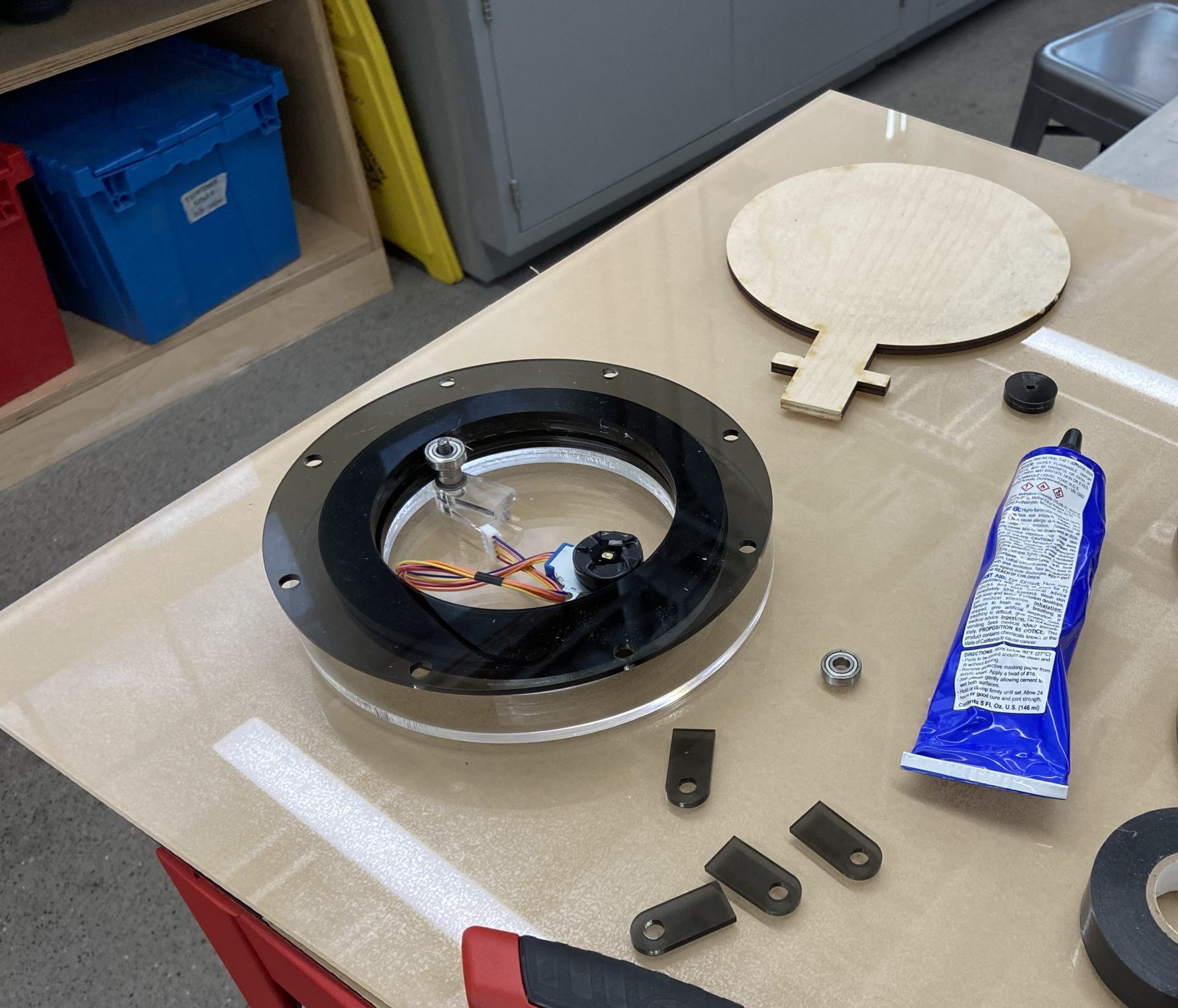
Gluing technique used to center the ball bearing tracks while gluing them in place
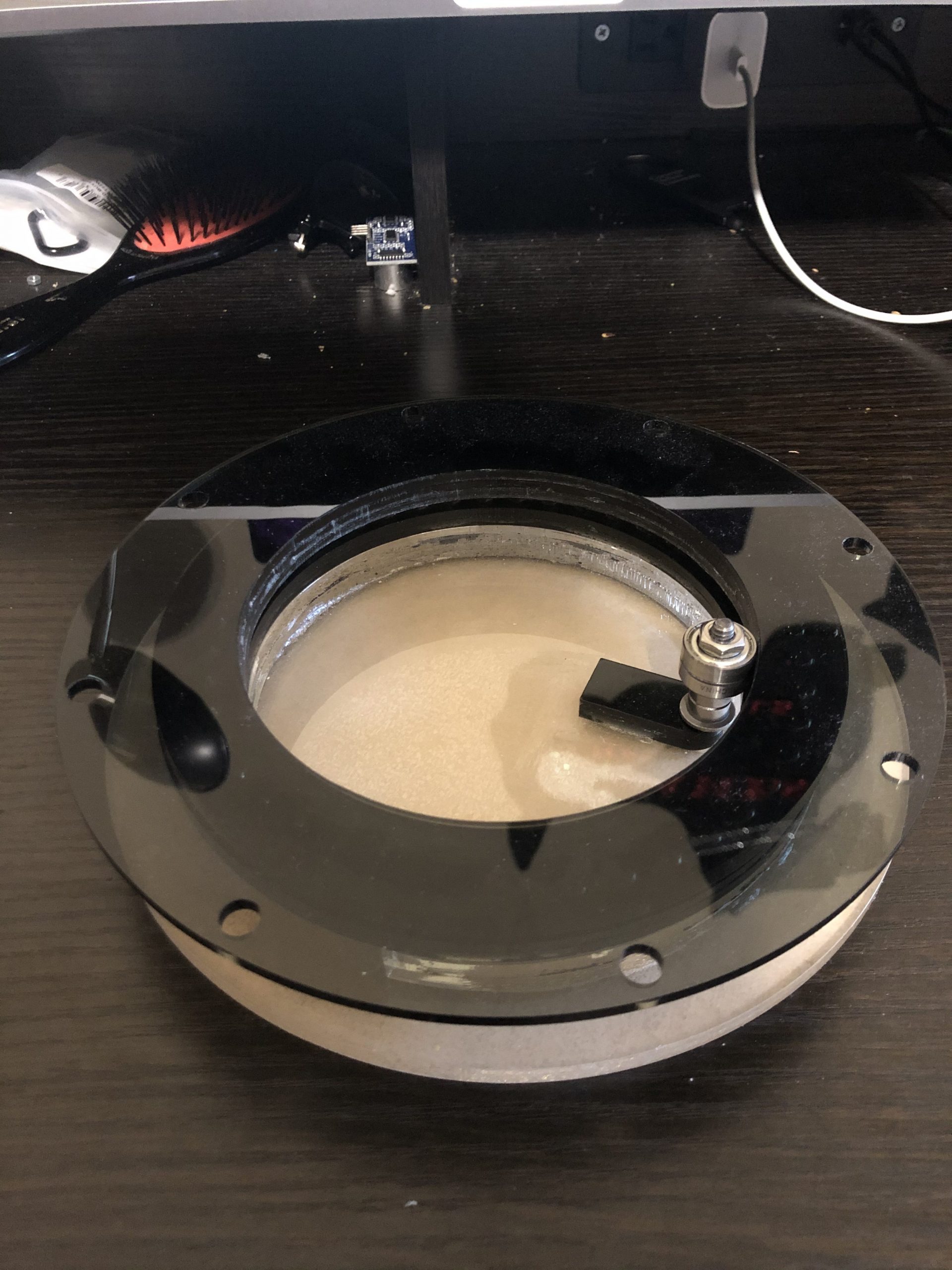
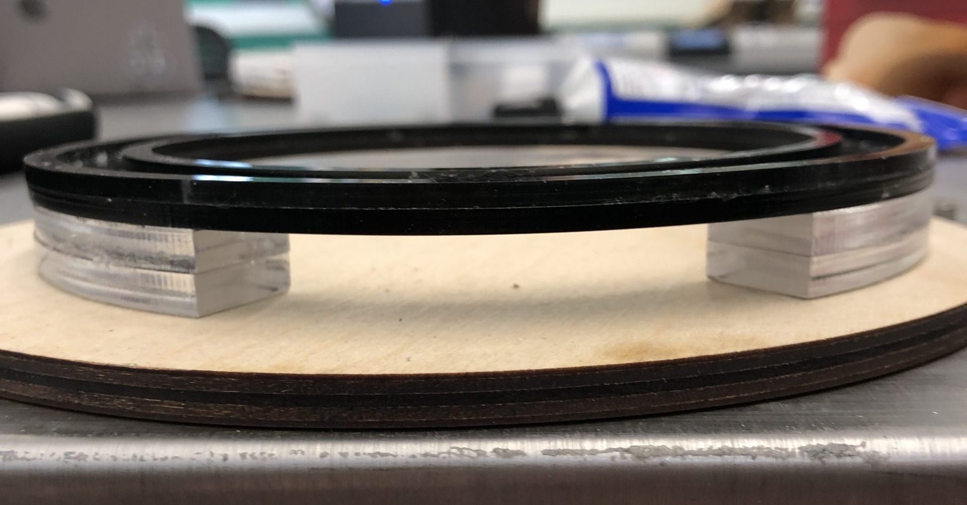
Image of turntable bearing by itself without stepper motor and friction drive
- 200 words addressing what you learned
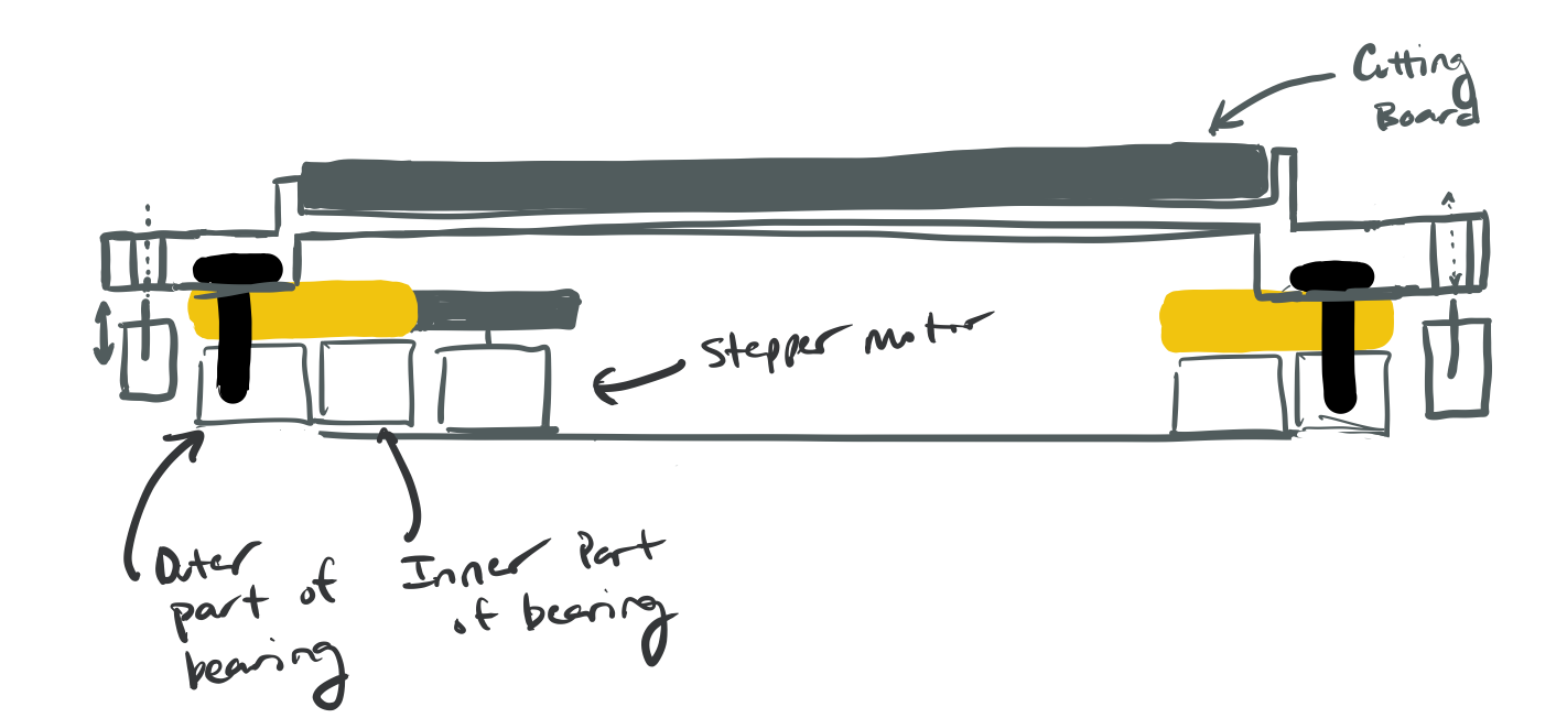
Our goal with the mechanical prototype was to determine how we would get the cutting board to rotate and allow the user to cut from many different angles. The scaled bearing design we came up with worked well allowing us to rotate the outer bearing without the inner bearing. The scaled version was able to rotate with little friction and stand up to the downward pressures of cutting. The friction drive, however, did not work as intended. We had initially thought that the friction between electrical tape and acrylic would be enough to move the inner part of the bearing with little trouble. Surprisingly, we could not get enough friction instead seeing a lot of slipping between the motor wheel and the inner part of the bearing. Based on this result, we decided to move forward with a gear design instead to improve the reliability of the force transfer from the stepper motor to rotation of the cutting board.
When demonstrated to Jen for the first time, the rotation concept and implementation was enthusiastically approved. She loved the idea of being able to rotate the vegetable so that she did not have to keep unpinning it and re-pinning it. She did, however, request a food bucket to swipe cut vegetables into in order to declutter the cutting board but this feedback was not implemented into the final product because it was outside the scope of the project.
Prototype #3
- This prototype was built to answer Arduino and electronic questions: What should we use as a break for the rotation device? Do we need more torque for the electronic that rotates the device?
- This prototype consists of two parts. The first is a stepper motor that rotates a set amount when activated by a touch sensor. The second part is a small solenoid (an electronic with a small rod that can move back and forth) which is also activated by the touch sensor. When the touch sensor is touched, the stepper motor will rotate 45 degrees and the solenoid will activate (kind of like releasing a break) and when the stepper motor finishes, the solenoid will release (kind of like activating a break).
- 3 still images of prototype
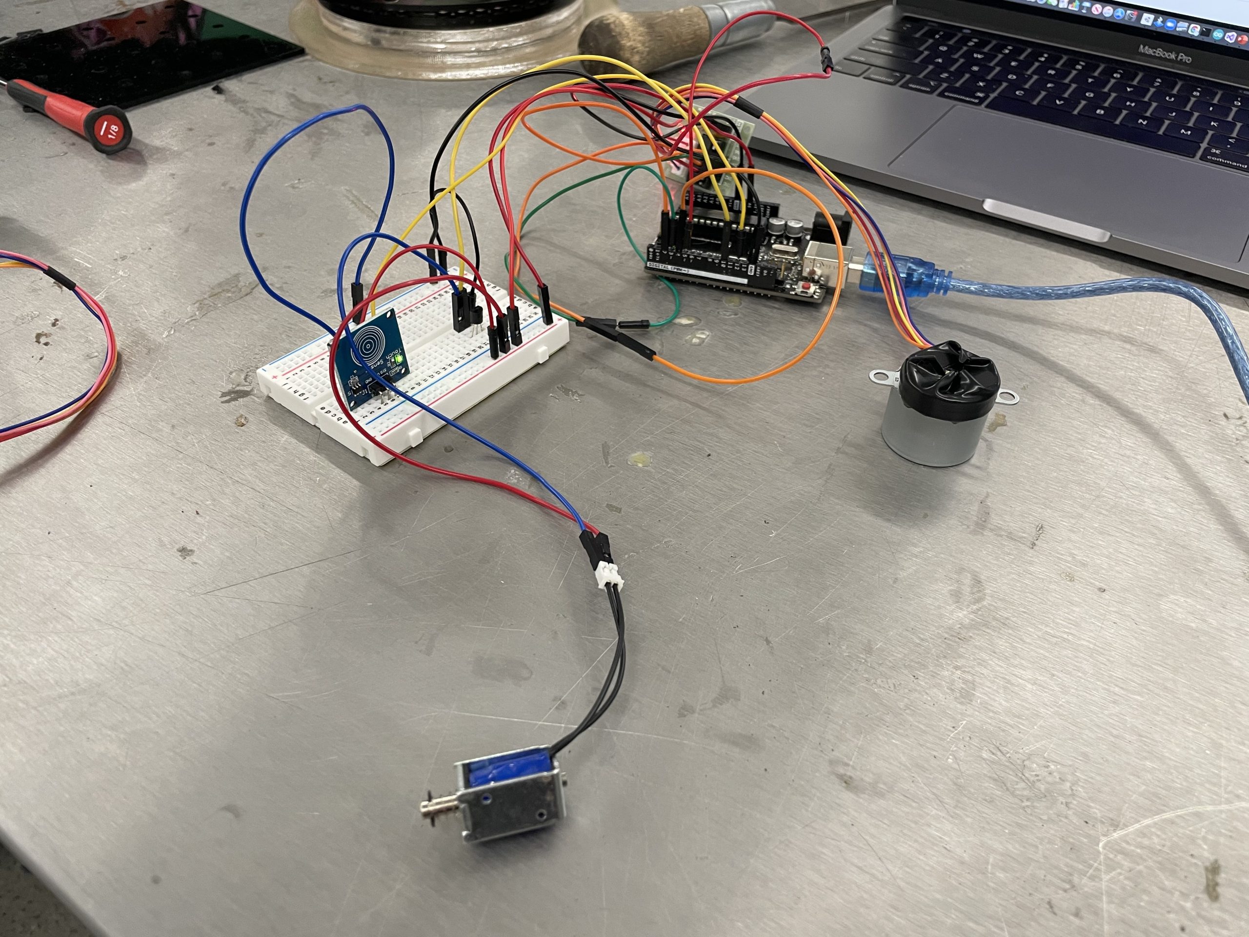
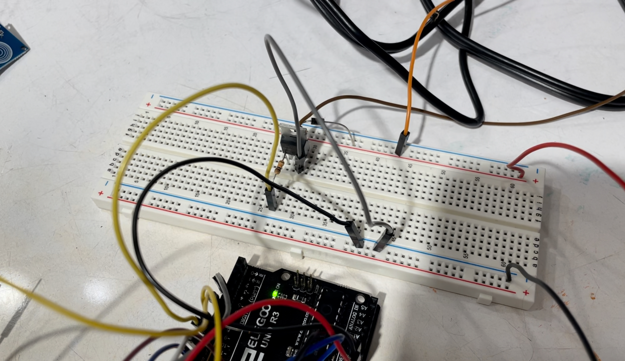
Overall view of prototype. Includes touch sensor, small solenoid, and a small stepper motor.
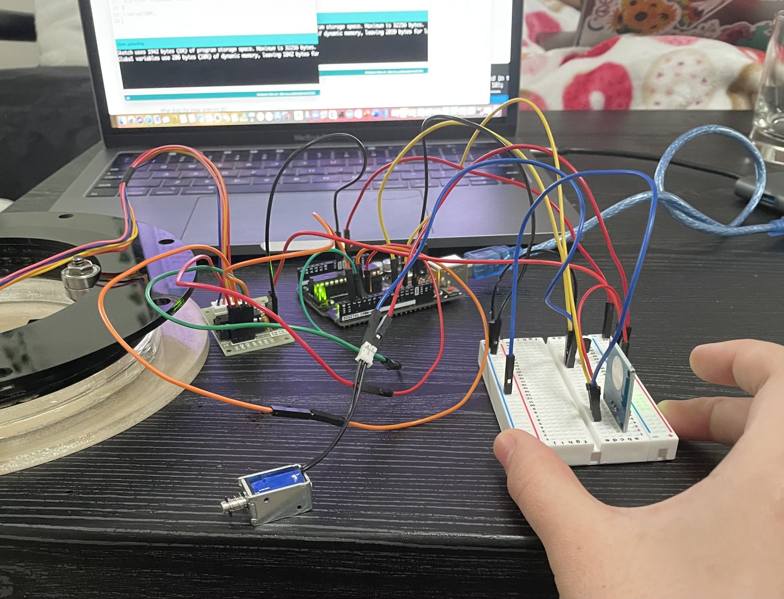
Everything activated by the touch sensor. Solenoid activates and the stepper motor rotates.
Experimenting with multiple touch sensors and attempting to make the motor rotate both ways.
- 1 moving image (video)
- 3 images of prototype process
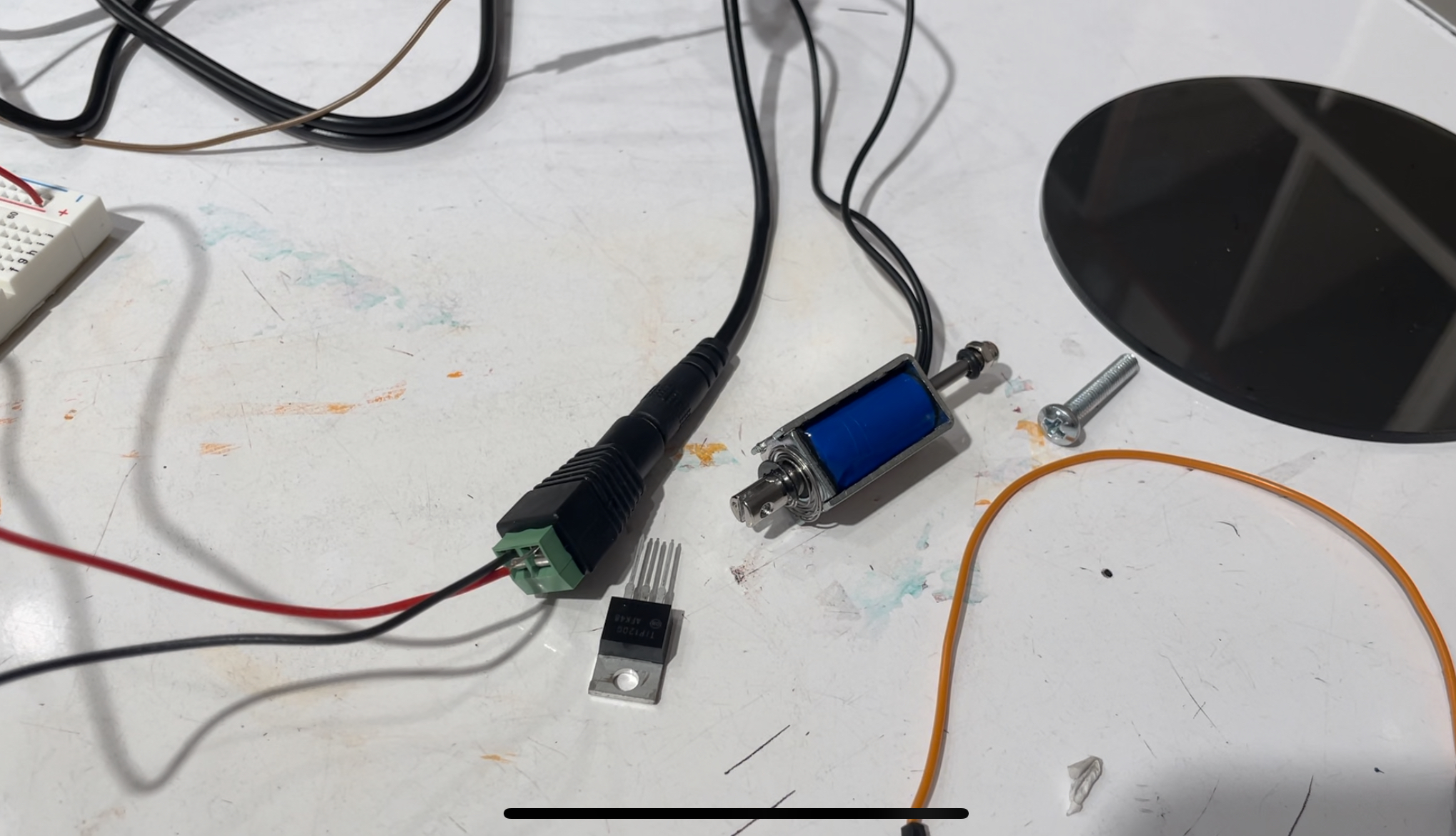
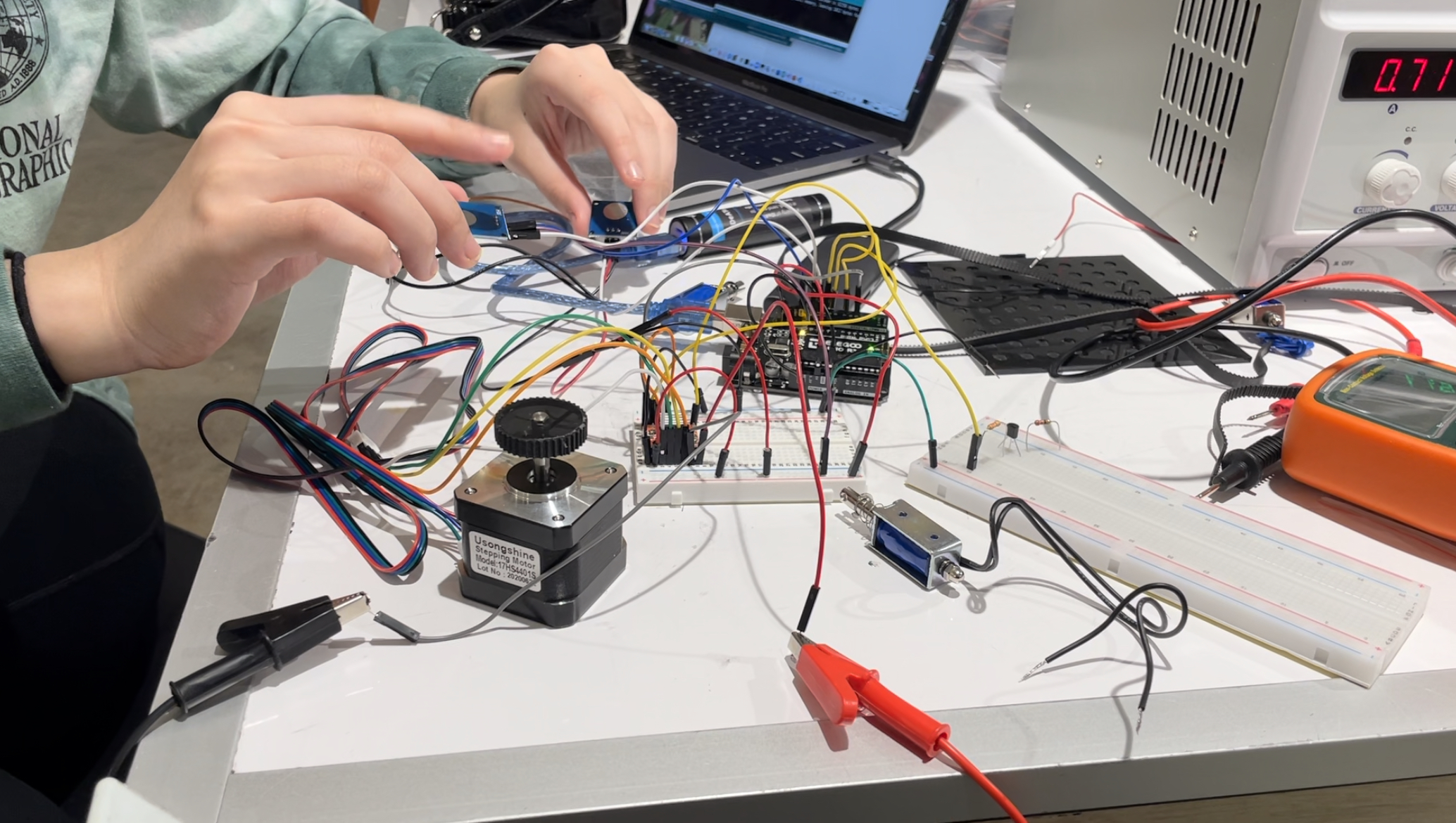
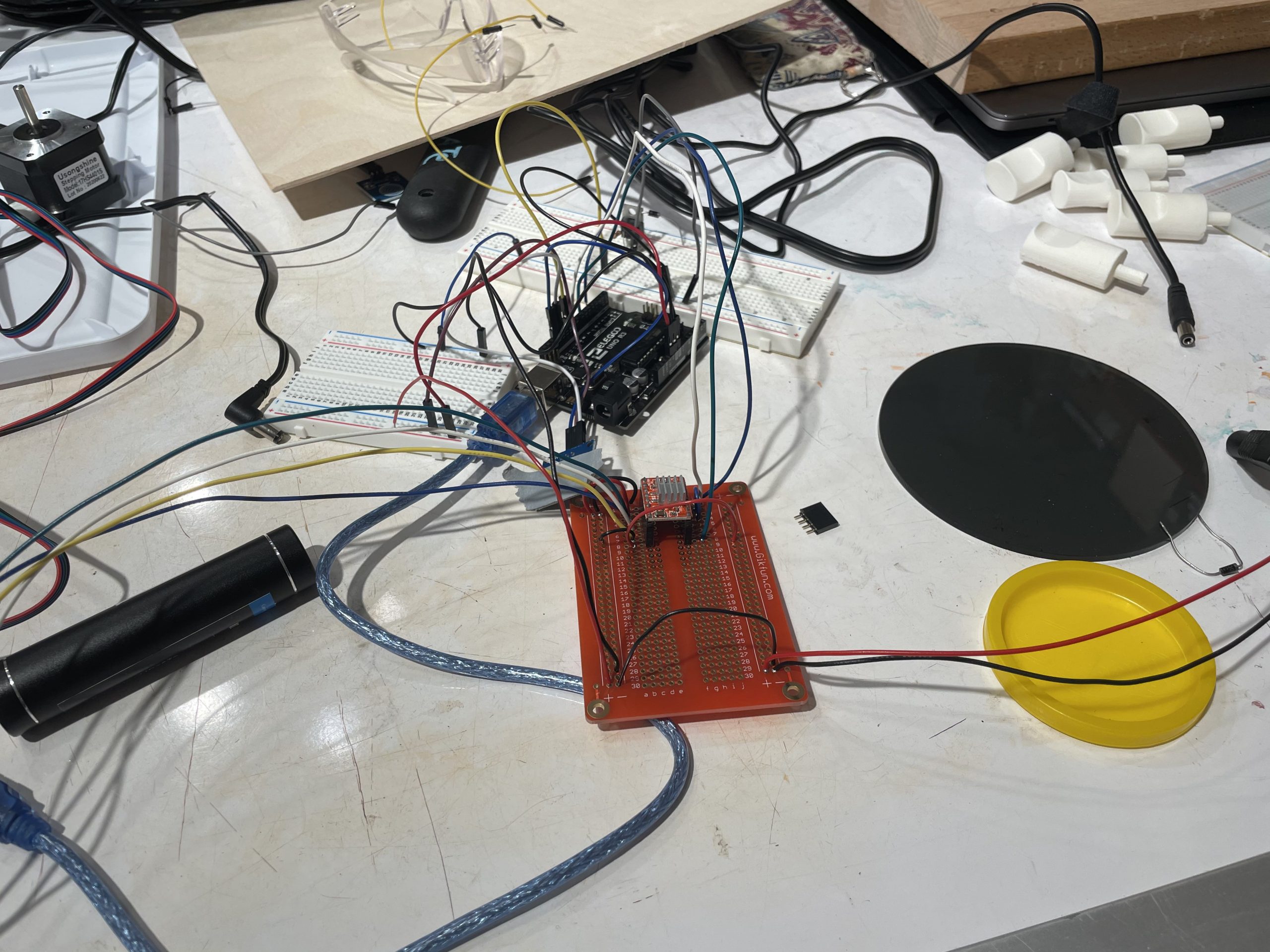
Using a larger solenoid for the larger device.
First version of solenoid wiring that worked. Later had to change the transistor.
Attempting to solder. Later not included because it mysteriously broke almost everything.
- 200 words addressing what you learned
- During the prototype process, the big questions were what did we want to use as a break for the device and how much torque would we need to rotate a lazy-susan and a cutting board. We decided to use a solenoid because the rod in it provides a concrete way of activating a break and releasing a break. We also knew we wanted a stepper motor to rotate the entire device. Since Jen can’t use her arms, we wanted to give her a convenient way to rotate the device, so the stepper motor and the solenoid in the prototype were controlled by a touch sensor. After critique, we knew we had to make everything bigger. We decided to go with a large solenoid which needs 12V to power it. We also went with a larger stepper motor because the original was far too small and couldn’t provide the torque we were looking for. The prototyping process was straightforward, but I had a lot of trouble wiring the larger solenoid. The 12V power supply fried multiple components and I had to research and retry different wiring combinations. It finally worked after we switched the type of transistor.
Process
The first time we brainstormed the pegboard idea
The making of the final wooden pegboard
Demonstration of technique used for gluing base so that the gears align with each other
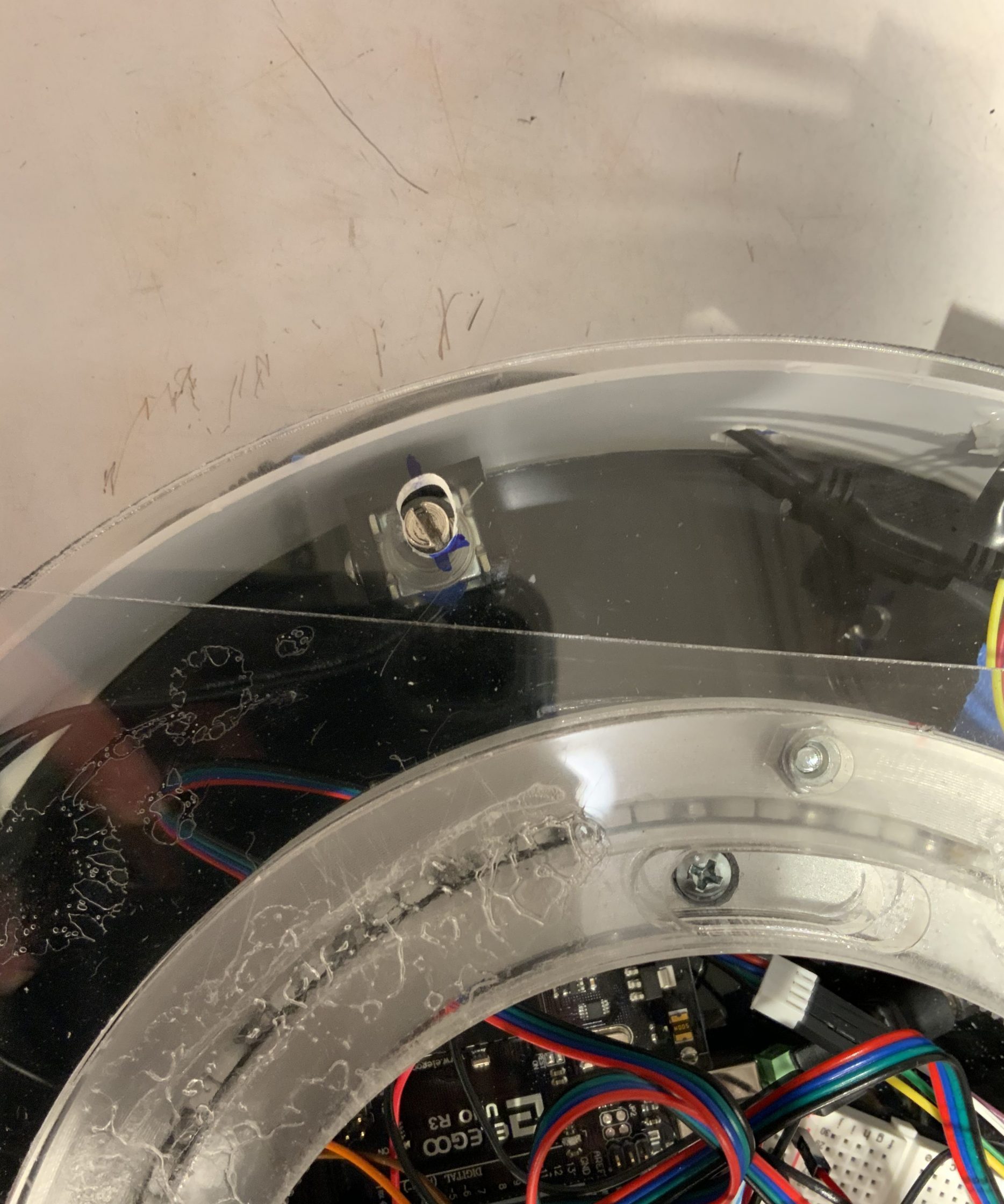
Close up of the solenoid braking mechanism used to lock the cutting board in place
Combining the electronics with the rotating device.
Putting the electronics, rotation device, and cutting board together.
The discovery made along the way came in determining the drive we would use to rotate the cutting board. Despite confidence in friction being enough to overcome the weight of the cutting board and the internal friction in the bearing, we found that it was extremely difficult to produce enough friction between the bearing and the motor in order to rotate the cutting board without slipping.
We also discovered that tolerances are everything when designing a braking mechanism. For our design, we initially thought that small holes fitting the diameter of the solenoid exactly would be more than enough to stop the rotation reliably, not taking into account the accuracy of the rotation drive itself. Instead, we found that it was extremely difficult to align the holes properly and thus ended up increasing the size of the holes to allow the solenoid to stop the cutting board more reliably.
Speaking to the process of building itself, we fell a little behind schedule because our expectations of build time were too optimistic. We initially planned to have everything done by the weekend before the project was due, but limitations in availability and materials meant that we had to spend a couple extra days finishing up the final product. We were, however, able to integrate everything on time as we had planned to finish the project 2 days early in order to account for hick ups along the way.
Conclusions and Lessons Learned
Working remotely on this project was the most challenging part because of the limited manufacturing and client interaction opportunities. In terms of manufacturing, COVID-19 restrictions on building open times and capacity made it difficult to schedule meetings to build and debug the project together. It forced us to be a lot smarter with our time, designing and debugging as best we could outside of the lab open hours in order to make the most efficient use of time and materials in the lab. In addition to limitations on work schedule, inability to meet Jen in person made it much more difficult to assess the extent of her capabilities and design specifically to her needs. While we were able to get video demonstrations of her capabilities, those were not nearly as clear as being able to view her actions first hand and understand from a first person point of view. Looking back, I think that more communication between us and Jen in the form of meetings, demonstrations, and emails would have given us more insight into things like movement limitations and space limitations so that we could design a gadget that better fit her workflow and space constraints.
The experience of designing for someone with a disability forced us to think more critically about the use of the product. The initial problem definition part in particular was a huge moment of learning as it forced us to think outside of our own experiences. Despite the challenges of doing this type of ideation remotely, we were surprised by the amount of personalization we could incorporate into the functionality of the device. After demonstrating our initial prototype to Jen, she was surprised at our solution as we had identified a problem that she hadn’t even thought about in having a cutting board that rotates. Being able to identify problems that weren’t on the radar of the client was a nice surprise.
Overall, we are extremely proud of the functionality of our end product. The stopping and turning mechanisms worked wonderfully and the peg board held vegetables much better than anticipated. Despite this success, future iterations on this design would include food safe and water safe components to increase longevity of the product. Cosmetic changes to the outside would also help improve the overall appeal of the device and would be something to consider more in the future.
Technical Details
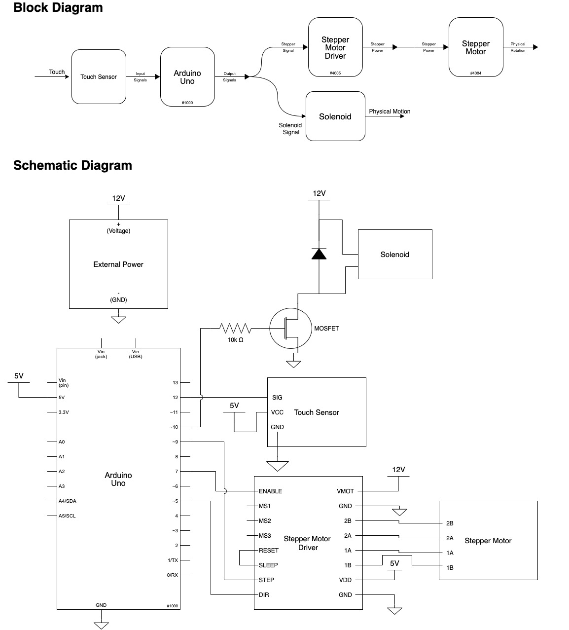
Schematic and Block Diagram
Code
/*
   60-223, Jen's Cutting Board
   Nicole Yu, James Kyle, Shuyu Zhang

   Description:
   This code encodes for a touch sensor (input), a stepper motor (output), and a
   solenoid (output). When the touch sensor is HIGH, the stepper motor rotates a
   number of steps and the solenoid activates to HIGH. The solenoid deactivates
   to LOW right before the stepper motor finishes a set amount of steps. There's
   a delay right after the motor finishes rotating so the touch sensor can't be
   continuously activated.

   Pin mapping:

   Arduino pin | type   | description
   ------------|--------|-------------
  12             input   Touch sensor signal
  7              output  Stepper motor enable pin
  9              output  Stepper motor step pin
  5              output  Stepper motor dir pin
  10             output  Solenoid pin

   Sources:
   1) Borrowed heavily from this Stepper motor library
   and code: https://www.arduino.cc/en/Tutorial/LibraryExamples/StepperSpeedControl
   2) Heavily reference this site to write the Solenoid:
   https://circuitdigest.com/electronic-circuits/solenoid-driver-circuit-diagram
*/

const int TOUCH = 12;
const int ENABLE = 7;
const int XSTEP = 9;
const int XDIR = 5;
const int BREAK = 10;

int rev = 145; //Number of steps stepper motor takes

void stepperFWD() {
  digitalWrite(XDIR, HIGH);
}

void setup() {
  pinMode(TOUCH, INPUT);
  pinMode(XDIR, OUTPUT);
  pinMode(XSTEP, OUTPUT);
  pinMode(ENABLE, OUTPUT);
  pinMode(BREAK, OUTPUT);
  digitalWrite(ENABLE, HIGH);
}


void loop() {


  if (digitalRead(TOUCH) == HIGH){
    digitalWrite(ENABLE, LOW);
    digitalWrite(BREAK, HIGH);
    delay(100);
    stepperFWD(); //Set direction of motor
    for(int i = 0; i < rev; i++){

      if(i > 100){
        digitalWrite(BREAK, LOW); //After 100 steps, release solenoid
      }
      motorStep();
      delay(10);
    }
    digitalWrite(ENABLE, HIGH);
    delay(2000); //After finishing steps, delay everything 2 seconds

   }else{
    digitalWrite(ENABLE, HIGH);
    digitalWrite(BREAK, LOW);
   }

}

void motorStep(){
  digitalWrite(XSTEP, HIGH);
  delay(5);
  digitalWrite(XSTEP, LOW);
}