Tinkercad Video
The potentiometer in this video is representative of our joystick middle step.
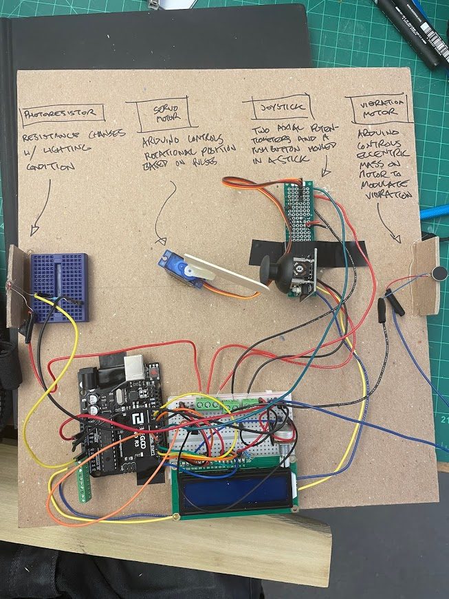
Overall photos for proportion and scale
Tate
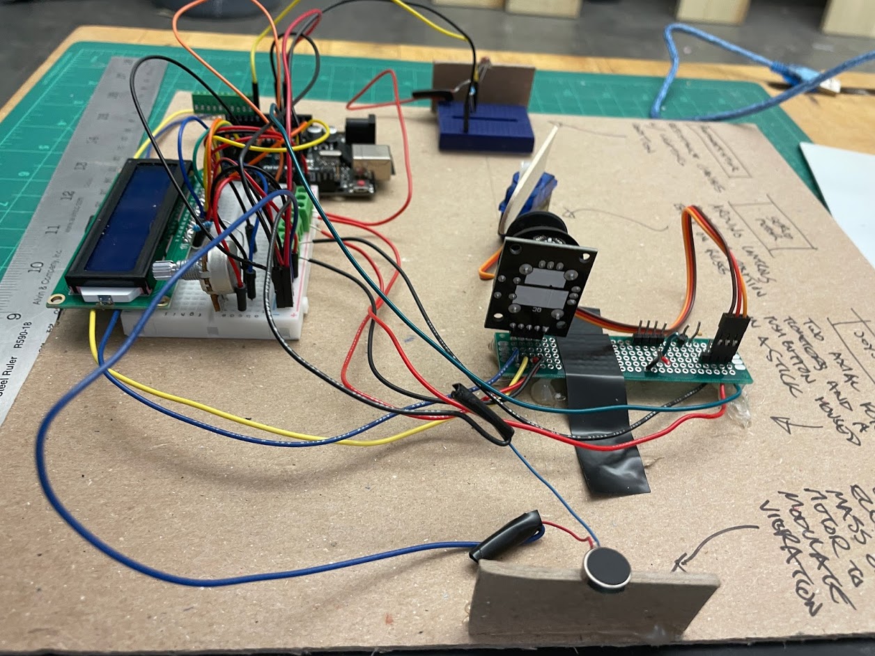
Tate’s final board
My final version had correct transduction and displayed values at good fidelity, but even with an added transistor to the vibration motor it drew so much current that it would dim the LCD screen, but otherwise, this version had a functioning double transduction.
Dominique
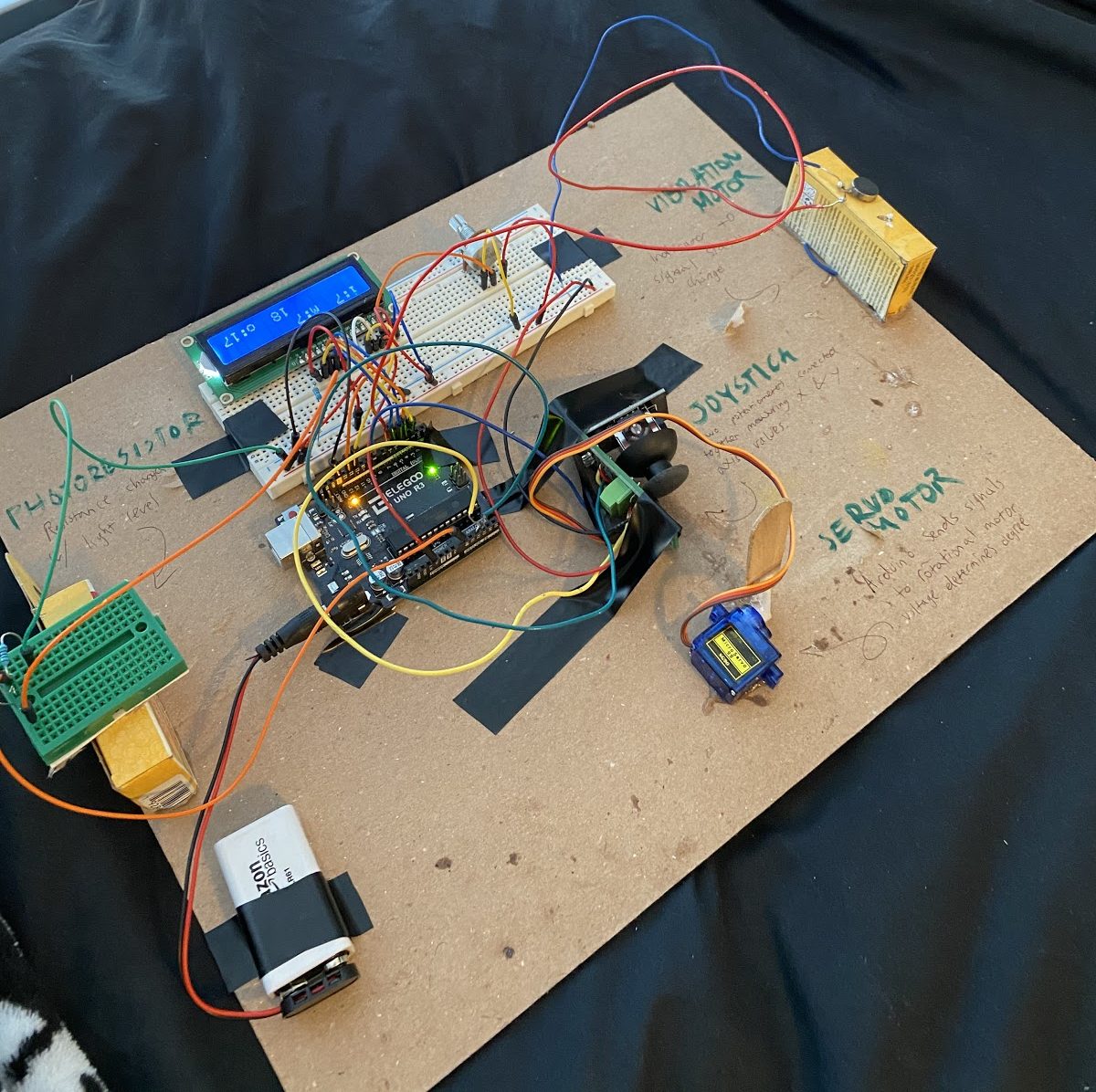
Dominique’s final board
At first I thought my final version had some wiring issues surrounding the vibration motor, but upon closer inspection, and the addition of a replacement vibration motor, my double transducer actually worked fine. The LCD sensor and actuator values were being displayed properly, and luckily, it did not dim when the vibration motor was triggered, and I did not use a transistor, so this was a peculiar but happy outcome.
Final Working Version in Chain
Prototype Details
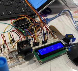
At first our LCD had many display issues. First the backlight would not turn on, then the values flashed too fast, and so forth. After implementing a special delay in void loop and switching libraries, we were able to fix the problems, at least on one of our prototypes.
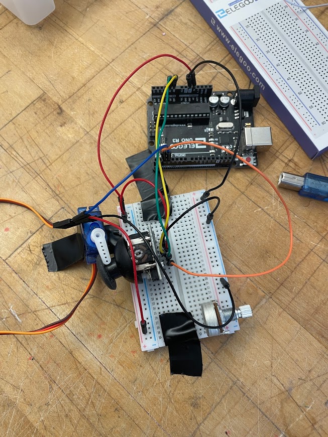
Servo-joystick prototyping
We used our two prototypes to test different things, Dominique’s explored the LCD more and mine focused on the mechanical interface from servo to the joystick.
Prototype video
Hopefully, you can hear the vibration motor buzzing in this video as I move the flashlight closer to the photoresistor on the other end of the board. And you can see the middle step (servo moving a joystick) as well. I had to cover the photoresistor with my hand in order to block out ambient light (that was really messing with the sensory data because it was a very bright room and my flashlight was dying), so you can’t quite see the flashlight action, but it’s happening, please trust me.
Simple narrative description
Our double transducer first takes in light in a room and records the brightness through the Arduino. That value is then used to determine the rotation degree of a servo motor; more light equals a higher degree up within a specified range. The servo pushes on a joystick, from which a y-Axis position is read and stored in Arduino. Finally, a vibration motor receives that output and vibrates more as the y-axis position increases.
Progress images
Tate
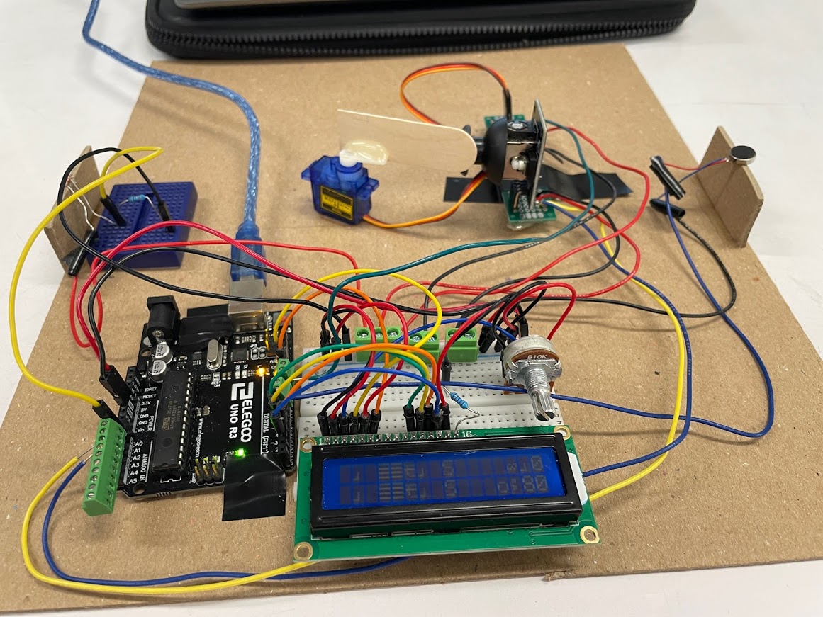
LCD hieroglyph issues
I struggled a lot with my LCD displaying odd values because of the vibration motor current draw creating noise in the circuit.
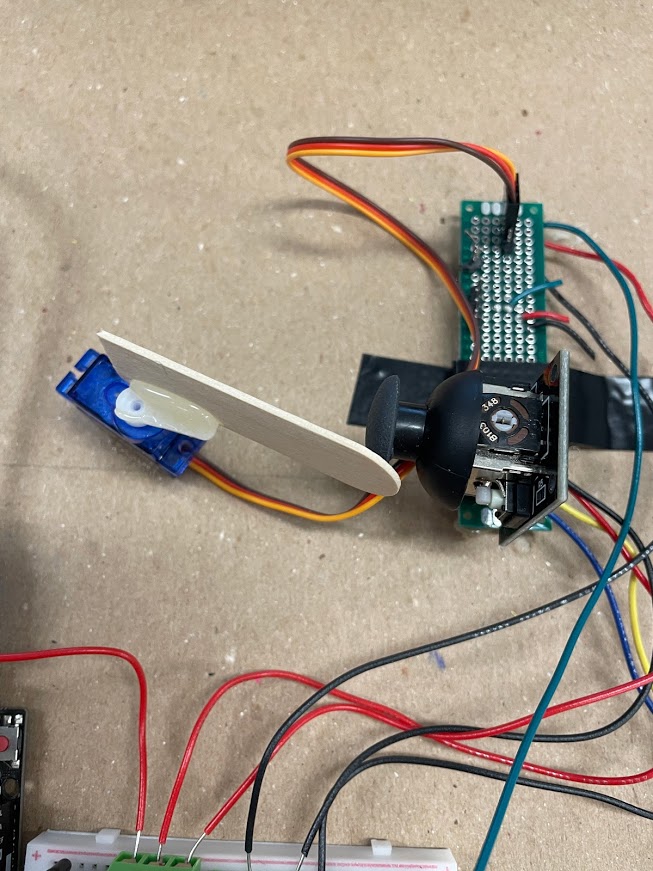
Servo-Joystick interface and soldering to protoboard
I also struggled a lot with soldering, as I accidentally grabbed a non-powered protoboard so after soldering my adapters for the servo and joystick I had a long period of debugging to find the cause of that. It was good soldering practice because I had to bridge connections with quarter-inch lengths of wire.
Dominique
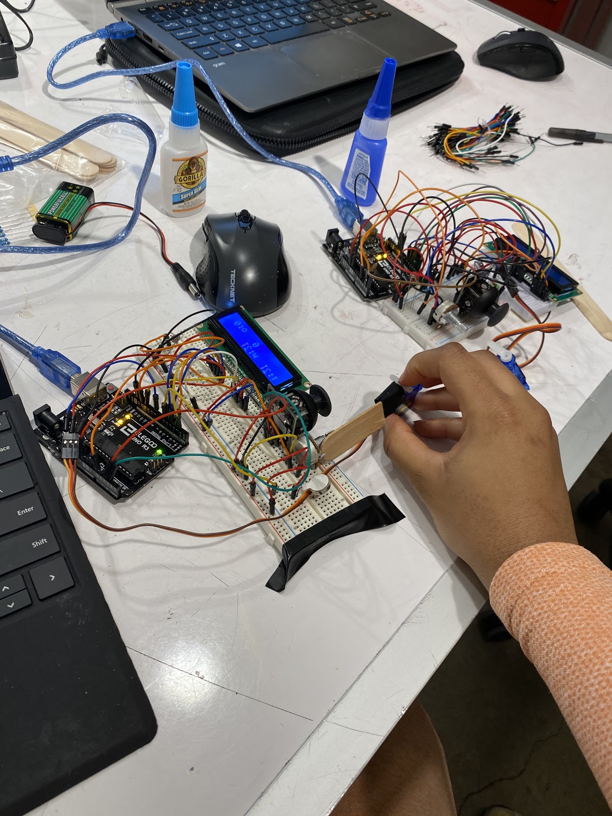
Prototyping popsicle stick connection
The hardware for this circuit was actually relatively simple to build, at least on the breadboard. The hard part was configuring the delicate servo to properly trigger the joystick. So as you can see here, that problem has not been solved yet.
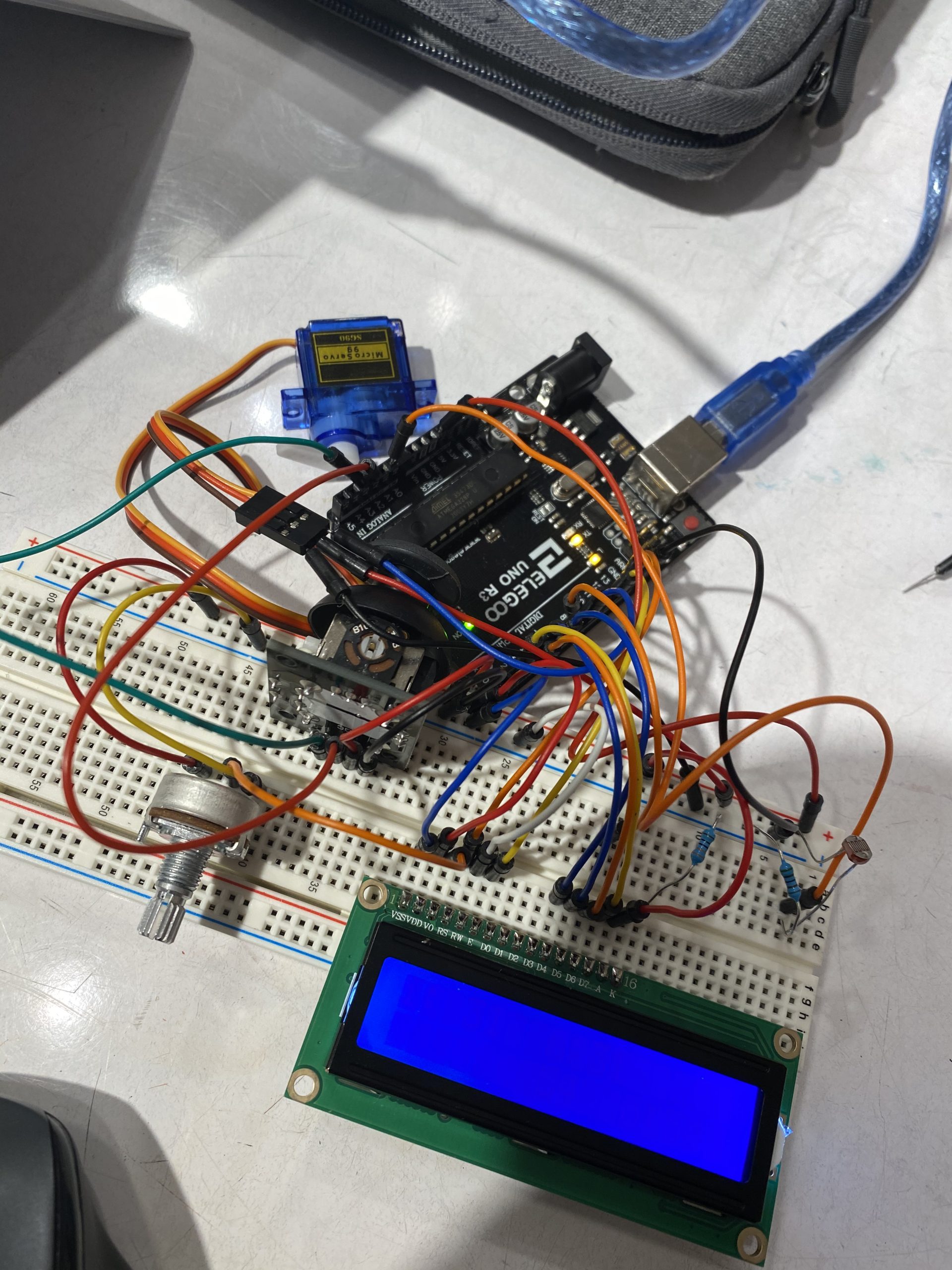
LCD prototyping
This was when the LCD still was not working properly. As you can see, it is not displaying anything, and that’s due to a number of reasons which are explained in detail in the Discussion section. The biggest problem here was that the LCD was wired incorrectly.
Discussion
Even though we went into the project anticipating the hardware components for wiring a transducer that involved a joystick would be complex, that part ended up not being that difficult and only took a short amount of time to configure.
As far as the difficult aspects of the project, we ran into a lot of hiccups with writing to the LCD. One of the issues was especially mundane and we did not realize it; for the longest time, the LCD would not display any coherent information, despite the code looking to be fine. After consulting with Zach, we discovered that we were not using the right library the whole time. We were using commands from LiquidCrystal_I2C and but the LCD we have does not have the I2C backpack. So not only did we not realize we had a different LCD than the tutorials, we were wiring it wrong. Anyway, we sorted this, fortunately, but the LCD on one of the two double transducers we built still had issues we could not troubleshoot.
We also had a strange issue where as our joystick value went up, the vibration intensity went down. We wanted both to increase in direct proportion. Turns out there was a typo for one of our map() functions where the value was reversed. Also we ended up writing a bit of extra code that constrained the max value of joystickVal which helped to keep our values in line.
Tinkercad also had its own set of issues. because some inputs could not be sensed by Tinkercad, we had to “fake it.” It was interesting figuring out how to do this, but ultimately not too challenging. Since the first input is light, we could simply make that value increase and decrease automatically and the rest of the sensors and actuators respond accordingly. Because there’s no joystick in Tinkercad, we replaced it with a potentiometer, just to clarify.
There’s also the issue of figuring out how to get the tiny servo arm to push the joystick, which does not budge very easily. We used superglue to glue half a popsicle stick to the arm, as you can see in the photos, and we taped down the motor, which did help. The motor on one transducer pushed sideways on the joystick, and the motor on the other was configured to push downward, and both seemed to work fine.
Finally, for one of the two double transducers we built, it unfortunately broke after working properly a few times. The cause of the break is still kind of unknown even after checking the serial monitor and wiring. Because it was only the vibration motor that stopped responding even though the vibration value was displaying appropriately, we figured it was a wiring issue, one of the complications from a less-than-stellar soldering technique. It did look like the vibration wires were burned and not very attached, but after replacing the vibration motor and still finding issues, we figured the problem was deeper in the hardware. That was until I switched power sources and everything was completely fine. I agonized for hours over this very simple issue (Dominique).
For future projects it certainly would be useful to get a better grasp on soldering with a steady hand. That did not seem to be my strong suit, and I’m sure it will be a useful skill for the future (Dominique).
Functional block diagram and schematic
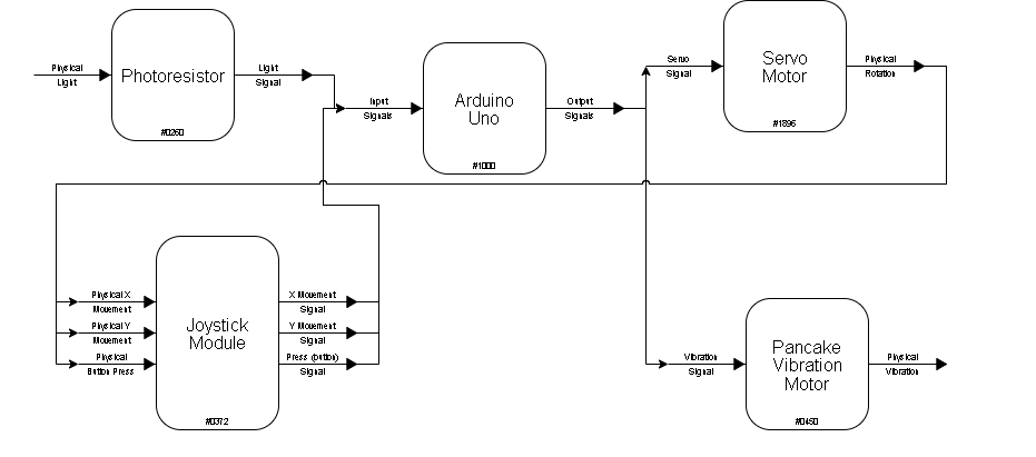
Block diagram
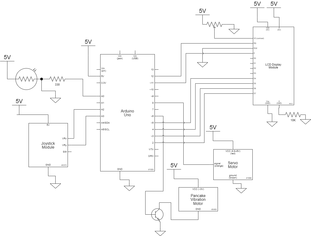
Schematic drawing
Here is the code
/*
  Double Transducer: Light to Position to Movement
  Dominique Aruede and Tate Johnson

  Description:
  Takes in a light value which informs the degree rotation
  of a servo arm which pushes a joystick which informs the
  vibration intensity of a vibration motor.

  Pin mapping:
  Arduino pin | type   | description
  ------------|--------|-------------
  A0            input     photoresistor for initial input
  A2            input     reads joystick x axis (only needed in this sketch to keep the y axis stable)
  A3            input     reads joystick y axis
  A4            input     reads vibration motor output
  2             output    writes to pin D7 on LCD
  3             output    writes to pin D6 on LCD
  4             output    writes to pin D5 on LCD
  5             output    writes to pin D4 on LCD
  6             output    writes to vibration motor
  8             output    writes to servo motor
  11            output    writes to enable pin on LCD
  12            output    writes to RS pin on LCD

  Collaboration and sources:
  - https://www.arduino.cc/en/Tutorial/LibraryExamples/HelloWorld
  - https://canvas.cmu.edu/courses/22031/modules (photoresistor asynchronous lecture)
*/

#include <Wire.h>
#include <LiquidCrystal.h>
#include <Servo.h>

//pin constants
const int PHOTORESPIN = A0;
const int SERVOARMPIN = 8;
const int JOYSTICKPINx = A2;
const int JOYSTICKPINy = A3;
const int VIBRATIONPIN = 6;
const int rs = 12, en = 11, d4 = 5, d5 = 4, d6 = 3, d7 = 2;
const int WAIT = 300;
unsigned long timerVariable = 0;


int lightVal = 0;
int armVal = 0;
int joystickVal = 0;
int vibVal = 0;

/* Create an LCD display object called "screen" with I2C address 0x27
    which is 16 columns wide and 2 rows tall.*/

LiquidCrystal lcd(rs, en, d4, d5, d6, d7);
Servo arm; // make a servo object

void setup()
{
  // initiate pins
  pinMode(PHOTORESPIN, INPUT);
  pinMode(JOYSTICKPINy, INPUT);
  pinMode(VIBRATIONPIN, OUTPUT);


  // servo is plugged into the assigned pin on Arduino
  arm.attach(SERVOARMPIN);

  //LCD setup
  lcd.begin(16, 2);

}

void loop()
{

  //digitalWrite(VIBRATIONPIN, HIGH);
  //convert light sensing to right range
  lightVal = analogRead(PHOTORESPIN);
  int LCDlightVal = 0;
  LCDlightVal = map(lightVal, 0, 1023, 0, 99);

  //write to the transducer first part
  armVal = map(lightVal, 0, 1023, 0, 170);
  int LCDarmVal = 0;
  LCDarmVal = map(lightVal, 0, 1023, 0, 99);
  arm.write(armVal);

  //read the second transducer part
  joystickVal = analogRead(JOYSTICKPINy);
  if (joystickVal >= 512) {
    joystickVal = joystickVal - 512;
  }
  else {
    joystickVal = 0;
  }
  int LCDjoystickVal = 0;
  LCDjoystickVal = map(joystickVal, 0, 512, 0, 99);

  // write to output
  vibVal = map(joystickVal, 0, 512, 0, 255);
  analogWrite(VIBRATIONPIN, vibVal);
  int LCDvibVal = 0;
  LCDvibVal = map(vibVal, 0, 255, 0, 99);


  if (millis() - timerVariable > WAIT) {
    lcd.clear();
    lcd.home();
    lcd.print("i:");
    lcd.print(LCDlightVal);
    lcd.print("  m:");
    lcd.print(LCDarmVal);
    lcd.setCursor(8, 1);
    lcd.print(LCDjoystickVal);
    lcd.setCursor(12, 1);
    lcd.print("o:");
    lcd.print(LCDvibVal);
    timerVariable = millis();
  }
}
