Stepper motors
Intro
A stepper motor combines some aspects of a regular vanilla DC motor with some aspects of a hobby servomotor.
Like a DC motor, it can turn continuously (though it can’t go as fast as a DC motor). Like a hobby servomotor, you can tell it precisely what position to go to. Here’s a summary table:
| motor type | spins continuously | position-controllable | speed controllable | holds its position when stationary | requires driver circuitry |
| DC motor | yes | no | yes (just vary the voltage) | no | yes (to provide enough current) |
| hobby servomotor¹ | no | yes | no | yes | no (the device contains its own driver circuit) |
| stepper motor | yes | yes | yes | yes² | yes (to provide enough current and to control its movement) |
¹ This table is referring to the type of servomotor that’s included in the course kit. However, there are also “continuous rotation” hobby servomotors, where changing the value of
servo.write()will change their speed and direction, rather than position.
² A stationary stepper, when powered, holds its position. When it’s not powered, it will be free to rotate.
How it works
A DC motor contains a copper coil as well as some permanent magnets. When an electrical current runs through the copper coil, it becomes an “electromagnet” and produces a magnetic field. The physical arrangement of the inside of a DC motor means that the “push” of the opposing or “pull” of the attracting fields will make the motor’s shaft spin. We will take advantage of this effect to make a different type of motor: a stepper motor.
Full steps
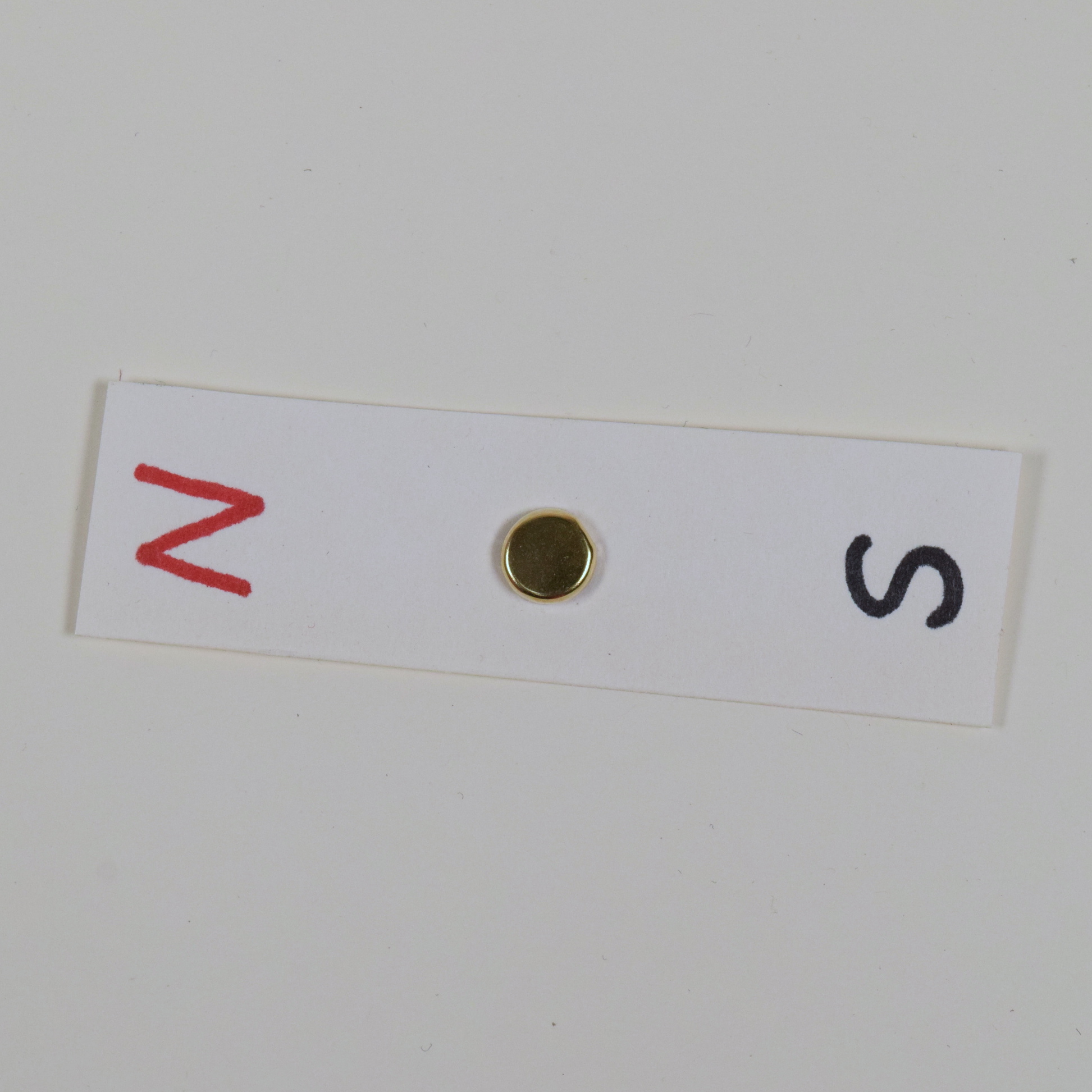
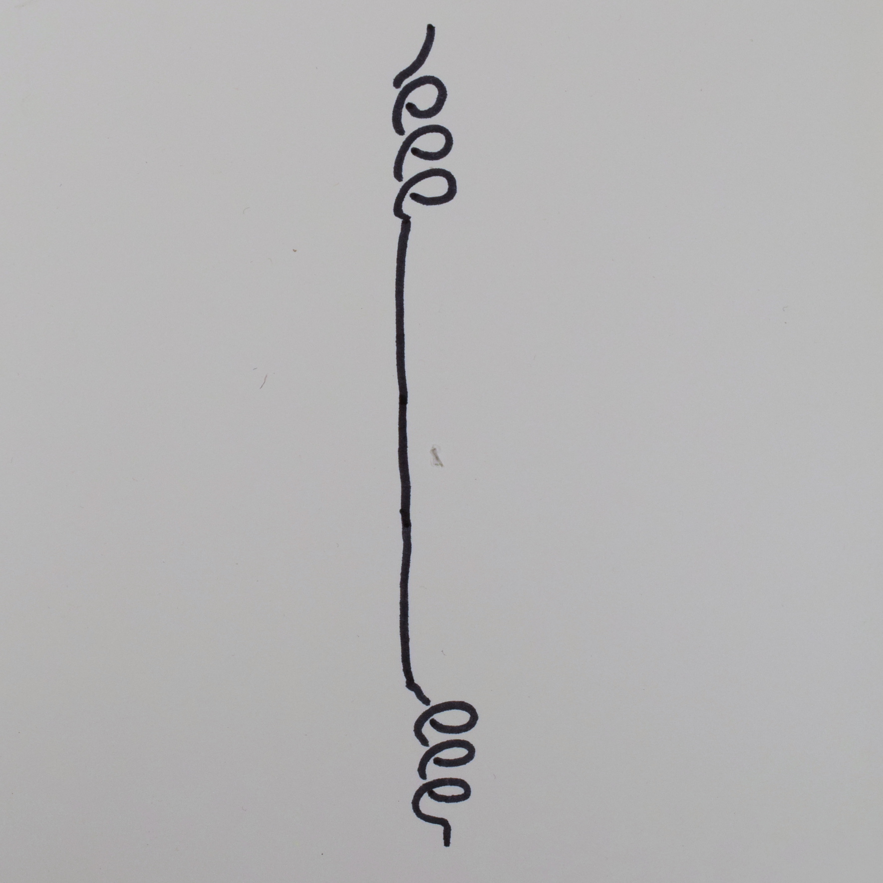
A DC motor shows us that it’s possible to make a spinning thing driven by a magnetic field. Now, let’s build a stepper motor from scratch to understand how it works. We start with a permanent magnet on a pivot; this represents the motor shaft. Now we’ll add something to make it turn. To do this, we’ll take a copper wire coil and separate it into two halves. We arrange one of these halves at 12 o’clock and the other at 6 o’clock:
If we pass an electric current through the coil, then it will become a magnet. Let’s pass the power through from bottom to top; that will make the coil a magnet like so:
To build the motor, we’ll arrange the coil so it’s around the bar magnet:
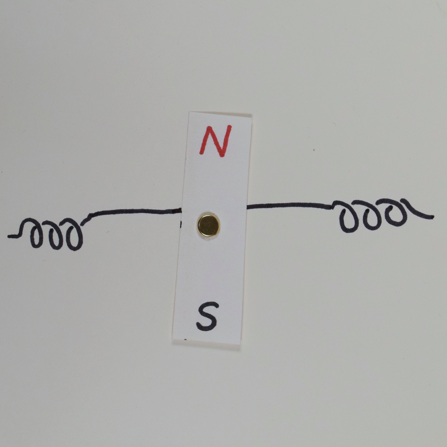
When there’s no electricity flowing, the magnet is free to spin around and is totally unemcumbered by the coil. But what about when the coil is energized? Then the magnet rotates to align with the magnetic field it’s encountering, like so:
This is a “motor” that only goes to one position. How can we move it? Let’s reverse the current flowing through the electromagnet—that will reverse the electromagnet’s field and now the magnet will spin 180º (we don’t know which way it will go) to align with the new field:
Aha! We now have a two-position stepper motor. It can turn its shaft to 12 o’clock or 6 o’clock, but nowhere in between. Adding another coil, this one oriented perpendicular to the first, will give us new possibilities:
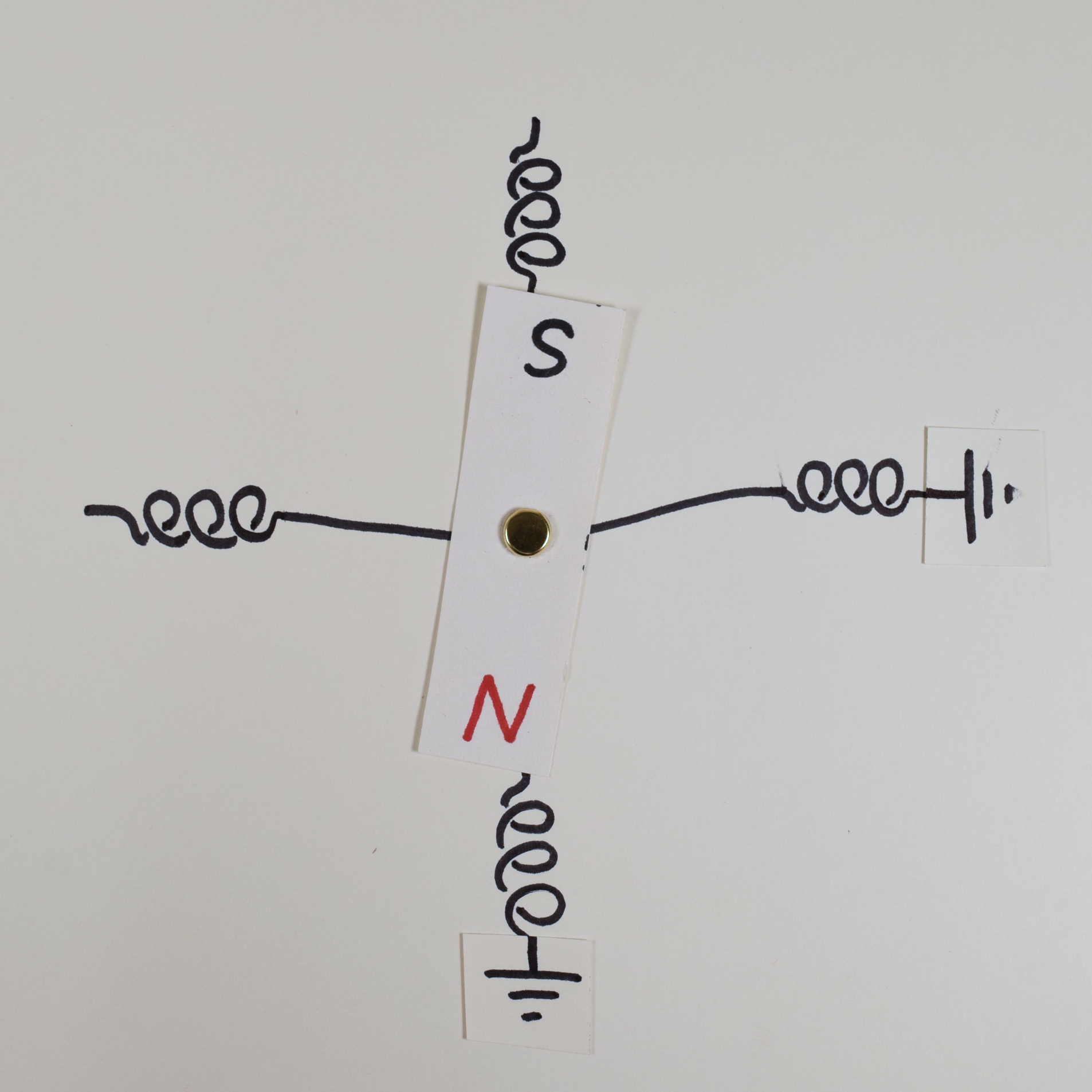
Now, we can also make the magnet’s north end point to 3 o’clock (by running power through the new coil left to right), or to 9 o’clock (by running power through the new coil right to left):
In each example above, we made the magnet point straight towards a coil. In stepper motor terminology, these are called “full steps.” Any stepper motor has the same number of full steps available as the number of coil pairs running around its periphery. In other words, the number of full steps on any motor is a function of the mechanical design of its internals.
Half steps
Using a control circuit, we can now steer the shaft of our motor to one of four positions. But it turns out we’ve got many more options than that. What if we power both coils at once? For instance, powering the 12 o’clock/6 o’clock coil to pull the magnet’s north end to 12 o’clock, and powering the 3 o’clock/9 o’clock coil to pull the magnet’s north end to 9 o’clock? The north end will feel equal pull towards 12 o’clock and 9 o’clock…and it will land in the middle, like this:
Aha! Now we have not four, but eight possible places we can point the magnet, by manipulating the direction of the power flowing through both of our coils. When we power multiple coils like this, so that the magnet is pulled between neighboring coils, that’s called “half stepping.” Any stepper has twice as many half-step positions available as full-step positions.
In addition to “half steps,” there are also “quarter,” “sixteenth,” and even “thirty-second” steps, all of which are created by varying the strength of the magnetic field between two neighboring steps. Using smaller step sizes gives you more control over the motor’s movement at the expense of available torque and speed.
Real stepper motors
Real stepper motors don’t have just four full steps available. Instead, the most common value is 200 steps per revolution. How do they do that? By winding the coils in a more complicated way than the simple diagrammatic one shown above, and using cleverly designed mechanical teeth which steer the magnetic field precisely the way they want it to go. Here’s a gif showing one flavor of stepper motor, which has four coils, going through four very small steps as the coils fire in sequence:
 (Image from authors Wapcaplet and Teravolt via Wikimedia Commons)
Practical use
Driving the stepper motor with the A4988 chip
The easiest way to drive a stepper motor using an Arduino is to pair it with an A4988 chip (IDeATE part number 4988), which will interface with the motor and deliver the power it needs. Most steppers that IDeATe carries use an approximately 12V power supply.
The stepper motors that we have in stock in IDeATe have four wires coming out of them: two of them are ends of an internal coil, and the other two are the ends of another internal coil. These are called “bipolar stepper motors.” The schematic diagram of this type of motor is this:
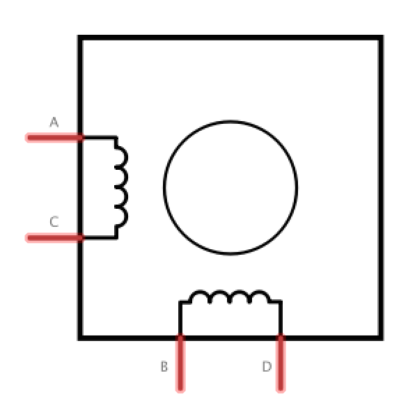
Determine the motor wiring
You’ve got four wires coming out of the motor, and as the schematic shows, there are two pairs among them. To wire the motor properly, you must figure out which are the pairs.
Use a multimeter in its resistance mode (i.e. as an ohmmeter) to determine the correct wire pairings. If you test resistance between one wire and another and see less than ~200Ω, then those two wires are opposite ends of the same coil. If you see a resistance that’s very high, such as 100kΩ, then those wires are part of different coils.
Once you’ve determined the proper coil pairs, mark the paired wires with tape, or write down the colors of the pairs. You’ll need to know the coil pairs to wire the motor properly.
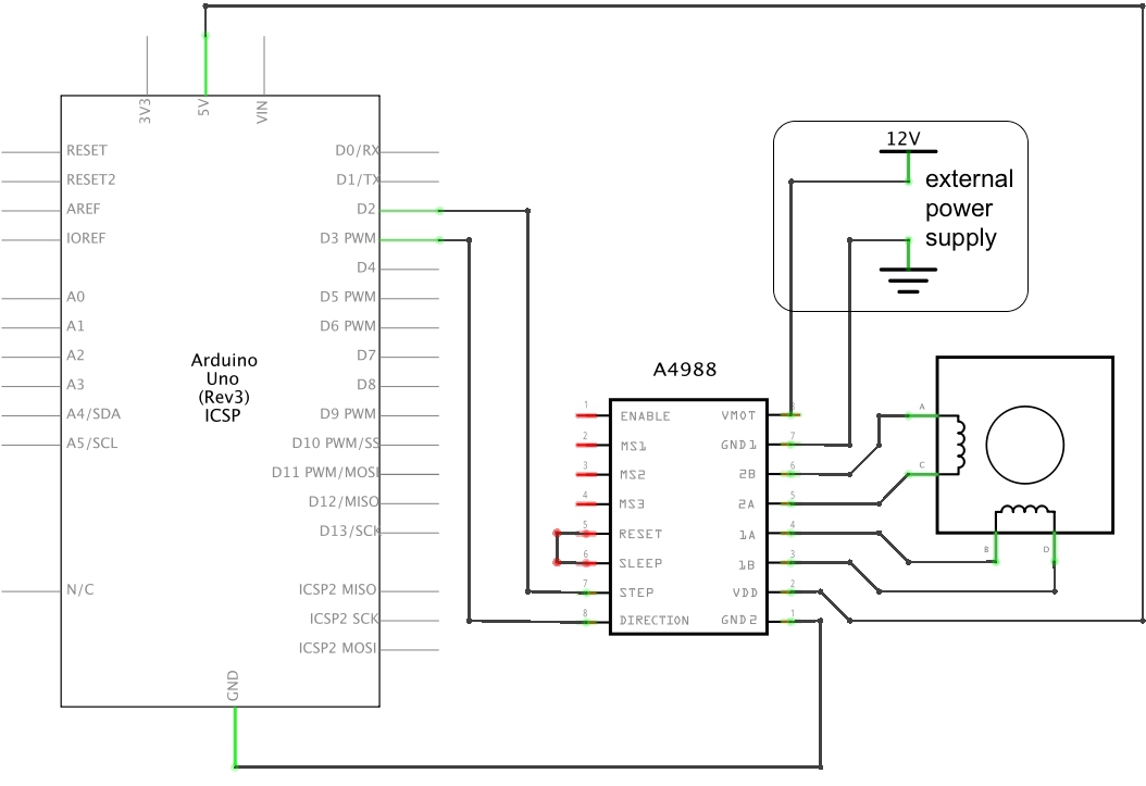
Build the circuit
The A4988 driver chip does a lot of work: it keeps track of which coils to run in which direction to make the motor take a step. The chip only has two data connections to the Arduino: one wire which tells the driver whether it should be stepping clockwise or counterclockwise (the “direction” pin, DIR in the schematic below), and the other wire that tells the A4988 that it should initiate a step (the “step” pin, STEP in the schematic below).
A few notes on wiring this part:
-
The A4988 has two different power supplies. Don’t mix them up!
- The
VDDsupply gives the A4988 the power it needs to run its own internal logic; it runs on 5V from the Arduino. - The
VMOTsupply is the one that will be providing the power to run the motor. Typically you should provide 12V into this port, from an external power supply.
- The
-
Note the little jumper wire from the
RESETpin to theSLEEPpin; if you omit this, the chip will probably do nothing because it will be in “sleep mode.” -
Any two digital I/O pins on the Arduino can be used for the
STEPandDIRconnections. This example will use pins2and3but these can be changed if you’d like.
If you want to “microstep” the motor—i.e. use anything other than full steps—simply add jumpers from pins MS1, MS2, and/or MS3 to 5V. If you jumper MS1 to 5V, it will half step; jumper MS2 to 5V and it will quarter step; jumper MS1 and MS2 to 5V and it will eighth step; jumper all three of them (MS1, MS2, and MS3) to 5V and it will sixteenth step. If you want to change microstepping as the motor is running, you can drive the microstep pins from Arduino digital logic ports (digitalWrite(HIGH) any pin to turn its microstepping switch on, and digitalWrite(LOW) to it to turn it off).
Running the software
There are a variety of libraries for driving stepper motors. The AccelStepper library, written by Mike McCauley, is excellent and very full-featured. The example below uses that library.
#include <AccelStepper.h>

const int STEP_PIN = 2; // A4988 "STEP" pin wired to Arduino pin 2 (you can change this)
const int DIR_PIN = 3; // A4988 "DIRECTION" pin wired to Arduino pin 3 (you can change this)

// make an AccelStepper motor object. "myMotor" can be any name you'd like.
AccelStepper myMotor(1, STEP_PIN, DIR_PIN);

int pos = 800; // variable to store motor position instruction

void setup(){
  Serial.begin(9600); // begin Serial communication

  // you can change the below values as you'd like
  myMotor.setMaxSpeed(1000); // measured in steps per second
  myMotor.setAcceleration(500); // measured in steps per second squared

  /*
      The following line will send an instruction to move the motor to position 10000,
      which would mean 50 full rotations if the motor has 200 steps/revolution
  */
  myMotor.moveTo(10000);

  /*
     To make the motor actually move, you must call the function myMotor.run()
     as often as possible. Here, I keep calling it over and over using a while()
     loop until the motor arrives at its destination
  */
  while (myMotor.distanceToGo() != 0) { // while there is still a distance to go,
    myMotor.run(); // make the motor run
  }
  // as soon as this while() loop exits, the setup() will be done and the loop() below will begin
}

void loop(){

  if (myMotor.distanceToGo() == 0) { // if the motor arrived
    pos = -pos; // then change its destination
    myMotor.moveTo(pos); // and tell the motor to go there

    // You can use Serial feedback to see what the motor is up to
    Serial.print("current position: ");
    Serial.println(myMotor.currentPosition());
  }

  myMotor.run(); // remember, you must call this function as often as possible

}
