The goal of the project was to design an assistive device for someone else. We were to get to know our client and understand where in their life…
1. Introduction The topic of our final project is to design and build a device for our client with physical difficulties. We get to understand our client’s needs…
This class teaches students how to design and fabricate mechanisms that utilize Arduino/small electrical components. This project was intended to allow students to interview a client with a…
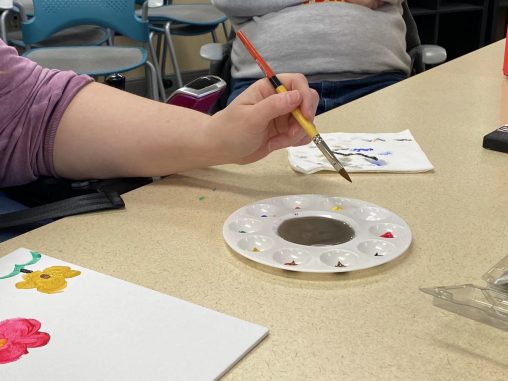
Inspiration Capture Device by Team Callisto: final documentation The Inspiration Capture Device (ICD) is the product of weeks of collaboration with our team’s client, Mary. After meeting with…
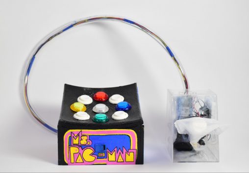
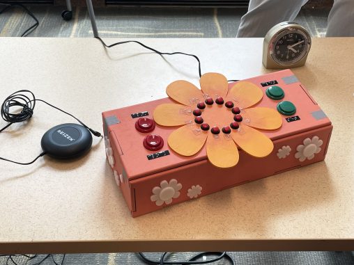
Gaming Keyboard and Mouse by Team Dione: Final Documentation The goal of this project was to create a specialized keyboard and mouse for our design client, Kim, to…
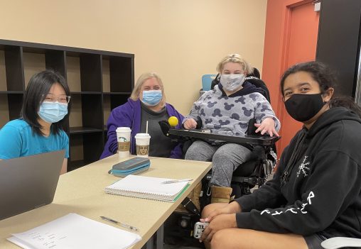
Introduction The project objective is to design an assistive device for our client with physical difficulties. On Mar. 21, 2022, we held a short interview with our client,…
Introduction This is the documentation for the two interviews our team, team Dione, conducted with our client Kim and her father Bob. The purpose of this interview was…
Introduction: Team Callisto had the opportunity to speak with Mary D’Ottavio to design an assistive device for Mary’s daily life. Through the Ideate: Physical Computing course at CMU…
Introduction Our goal with the project is to create a personally tailored device that makes one aspect of our client’s life better. To better meet this goal, we…
A Brief Introduction For the final project in Physical Computing, we have formed a team of three (Team I/O) in order to create an accessible device for someone…
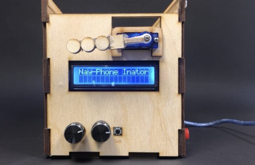
A device to help lock away your phone for a specified amount of time so you can focus on tasks at hand. Process Images and Review Discussion The…
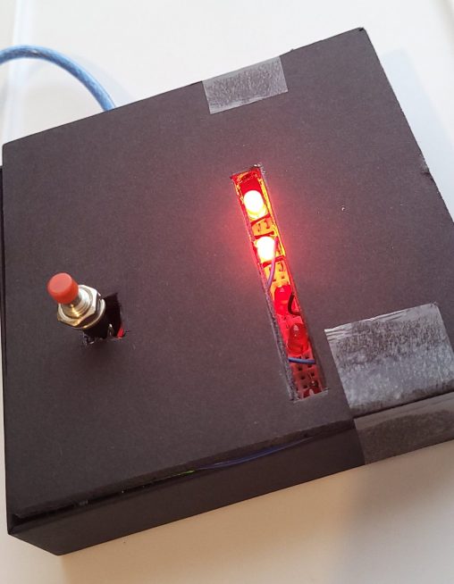
The Exercise Set Tracker (EST) helps me keep track of my 5×5 sets during workouts with just the push of a button. Process One decision point in my…
The SunLight Cassie Rausch The SunLight is an alarm clock that relies on a bright light to wake up the user rather than a loud noise. Process When…
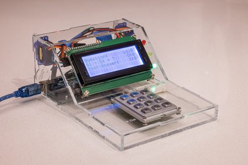
Overview Math Buddy is my new electronic friend who always wants to improve my math by asking me mathematical questions and expecting my responses. If I answer correctly,…
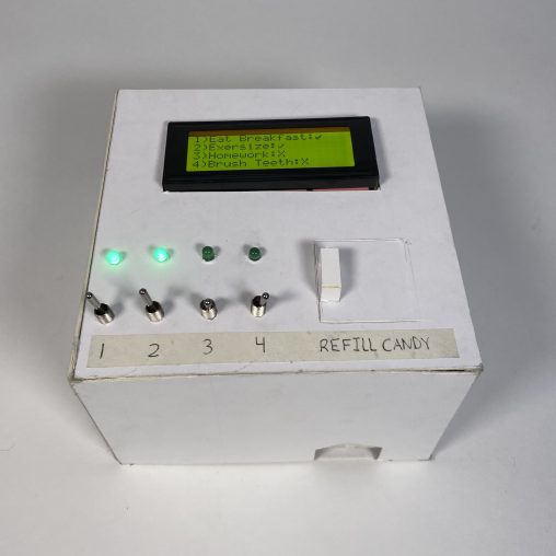
For Project 2, I created a checklist that rewards me for establishing good habits. Photos and Videos Process Images Above is my initial design idea of the Good…
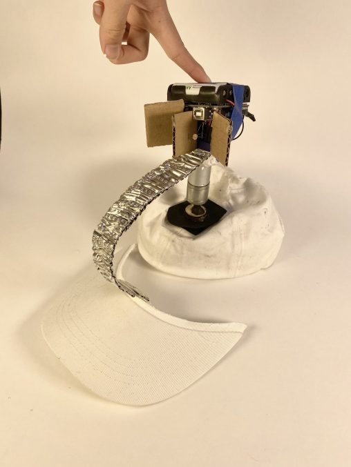
60223 Project 2 – David Wu Smart Hat with Rotatable Brim This smart hat can detect where the brightest light is (usually the sunlight), and rotate the brim…
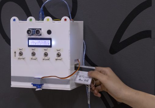
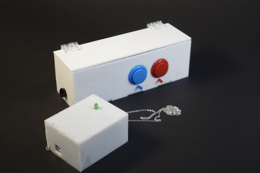
This device reminds me to bring my things with me in the morning. If I have everything listed with me, a latch opens and my ID falls out…
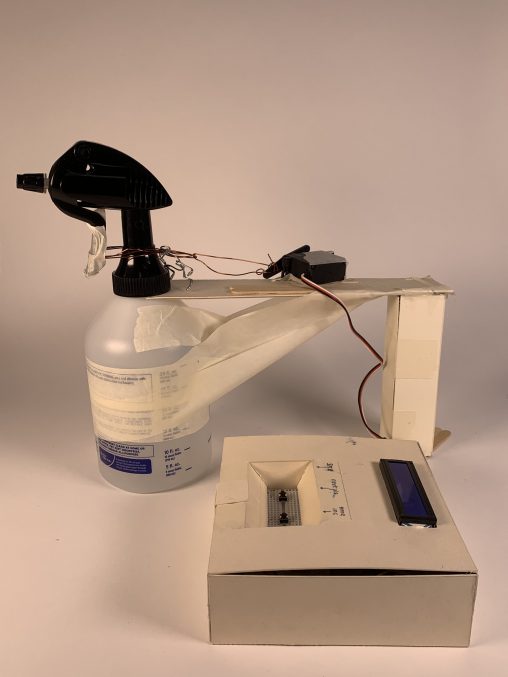
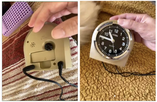
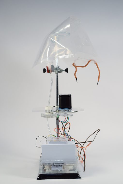
My project 2 was an alarm clock specifically meant for taking naps and incentivizing you to not hit the snooze button. Here is the machine in action, spraying…
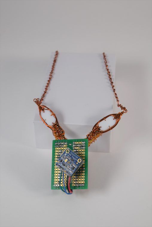
The chameleon necklace changes color to match its surroundings, allowing users to match their jewelry to their outfits. Detail Photos: Necklace in Use: Video: The necklace changes…
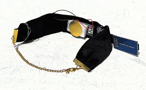
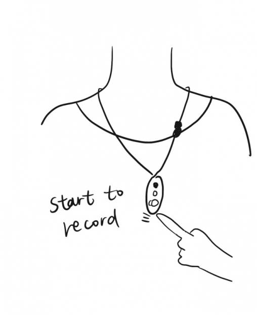
This is a choker that can start recording autonomously when it detects the user humming unconsciously in the bathroom. Process The first change I recorded is the choice…
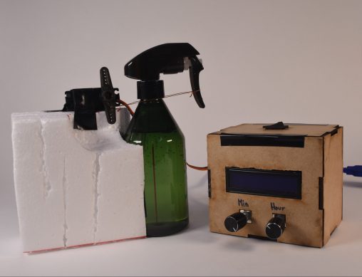
Water-spray Alarm Clock A servo-activated alarm clock that instantly wakes you up by spraying water. Images Short clip of alarm clock Decision…
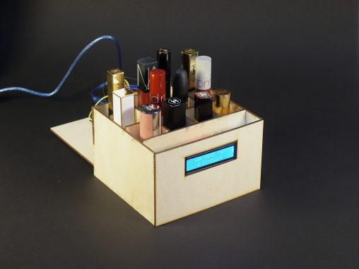
Do you have the trouble of having too many lipsticks and not knowing which one to use? Try this lipstick container! It can pick out your lucky color…
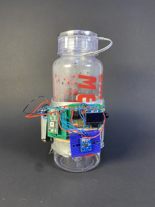
Hydro Task is a device that tracks how much water the user drinks throughout the day with the purpose of encouraging the user to meet their hydration goals. Overall…
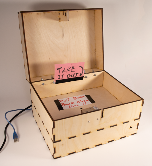
This box reminds the user to write something down at the end of every day to entice journaling habits! This video demonstrates how the box works. The box…
Design Concept This is a water hourglass that helps users to achieve daily water drinking goal, using water as a dripping timer and also the consuming product itself….
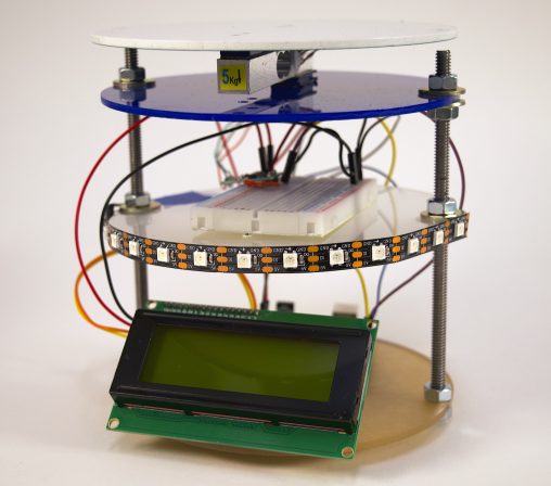
Device Function: The core of this device is a scale that weighs the amount of water in a bottle and updates how much of your goal you have…
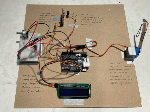
Narrative Description When the potentiometer is turned it tells the buzzer to make sound and then the noise sensor listens to this sound and tells the servo to…
Project I: Y-Axis Magnetic Field to Wheel of Color Images of Final Project Overall photo for proportion and scale 2. Details of part to highlight 3. Brief movie…
Photos that show scale: Jerry ‘s scale for a ruler Videos: Progress images: Wiring before the RGB sensor was put in Here is the soldered RGB sensor! This…
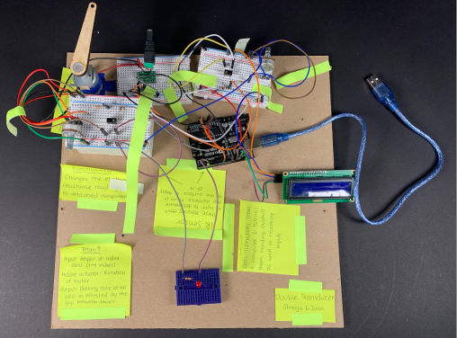
Close-ups Narrative description For our double transducer, we were tasked with converting the height of an index card, ranging from 1 to 4 inches,…
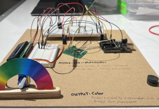
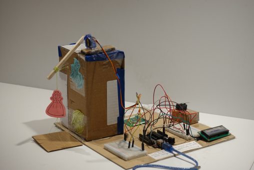
Images and Videos Description This Double Transducer takes in the brightness of light as an input and converts that into a rotational position and then finally converts that…
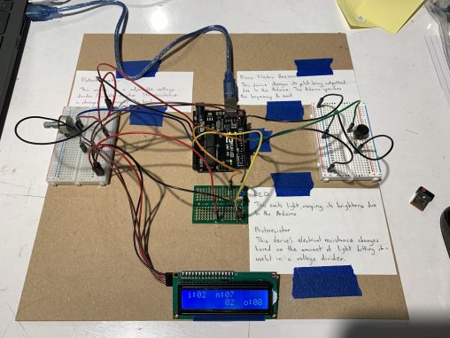
60223 Project 1 – David Wu and Jiaying (Vina) Wei Double Transducer: Flight of the Bumblebeep This double transducer takes in a rotational input of 10-80 degrees, and…
Detail Photos: Videos: Video demonstration of Lynn’s double transducer. Video demonstration of Yongwen’s double transducer. Narrative Description: Our double transducer takes…
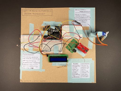
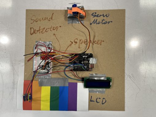
Gallery Description This device transfers light into sound, into movement. A small device measures light. An LED light will blink at different rates, and depending…

Narrative Description The double transducer receives input in the form of rotational speed and the final output is magnetic field strength. The intermediate output is an angular…