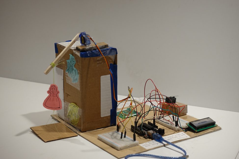
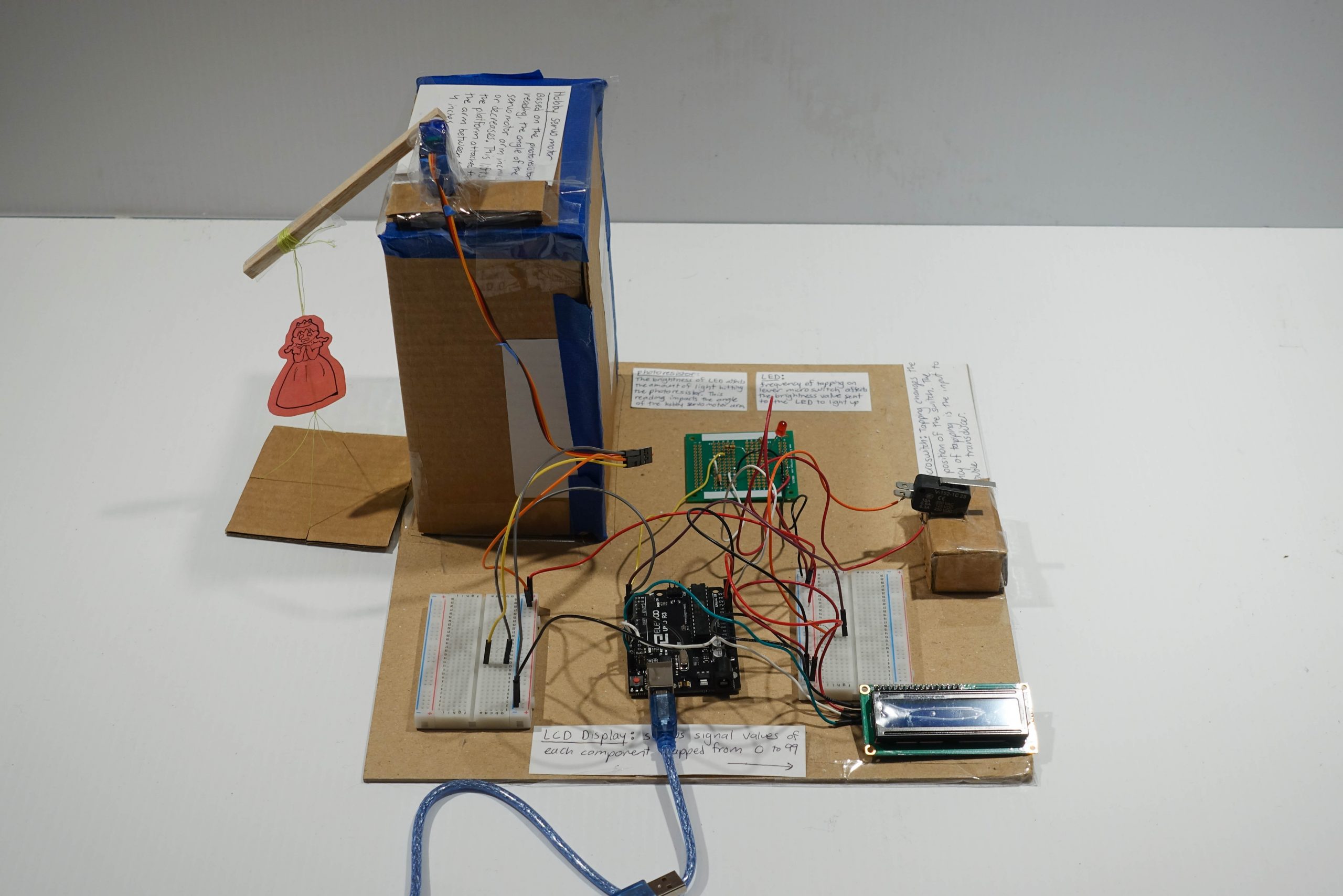
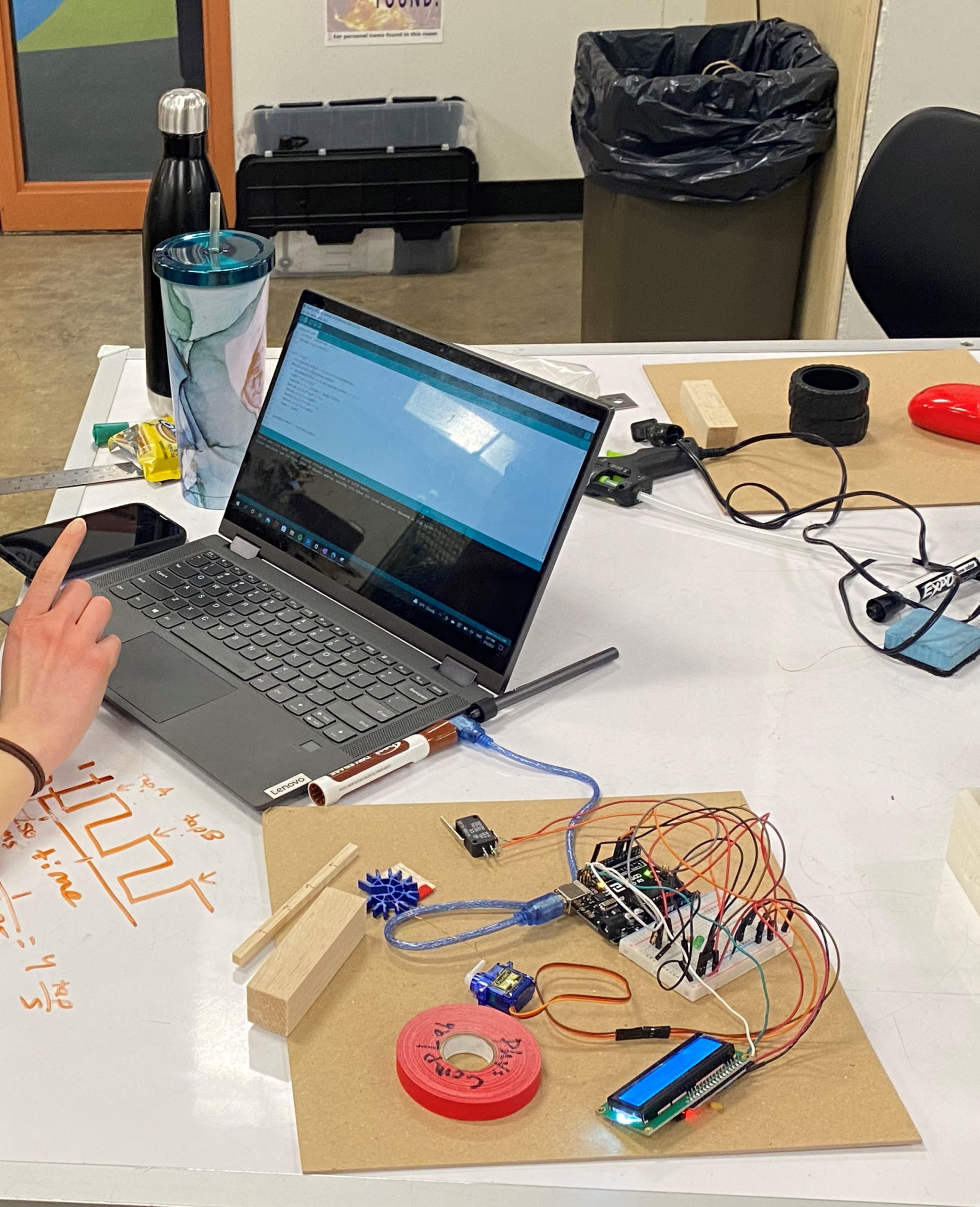
Overall photo of Lynn’s double transducer
Overall photo of Yongwen’s double transducer
Detail Photos:
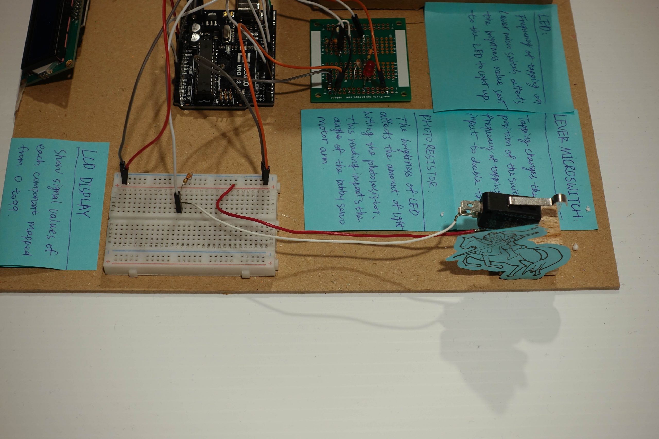
The lever switch connects to the first breadboard (the knight is trying to save the princess by tapping the switch)
Wiring details
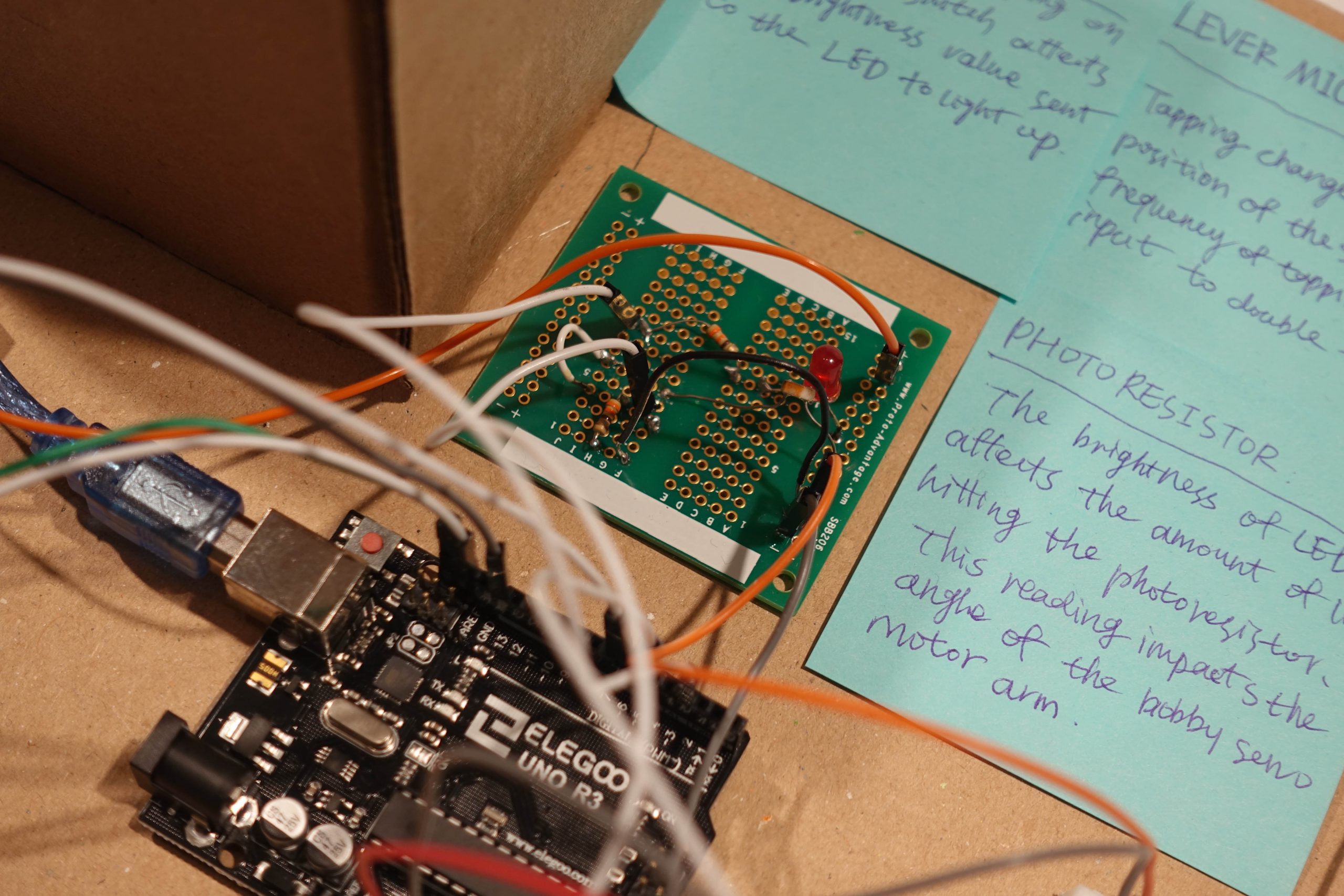
The photoresistor detects the LED brightness
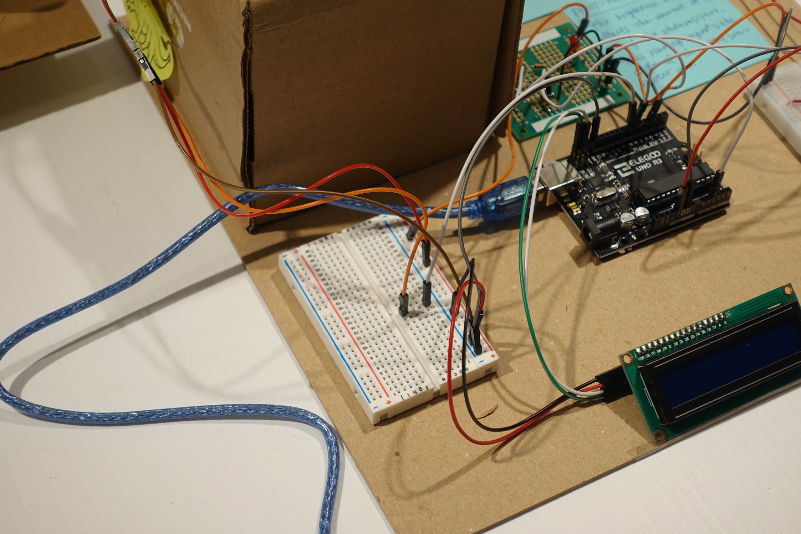
The second breadboard assembles the last wires to connect to the servo motor
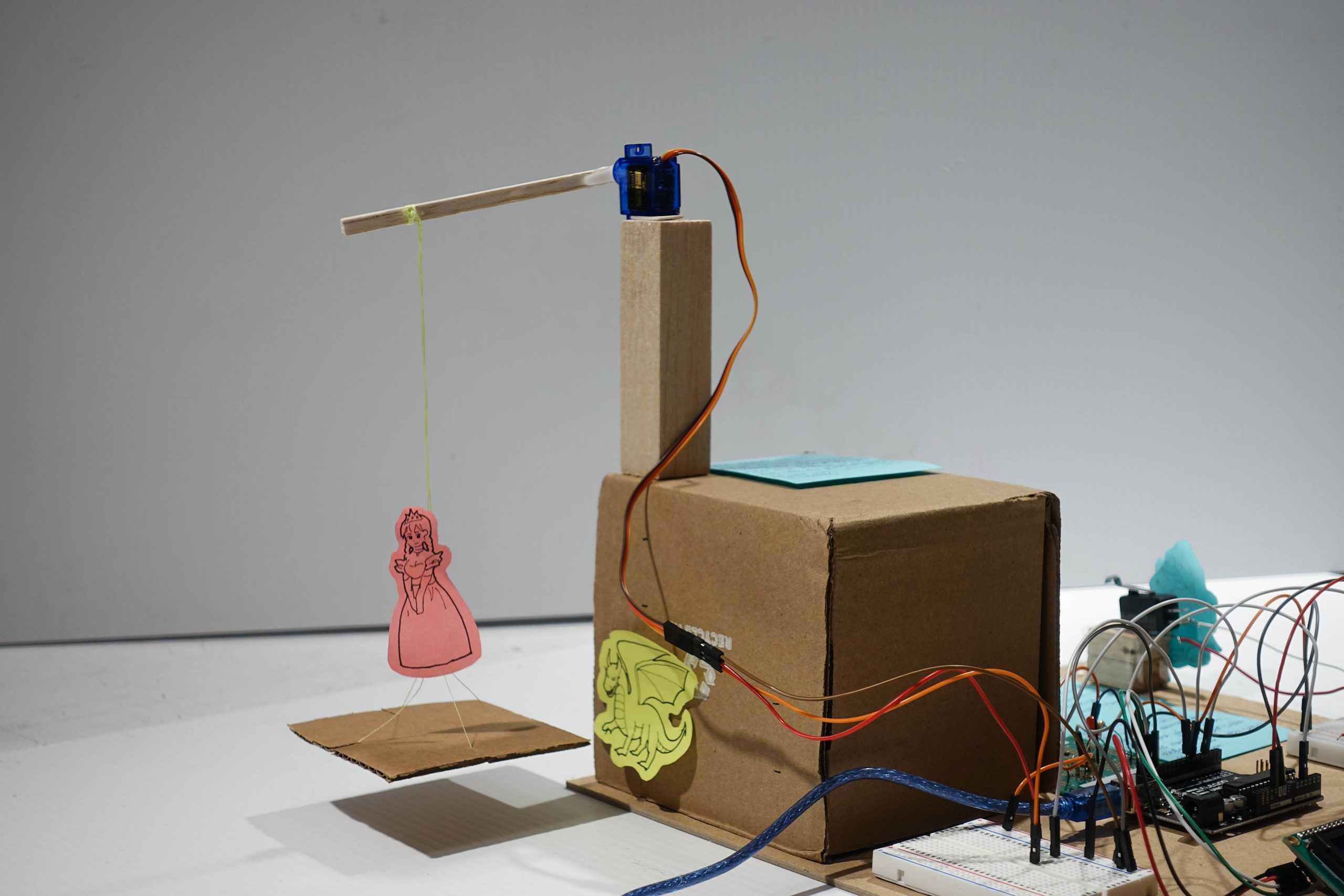
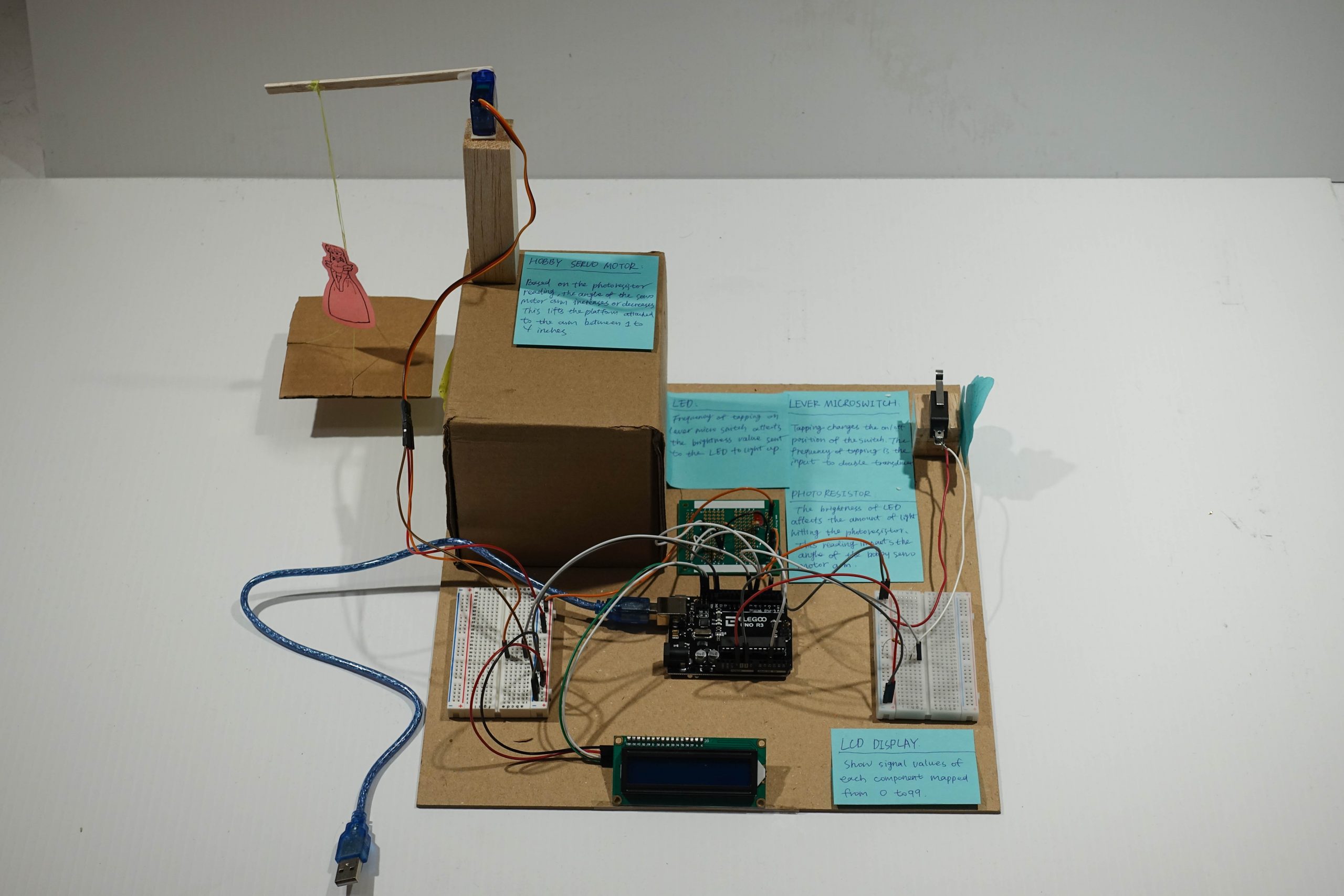
The arm is connected to the servo motor which can lift the platform up from 1 inch to 4 inches (the princess is being attacked by the dragon, please save her!)
Videos:
Video demonstration of Lynn’s double transducer.
Video demonstration of Yongwen’s double transducer.
Narrative Description:
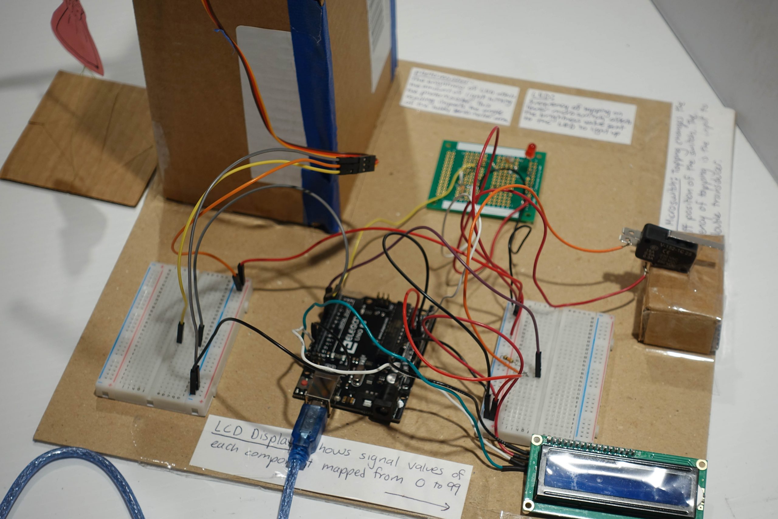
Our double transducer takes the tapping rate on the lever of the lever microswitch as an input. The speed of tapping on the lever translates to the brightness of the LED. The LED brightness is read by the photoresistor and dictates the position of a servo motor arm which lifts a princess cut-out up and down. An LCD screen will read out the tapping rate, LED brightness, photoresistor reading, and hobby servo motor arm position.
Discussion:
Overall, this project presented a valuable opportunity for us to become more familiar with coding in C and learn the electrical workings of different sensors and actuators. Both of us came in with different skill sets. Yongwen provided many creative ideas, such as turning our double transducer into a game of sorts where a princess was tied to the lifting arm of the servo motor and trying to escape a dragon cut-out at the bottom of the platform. She also provided insight into the most visually appealing layout of our final project. Lynn came in with some coding experience in python, so she was able to take a larger role in debugging our code when we were not getting the LCD readings or outputs we expected. By the time we completed the final product, we had both picked up on many new skills from each other.
Although we ran into challenges with almost every step of this project, this allowed us to learn a lot about the wiring and coding required to operate complex electrical circuits and devices. Working with the lever microswitch was one of the most challenging parts. One of the first decisions we had to make was how to perform our tapping rate calculations. Initially, we tried tracking the tapping rate as the number of taps each second but soon realized that we wanted the tapping rate to update faster than each second. Moving forward, we chose to track the tapping rate by measuring the time between taps so that the rate could update after each tap. We also ran into issues of our code outputting higher tapping rate readings than expected. After debugging, we realized that our code was considering each time the switch was in the “on” position as a tap. This meant that if the switch was held down for longer, a single long tap was read as multiple tapping events. We solved this issue by adding an “if statement” to only count a tap when there was a transition from the “off” to the “on” position. Even after fixing this in our code, we still were getting tapping rate values that were too high. After talking to Professor Zacharias, we learned that our switch could potentially be experiencing input “bouncing,” which is essentially electrical noise in the device that causes it to bounce between on/off states when tapped. We were able to “debounce” our input with a simple delay of 3 milliseconds after each switch reading to avoid reading the electrical noise. By taking the time to understand the intricacies of how the lever micro switch operates, we successfully created code that gave an accurate tapping rate reading.
If we had more time with this project, we would have chosen a more complex middle step over an LED and photoresistor. Since we were confident that we could get the LED output and photoresistor input working within the time frame of this project, we decided to go in that direction and focus our efforts on developing a code to get an accurate tapping rate reading for the lever microswitch and achieving a vertical lift with the angled servo motor arm. Now that we are more experienced in coding, soldering, and wiring, we could experiment with new sensors and actuators such as a magnetometer for magnetic field strength, an RGB sensor for color, or a buzzer to emit different sound pitches.
Progress Photos:
Lynn trying to find the best way to count the tapping rate for the input.
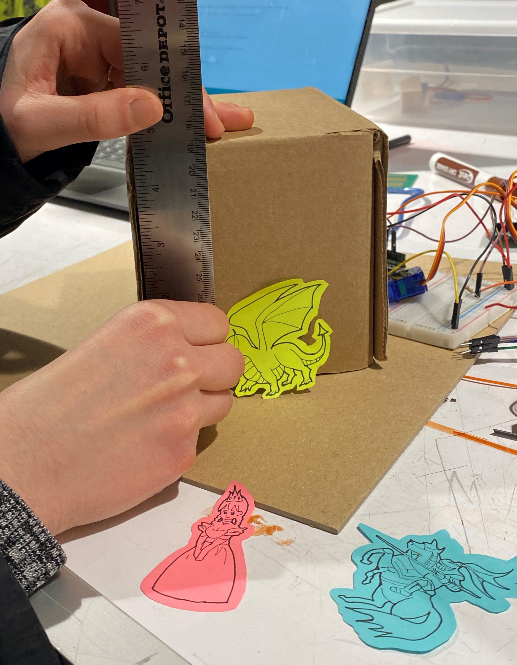
Measuring the correct distance for servo motor arm height of 1 inch to 4 inches.
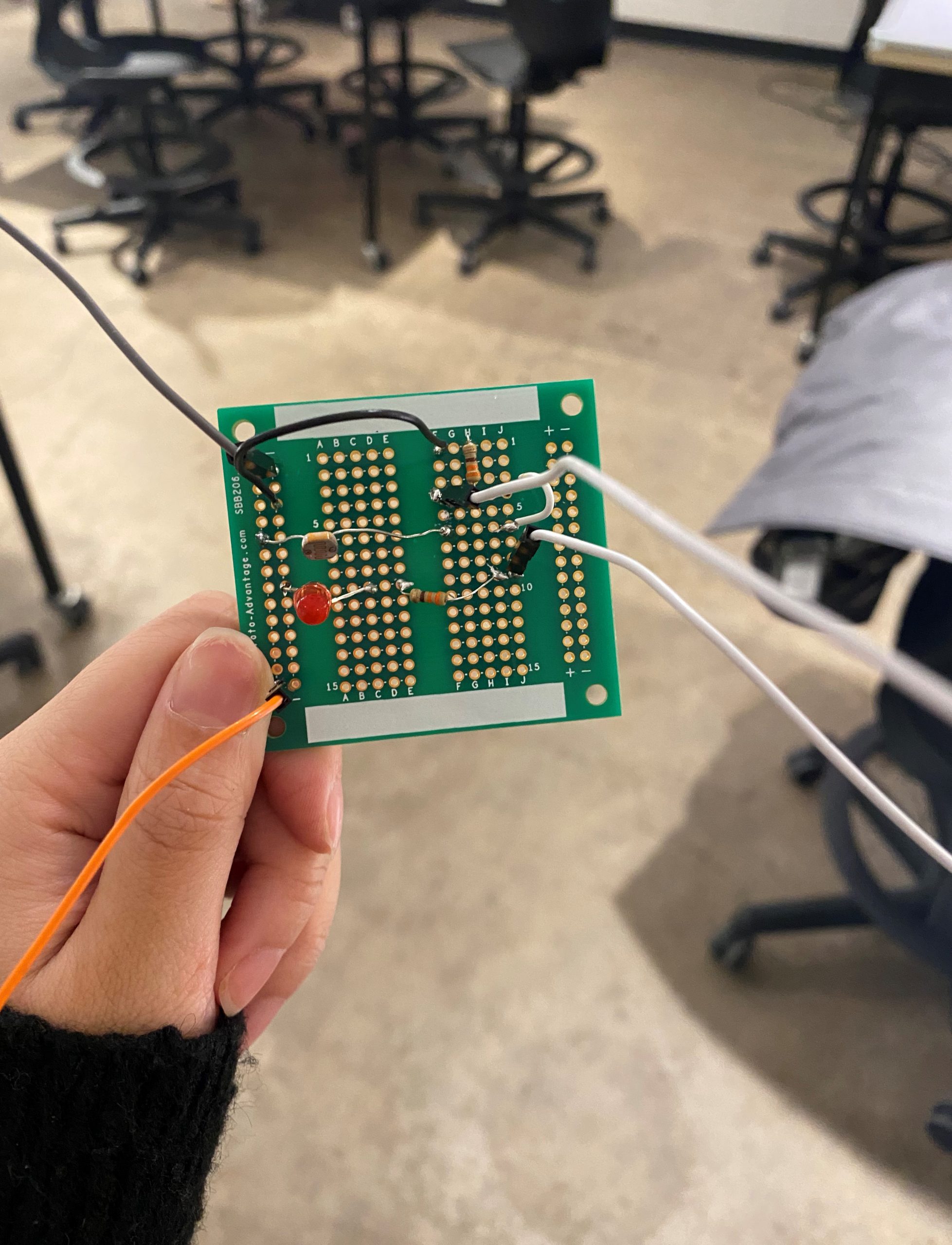
Our first attempt at soldering the LED and photoresistor to a breadboard.

Beginning to assemble our double transducer with the LCD display.
Block Diagram:
![]()
Electrical Schematic:
![]()
Code:
/* 60-223 Double Transducer
    Lynn Rushkin and Yongwen Dai

    Description: This code takes the tapping rate read by a lever microswitch and maps that to
                 the brightness of an LED. The level of light emitted from the LED is read by a
                 photoresistor which maps that value to the angle of a hobby servo motor arm.

    Pin mapping:
    Arduino pin | type   | description
    ------------|--------|-------------
    A2            input     Photoresistor that senses LED brightness
    6             input     Micro lever switch that reads on/off position of the switch
    3             output    LED pin for brightness
    7             output    hobby servo motor for arm movement

    The following sources were consulted to create our code:
    https://courses.ideate.cmu.edu/60-223/s2022/tutorials/servo
    https://courses.ideate.cmu.edu/60-223/s2022/tutorials/I2C-lcd
    https://courses.ideate.cmu.edu/60-223/s2022/tutorials/debouncing
    https://courses.ideate.cmu.edu/60-223/s2022/tutorials/button-and-switch
    Double Transducer: Frequency of Tapping to Distance to Beep Pitch
*/

#include <Wire.h>
#include <LiquidCrystal_I2C.h>
#include <Servo.h>
Servo liftingArm;
LiquidCrystal_I2C screen(0x3F, 16, 2);

//pin names
const int LEVERPIN = 6;
const int LEDPIN = 3;
const int PHOTOPIN = A2;
const int ARMPIN = 7;

//other variables
unsigned long taps = 0;
unsigned long lastSecond = 0;
unsigned long lastThirdSecond = 0;
float tapRate = 0;
int switchVal = 0;
int lightVal = 0;
int liftingVal = 0;
int photoVal = 0;
int currSwitchVal = 0;
int prevSwitchVal = 0;
unsigned long tapB = 0;
unsigned long tapA = 0;

//signal ranges
const int light_low = 0;
const int light_high = 255;
const int photo_low = 5;
const int photo_high = 630;
const int lift_low = 3;
const int lift_high = 75;

//Initialize the time between LCD display updates, and the timer itself.
const int LCDUPDATETIME = 250;
long prevDisplayTime = 0;


void setup() {
  pinMode(LEVERPIN, INPUT);
  pinMode(LEDPIN, OUTPUT);
  pinMode(PHOTOPIN, INPUT);
  liftingArm.attach(ARMPIN);
  Serial.begin(9600);
  //LCD Screen setup
  screen.init();
  screen.backlight();
}

void loop() {

  //Check current time.
  long currentTime = millis();
  currSwitchVal = digitalRead(6);

  /*when there is a transition in the switch position from off to on, count a tap
     tapB tracks the time of the most recent tap, and tapA tracks the time of the prior tap
  */
  if (currSwitchVal == 1 and prevSwitchVal == 0) {
    delay(3); //debounce input signal
    tapB = millis();
    tapRate = 1000.0 / (tapB - tapA);
    if (tapA == 0) {
      tapRate = 0;
    }
    tapA = tapB;
    //set 3 taps/sec as the maximum tapping rate
    if (tapRate > 3) {
      tapRate = 3;
    }
  }

  //set tapping rate to 0 if over a second has passed since the last tap
  if (millis () - tapA > 1000) {
    tapRate = 0;
  }
  prevSwitchVal = currSwitchVal;

  //update the LED brightness and servo motor arm height every second based on the tapping rate
  if (millis() - lastSecond >= 100) {
    lightVal = map(tapRate * 10, 0, 3 * 10, light_low, light_high); //map tapping rate to a brightness value
    analogWrite(LEDPIN, lightVal); //tell LED how bright it should be
    photoVal = analogRead(PHOTOPIN); //photoresistor sends brightness value to computer
    liftingVal = map(photoVal, photo_low, photo_high, lift_low, lift_high); //map brightness value to angle of arm
    liftingArm.write(liftingVal); //tells servo motor arm how high to lift
    delay(10);
    lastSecond = millis();
  }

  //Update LCD display every 250 milliseconds.
  if (currentTime - prevDisplayTime >= LCDUPDATETIME) {
    screen.clear();

    //Map tap rate to a range of 0-99 on LCD display.
    int newtapRate = map(tapRate * 10, 0, 3 * 10, 0, 99);
    screen.home();
    screen.print("i:");
    screen.print(newtapRate);

    //Map brightness value to a range of 0-99 on LCD display.
    int newlightVal = map(lightVal, light_low, light_high, 0, 99);
    screen.setCursor(6, 0);
    screen.print("m:");
    screen.print(newlightVal);

    //Map photoresistor values to a range of 0-99 on LCD display.
    int newphotoVal = map(photoVal, photo_low, photo_high, 0, 99);
    screen.setCursor(8, 1);
    screen.print(newphotoVal);

    //Map height values to a range of 0-99 on LCD display.
    int newliftingVal = map(liftingVal, lift_low, lift_high, 0, 99);
    screen.setCursor(12, 1);
    screen.print("o:");
    screen.print(newliftingVal);

    prevDisplayTime = currentTime;

  }
}