Project 1: A Double Transducer
Project schedule
| Element | Date |
|---|---|
| Project introduction | Wednesday, Jan. 25th |
| Ideation | Monday, Jan. 30th |
| Final critique | Wednesday, Feb. 8th |
| Documentation | Wednesday, Feb. 15th |
| Feedback | due to you by Wednesday, Feb. 22nd |
Some definitions
The good people at the Oxford English Dictionary tell us that a transducer is “any device by which variations in one physical quantity (e.g. pressure, brightness) are quantitatively converted into variations in another (e.g. voltage, position).”
For this assignment, we’ll refer to a realm of related “physical quantities” as a domain. For instance, “sound” is the domain that encompasses things that either produce or sense vibrations traveling through a medium, and the domain “light” includes things that produce light (like LEDs) as well as light sensors.
Our definition
A transducer is for us simply some device which changes an input in one domain (such as light, sound, vibration, magnetic field, etc.) into an output in another domain.
For instance:
- a light bulb converts electrical power into heat and light
- a solar panel converts light into electrical power
- a speaker converts electrical power into sound
- a microphone converts sound into electrical power
- an electric car converts electrical power into movement
- a compass converts a magnetic field into a rotational angle
- you convert food energy into learning!
The Double Transducer
The goal of this project is for each team to build a device which reads some input signal in a domain, then converts it into a signal in another domain, reads that second signal, and finally outputs a third signal, which is in a third different domain. Whereas a single transducer would change a signal from one domain to another, a “double transducer” will do that process twice in a row.
Our goal will be to “chain” as many of these transducers together as possible: ideally, at the crit in class, we’ll be able to see a single signal flow through each of the machines you make, in a row, head to tail. This will require some class-wide coordination—that’s why your input and output domains are being assigned.
Examples
A light-to-movement-to-sound machine
The user’s description of this double transducer might be: “When the light in the room gets brighter, a little motor moves and turns a little knob, and then the sound coming out of a speaker gets louder. When the light in the room gets dimmer, the opposite happens, and the sound gets quieter.”
To explain this device from its creator’s perspective:
- The first transducer takes as an input the light level in the room. It drives the position of a servo motor as its output. (A servo motor is a rotational motor whose position can be controlled by the Arduino.) This transducer changes an input signal in the “light” domain to an output in the “mechanical/position” domain.
- The second transducer then reads the “mechanical/position” state of the servo motor output using a potentiometer. It then uses the potentiometer’s value to adjust the volume level of a speaker, which is a “sound” output.
The chain of information through this double transducer could be shown like this:

light (sensed by a photocell) ⇒ mechanical position (driven by a motor)
→ mechanical position (sensed by a potentiometer) ⇒ sound (produced by a speaker)
Note that the ⇒ double arrows above show steps where the signal has been transduced across domains, and the → single arrow shows a step where an output in one domain is being read as an input in that same domain.
A position-to-light-to-vibration machine
A user’s description: “When the machine gets closer to an object, it shines less light on a sensor, and then a small motor vibrates more. When the machine gets farther from an object, it shines more light on a sensor, and the motor vibrates less.”
The two transducers:
- The first transducer uses an ultrasonic ranger to detect the proximity of an object to the machine. When it detects a closer object, it makes an LED get dimmer; when it detects something farther away, it gets brighter.
- The second transducer measures the light coming off of that LED. When it sees a brighter light, it makes a small vibration motor move less, and when it sees a dimmer light, it makes the motor vibrate more.
The information chain of this double transducer could be shown like this:

position (detected by an ultrasonic ranger) ⇒ light (produced by an LED)
→ light (measured by a photocell) ⇒ mechanical vibration (produced by a vibratory motor)
Anti-example: a temperature-to-sound-to-temperature machine
This is an example of a transducer that does not satisfy this assignment’s prompt.
A user’s description: “When the thermometer detects a higher temperature, it makes a speaker get louder. When the microphone hears that louder sound, it turns on a heater. On the other hand, when the thermometer detects a lower temperature, the speaker gets quieter, and the heater turns down too.”
The problem here is that the input domain of the first transducer (which is temperature⇒sound) is the same as the output domain of the second one (which is sound⇒temperature). All three domains in the machine must be different. If the output of the second transducer were instead something like a laser changing brightness, then this would satisfy the assignment.
Ideation
15 points
due Monday, Jan. 30th at the start of class
Prior to class, work with your partner(s) to come up with three ideas for what you’d like to make for this project. Flesh out each idea a bit and provide for each idea:
- a few sentences of narrative description,
- a mechanical/physical sketch of your proposed build,
- a functional block diagram, and
- an electrical schematic.
The functional block diagram and electrical schematic should be produced using our customized version of draw.io. The mechanical/physical sketches can be done on a computer using CAD software, or drawn by hand on paper, or however you’d like.
Note that you may find your functional block diagram looks a bit different than those we have seen so far: if an element acts as both an input and an output, what would that look like? And if one element’s output is the direct input to another (as this assignment requires), how should you diagram that? Consider these questions as you’re doing your drawings, and don’t be afraid to branch out from the examples you’ve seen so far; this part of the assignment is meant to stretch your thinking a bit.
You should generate a Google Doc to submit your ideation. Use at least one page per idea. We’ll discuss them in class and you’ll get written feedback afterwards as well.
Submit a link to your Google Doc via the “Project ideation” assignment in Project 1.
Ideation rubric
| Grade range | Ideation qualities |
|---|---|
| 11–15 | At least three pages of ideation submission, each of which contains a few sentences of narrative descriptino, a mechanical/physical sketch, a functional block diagram, and a reasonable attempt at an electrical schematic |
| 6–10 | Partial fulfillment of the above requirements, or fewer than three ideas submitted |
| 0–5 | Ideation very incomplete or missing |
Final deliverable
due Wednesday, Feb. 15th, at the start of class
Each group will design a Double Transducer together, but each student will build their own copy of that Double Transducer (so each team produces two physical Double Transducers). On the final crit day, we’ll have the opportunity to try each teammate’s transducer as part of the class chain.
The deliverable is graded based on its Technical Proficiency (35 points available) as well as its Creativity, Novelty, and Demonstration of Original Thinking (5 points available).
Creativity, Novelty, and Demonstration of Original Thinking
5 points
Does your project do something interesting? Does it use a part, or parts, you found in the Phys Comp Lab in a strange/funny/neat way? Is it intriguing?
You are welcome to use entirely off-the-shelf parts for your project, but if you want to stretch a bit further and do something more exploratory, such as building your own sensor, actuator, or transducer, that’s a great way to earn some additional points in this section. Here’s an example of a prior project that did this especially well: they built their own potentiometer which was motor-actuated. Other projects have included little “stories” as part of their machine, e.g. little cartoon characters or action figures getting involved in the device. Feel free to go in whatever creative direction seems interesting to you!
Creativity, Novelty, and Demonstration of Original Thinking rubric
| Grade range | Creativity, Novelty, and Demonstration of Original Thinking qualities |
|---|---|
| 4–5 | Novel, interesting, or creative use of sensors, actuators, or other aspects of the project, e.g.: building your own sensor or actuator, or incorporating some little storytelling element into your project fabrication |
| 2–3 | Somewhat creative execution demonstrated in some dimension, with some novel or creative element(s) |
| 0–1 | Strictly by-the-book design, fabrication, and execution without novel or creative element(s) |
Technical Proficiency
Signal flows properly through transducer
15 points
This is the technical core of the project. A signal should flow through your project (i.e. from input, through the middle step, and to the final output) with little delay. It’s ok if it takes a second or so for the signal to get through, but it shouldn’t be much more than that.
The input is continuous and the output should be continuous, too—so if the input is a potentiometer, as it’s turned throughout its range, the output should be continuously varying along its range. However, a “low” input can produce a “high” output and vice versa if you like.
Technical Proficiency rubric
| Grade range | Technical Proficiency qualities |
|---|---|
| 12–15 | An input signal is smoothly transformed into an output through the action of the machine. |
| 7–11 | At least one of the two transducer stages works very well, though the other one might not. Because of this, the signal does not make it smoothly all the way through the machine. |
| 3–6 | A signal makes it through the machine, but it’s either turned into a binary output or it’s otherwise broken into very few (~4 or fewer) steps. |
| 0–2 | Little or no portion of the device works meaningfully. |
Physical Arrangement
2 points
Your transducer should be physically situated on a piece of chipboard (which will be given to you in class), with its input sensor elevated 1” off the surface centered on the left edge, and its output delivered 1” off the surface centered on the right edge. The middle step of the device can be arranged however you’d like. (The purpose of this standardization is to allow for multiple transducers to be placed right next to each other, to physically move a signal along the chain.)

It is acceptable for your device to need external power, but battery power is preferable if possible. The LCD display should be centered on the side facing the user (i.e. with the input to its left and output to its right).
Physical Arrangement rubric
| Grade range | Physical Arrangement qualities |
|---|---|
| 2 | Input and output are at opposite ends of board as specified; LCD screen is in correct location |
| 1 | At least one element is in the right location |
| 0 | Nothing’s in the right place! |
Labeling
3 points
The different steps of transduction should be labeled in writing on the cardboard surface (or other paper/etc. affixed to the surface) so that your classmates and others can look at your transducer and read what each step is doing. The labels (which may be hand-written) should name and very briefly describe each sensor or actuator, e.g.:
Photoresistor
This device’s electrical resistance changes based on the amount of light hitting it.
or
Servo motor
The Arduino transmits a signal to this device to command it to move its output arm to a specific degree position.
Labeling rubric
| Grade range | Labeling qualities |
|---|---|
| 3 | Clear, legible, complete labeling |
| 1–2 | Less-clear, less-legible, or incomplete labeling |
| 0 | No labeling |
Status display
10 points
You should employ an LCD display, preferably 16×2 though 20×4 is also acceptable, to give any viewer an active update of the status of both of the sensors as well as both of the actuators. The displayed value of each sensor’s or actuator’s state should be normalized to a range of 0–99 for ease of reading (for instance: though a potentiometer may have actual values 0–1023 on the Arduino, you should remap that range to a minimum 0 and maximum 99). The display should follow a particular formatting scheme which would display like so:
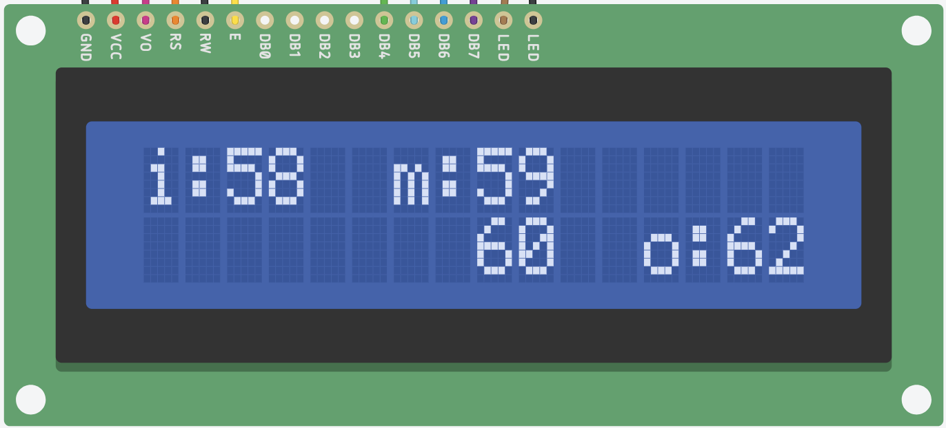
Explanation of each of the values displayed:
- The input sensor’s value is on the upper left of the screen (
i:58in this example) - The middle-step actuator value is in the center top of the screen (
m:59in this example) - The middle-step sensor value is in the center bottom of the screen (
60in this example) - The output actuator’s value is in the lower right of the screen (
o:62in this example)
Further notes on the display:
- Please see the I²C LCD tutorial, and in particular the example code included there, for information about how to align text on the screen in particular positions.
- The
istands for “input,” themstands for “middle step,” and theostands for “output.” We have to use such short abbreviations for everything because the display is only 16 characters wide! - The LCD display should update 4–10 times per second. If you try to update it very quickly (like, every
loop()) it will flash very fast and be quite difficult to read. We’ll discuss in class how to make something happen on a schedule (like 4 times per second, for instance) with a software structure called “event loop programming.”
Status display rubric
| Grade range | Status display qualities |
|---|---|
| 8–10 | Display text is positioned as specified; display updates 4–10 times/second; display values are in 0–99 range |
| 4–7 | Some of above requirements are met, but not all |
| 0–3 | Display is barely functioning, or not at all |
Soldered connections for the middle step
5 points
Please make the electrical connections for your middle step of the transduction more “solid” than they would otherwise be by using properly soldered joints for these parts. (This means that whatever wires come out of those parts should be soldered rather than plugged into a breadboard.)
The Canvas module on soldering contains a series of videos teaching you various basic techniques.
Soldered connections rubric
| Grade range | Soldered connections qualities |
|---|---|
| 4–5 | All middle-step connections are soldered as specified |
| 2–3 | Some soldering, but some middle-step connections aren’t soldered |
| 0–1 | Little or no soldering of middle-step connections |
Groups
You’ll be assigned a partner for this project; pairings will be announced in class on Jan. 25th. If you are becoming frustrated or feel like you’re not going to be able to succeed in getting a project together with your assigned partner, speak with Zach as soon as possible so we can sort things out.
You will also be assigned (with your partner) a particular input and output domain for the machine you make; the third (middle) domain is entirely up to you.
Scope and Expectations
This assignment is given early in the semester, when there hasn’t been much time for technical learning. You’ll just be getting comfortable with simple circuits by the time the project comes due, and you’re not expected to build something very complex electronically or mechanically. Instead, you’re expected to think creatively and build something interesting that actually functions to transduce the assigned input signal to the assigned output signal.
For this project it is preferable to scope your work pragmatically and finish with a functioning machine rather than aiming for a very sophisticated outcome and falling short. Give yourself plenty of time to fail and iterate before the final crit!
It’s ok for your machine to look somewhat aesthetically sloppy, so long as it works—but if you can keep your wires/electronics/etc. on the neater side of things, it will make it easier and clearer for onlookers to understand the functioning. Build it out of cardboard, tape, straws, and hot glue if you want! Low-cost and easy-to-use materials are great and expected.
Documentation
due Wednesday, Feb. 15th at the start of class
Why do you submit documentation?
The Arduino project was born, after some twists and turns, out of an Italian masters student’s thesis.1 He could have, one imagines, kept all those ideas to himself, started up a little factory, and sold them for €50 and called it a day. But the project has grown into a worldwide thing of beauty because the hardware designs (how to build an Arduino) and all of the underlying software (how to program one) are “open-sourced.” This means that anybody who wants to can see the community’s work and make their own version. Maybe even improve it themselves, and then suggest that their improvement might be something the community as a whole wants to adopt. Don’t believe me? Look at all these people contributing to the project’s Github page.
Think of how great it is for someone to see your cool project, get inspired, and build on it to make their own customized version. The answer is: very great! Having stood on the shoulders of others in the world of people making things, you can begin to return the favor by sharing the interesting ideas and technical insights you had.
Finally, we in IDeATe are interested in encouraging an introspective inquiry into your own process of ideation, creation, and revision. Just as writing an essay helps you understand your own argument on a topic better, documenting your own creative process will help you understand your creativity better. Documentation gives you insight to see what you got hung up on and what steps you wish you’d lingered on more. It opens a window onto your own process.
What to submit (documentation content requirements)
If you have any questions about the submissions requirements, or run into technical problems, be sure to contact the instructor before the due date.
Each documentation submission must consist of at least:
-
A “featured image” that is a good overall view of the project. This image will show up above the title of your project in the overview page. This image should be one of final project images described below, or a cropped subset of one of them. Select the featured image by clicking on “set featured image” in the right column of the post editing page.
-
The project title in the format “Double Transducer: Your Project’s Name Here.”
-
Decent images of the final projects. If it’s possible for you to take higher-quality image, like using a DSLR (here’s the class DSLR photography guide), that’s fine; but camera phone pictures are ok, too.
At least four images:- Overall photo for proportion and scale (one per team member)
- Detail photos of any part that you’d like to highlight (two to five between the team members)
- Brief movie in
.mp4format to embed in the documentation page which shows the machine working, i.e. reading an input, passing the data internally, and then driving an output. Make sure the LCD screen’s output is visible in the movie so we can all see what the Arduino is thinking. (one per team member)
To add an
.mp4video to your post, upload the file to the Media Library, and under the “Attachment Display Settings” dropdown, select “Embed Media Player” before clicking “Insert into post.” This will ensure that the video itself, rather than a link to the file, appears in your documentation.
Each image should be captioned. (To add captions in WordPress: click on an image, click on the pencil icon to edit it, write a caption, and click “update.”) The captions serve to explain both what the viewer is looking at, as well as elucidating some of the operating details of the object.
In addition, if appropriate, add
alt textto your images.Alt textis a feature ofHTMLthat helps people who can’t see your images to understand what is in them. If your caption explains what’s happening in a picture, for instance: “This small grey box with red buttons is the main user interface,” then there’s no need to addalt text, because it would be redundant with the caption. If, however, your caption doesn’t explain the contents of the image well, for instance a caption like “The machine working,” you can addalt textvery easily in WordPress: click on an image, click the edit (pencil) icon, and enter your text into the “Alternative Text” area at the top of the dialogue. Here is some useful guidance about how to write goodalt text.
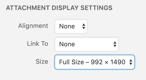
When uploading still images, in the “Add Media” window, select “Full Size” under the “Attachment Display Settings” header, as shown below. (If you choose a smaller size, your images will be downsampled, potentially with very ugly and destructive results.)
-
Simple narrative description (one per team) of the thing and usual operation of the thing—the type of plain and straightforward description that you might write in a letter to a child to explain what you had made. Free of judgment and totally literal and straightforward. Try to use as little technical language as possible. (E.g. “A white plastic box has a switch on the top side. When the user turns it on, a green LED flashes five times showing that the system is ready. A small white flag waves back and forth.”) For a study in the art of using simple language, see Randall Munroe’s wonderful Up Goer Five. To use a simple-language filter yourself, try the Up-Goer Five text editor.
-
Four progress images (two per student), each of which could be a step or misstep that happened along the development process, and each with a caption that’s at least a sentence or two long. These images may capture decision points, especially interesting or illustrative mistakes, or other mileposts along the way. The idea is that these medium-quality images (though good pictures work too) are taken along the way to document progress. Sometimes you might understand these as being moments-that-matter only in retrospect! The safe route, therefore, is to snap lots of photos as you go along for later review.
-
Discussion (one per team) pertaining to process and outcome. For instance, what was easy, what was hard, what did you learn? What little tweak, in retrospect, would’ve changed the direction entirely? This is an opportunity for you to reflect on your creative and technical growth through the project, and think about what growth you want to aim for next. This shouldn’t be a recital of your process, but rather a meaningful reflection, 2–4 paragraphs in length.
-
Functional block diagram and schematic (one per team), drawn in draw.io using the conventions we discuss in class and recorded on the Schematics and Functional Block Diagrams page. It’s best to use the
SVGfile format for these. -
Code submission (one per team), embedded into the project page, and optionally also with a Github or other version control service public-facing link. Your code should be reasonably commented throughout so that people other than you (the author) can better understand it. You don’t need to explain every single line—that would be overkill—but leave useful notes in a reasonable measure. Write a comment block at the top of the code including:
- the project title,
- (optionally) your names,
- a description (short or long) of what the code does,
- a pin mapping table that would be useful to somebody else trying to recreate your work (this is a simple table that lists all of the connections to the Arduino pins),
- appropriate credit to any other person’s/project’s code that you incorporated into your project, and
- (optionally) a license notice (i.e. copyright, CC BY-SA 4.0, the MIT License, release it to the public domain, or just follow your heart). If you have written code that you wish to keep strictly proprietary for any reason, please speak with the instructor about an exception to this documentation requirement.
Make sure that your final code as it appears on the public-facing post is correct and will compile!
To embed the code properly: on the WordPress “Edit Post” page, move your cursor to where the code should be inserted in your post. Click the “Code Insert” button in the toolbar above the post (it is marked
{…}). For Language, selectC. Paste the code—properly indented!!—into the window, and click OK.
How to submit (WordPress instructions)
All documentation is submitted by making a post on the course WordPress site.
For Project 1: A Double Transducer, make a post with the title in the format “Double Transducer: Your Project’s Name Here.” The post should have all group members added as authors. On the right side of the page where you compose your post, under “Categories” select “Project 1.”
Ordering parts
If you need parts that aren’t available in IDeATe Lending or in Phys Comp stock, the class budget may be able to make the purchase for you. As soon as you know you’ll need a part purchased, email Zach with these details:
- Part name
- A link to the suggested purchase site
- Cost per unit
- Number of units needed
- Brief explanation of why you need this part
- Any other relevant notes
Here’s a link to make the request a bit easier.
Feedback rubric
Credit is allocated as follows:
- 15% Ideation
- 40% Final critique
- 35% Technical proficiency
- 15% Signal flows properly through transducer
- 2% Physical arrangement
- 3% Labeling
- 10% Status display
- 5% Soldered connections
- 5% Creativity, novelty, and demonstration of original thinking
- 35% Technical proficiency
- 45% Documentation
- 15% Images
- 15% Writing (narrative and discussion sections)
- 10% Schematic and block diagram
- 5% Code
Footnotes:
-
This is actually complicated and contentious. See this account from that masters student, Hernando Barragán, to get his side of the story. ↩
