
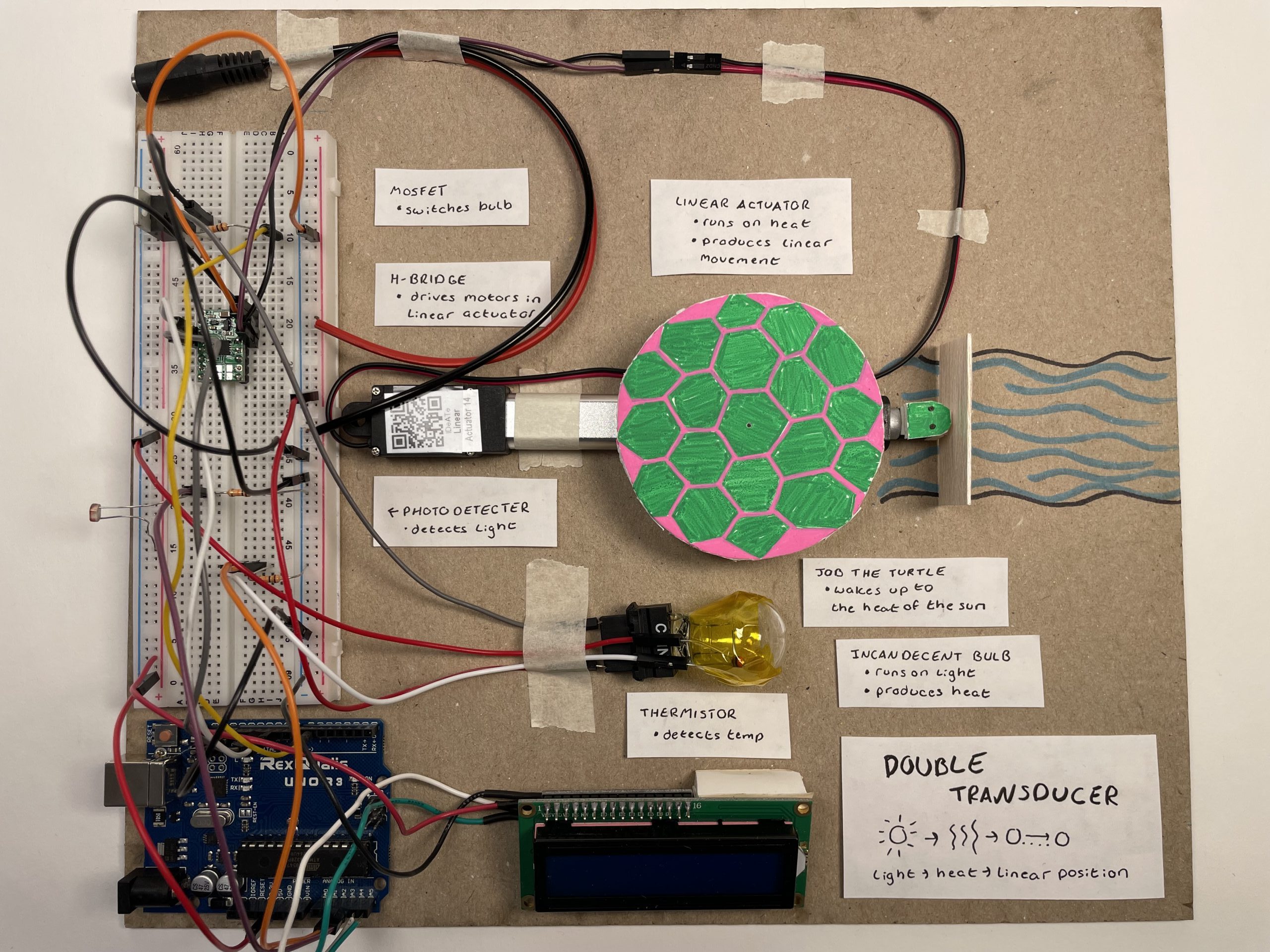
This is the final setup of Evie’s Sunshine machine
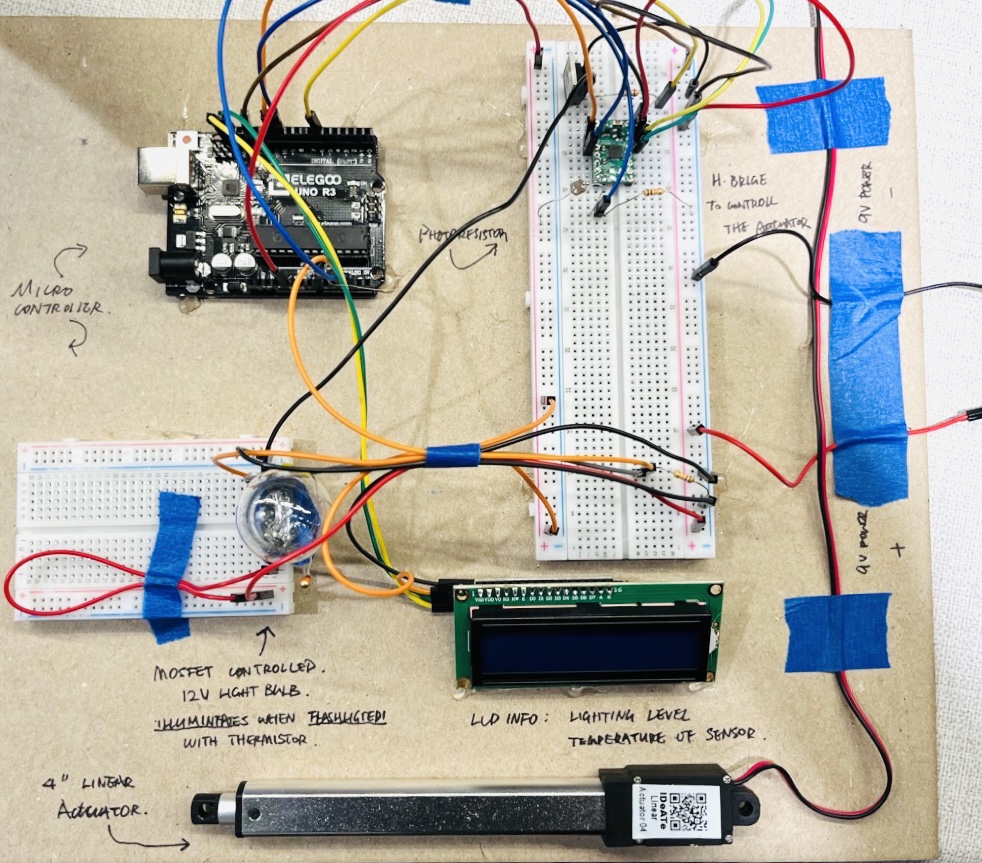
Finalized setup of Dongtao’s sunshine machine (without Casey)
Project Overview
The “Sunshine Lovers” is a machine that transduces light input into a linear position through an intermediate step.
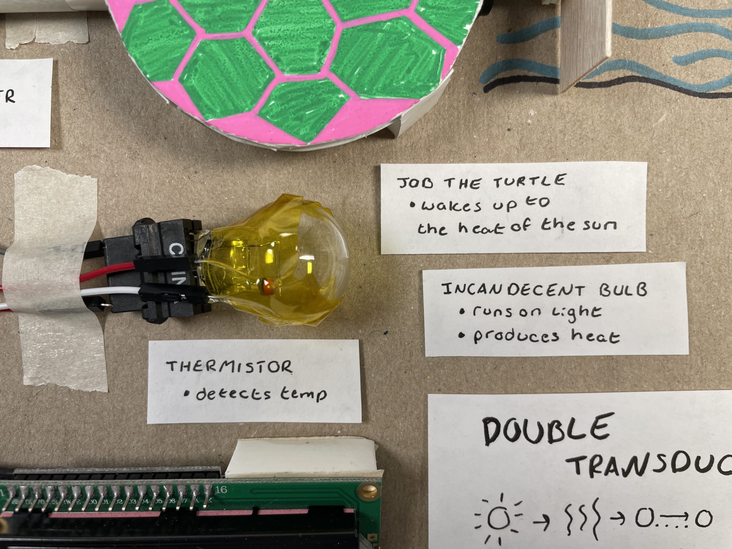
here you can see the thermistor taped to the incandescent bulb to read heat (evie).
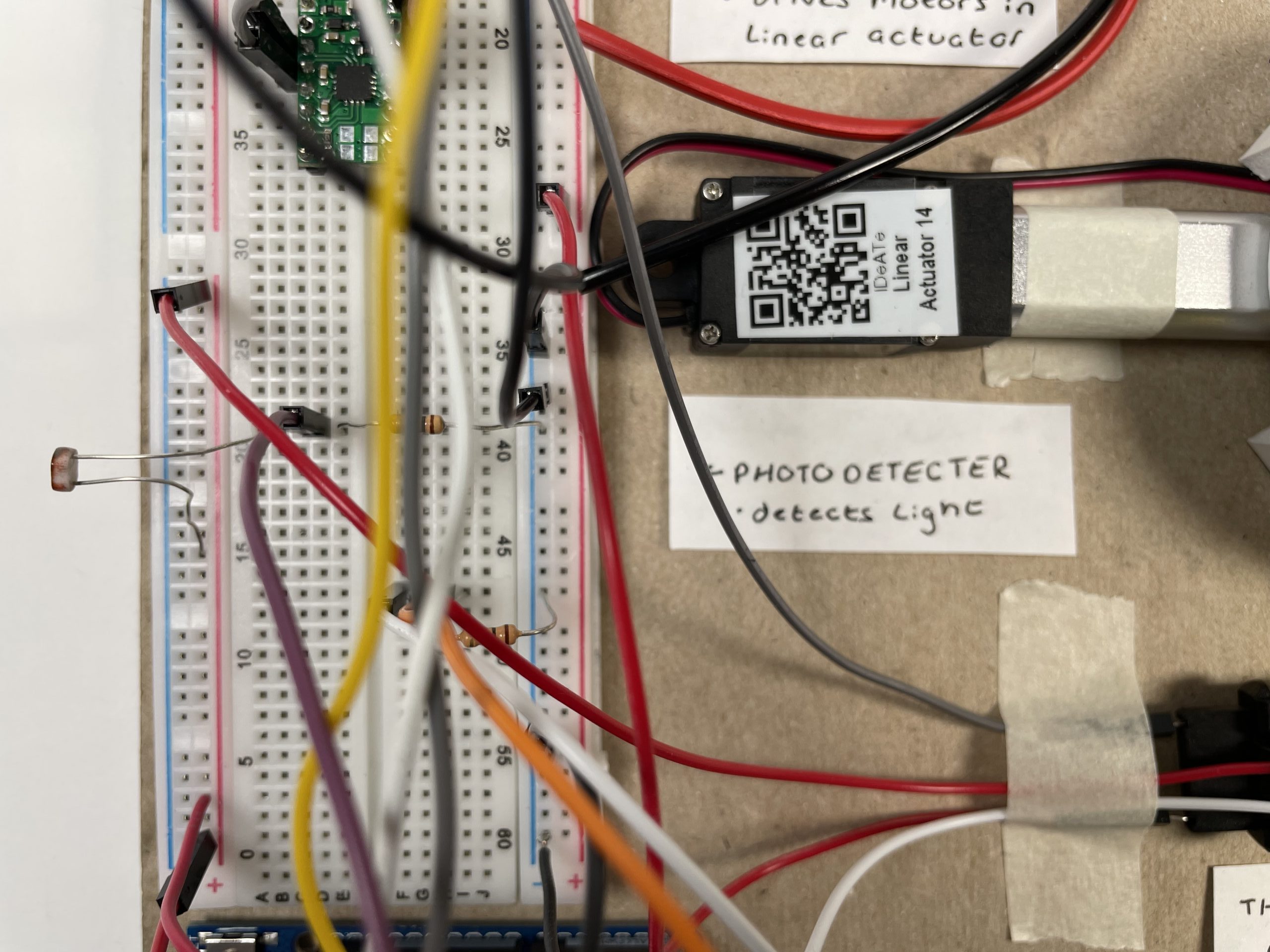
Here you can see the photoresistor at the end of the board which is our main input. (evie)
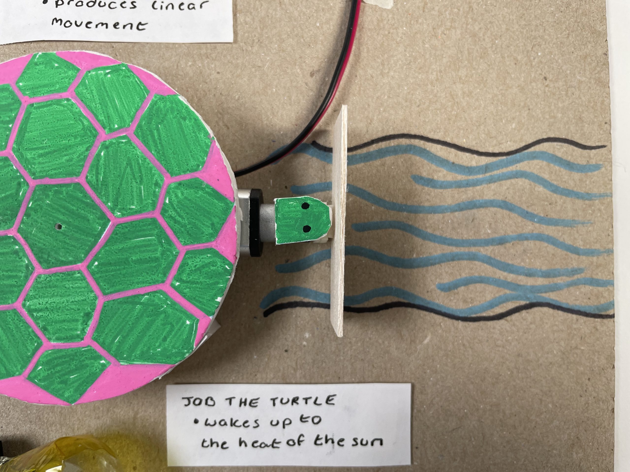
This is Job the turtle who’s head it attached to a linear actuator.
Working Demo 1 – The Turtle Job
Working Demo 2 – The Casey Bro
Process
Narrative description
Our double Transducer takes in light and transforms it to a linear position. The photoresistor reads light and the value of light is transformed to a value of heat created by an incandescent bulb. A thermistor reads the heat on the incandescent bulb and then sends the value of heat to a linear actuator. In Evie’s the linear actuator works as a turtle, named Job, who wakes up to the heat of the sun and then begins to swim downstream. In Dongtao’s machine, Casey brings a happy face that moves to indicate joy. The linear actuator should resemble the amount of light from the beginning of the chain.
-
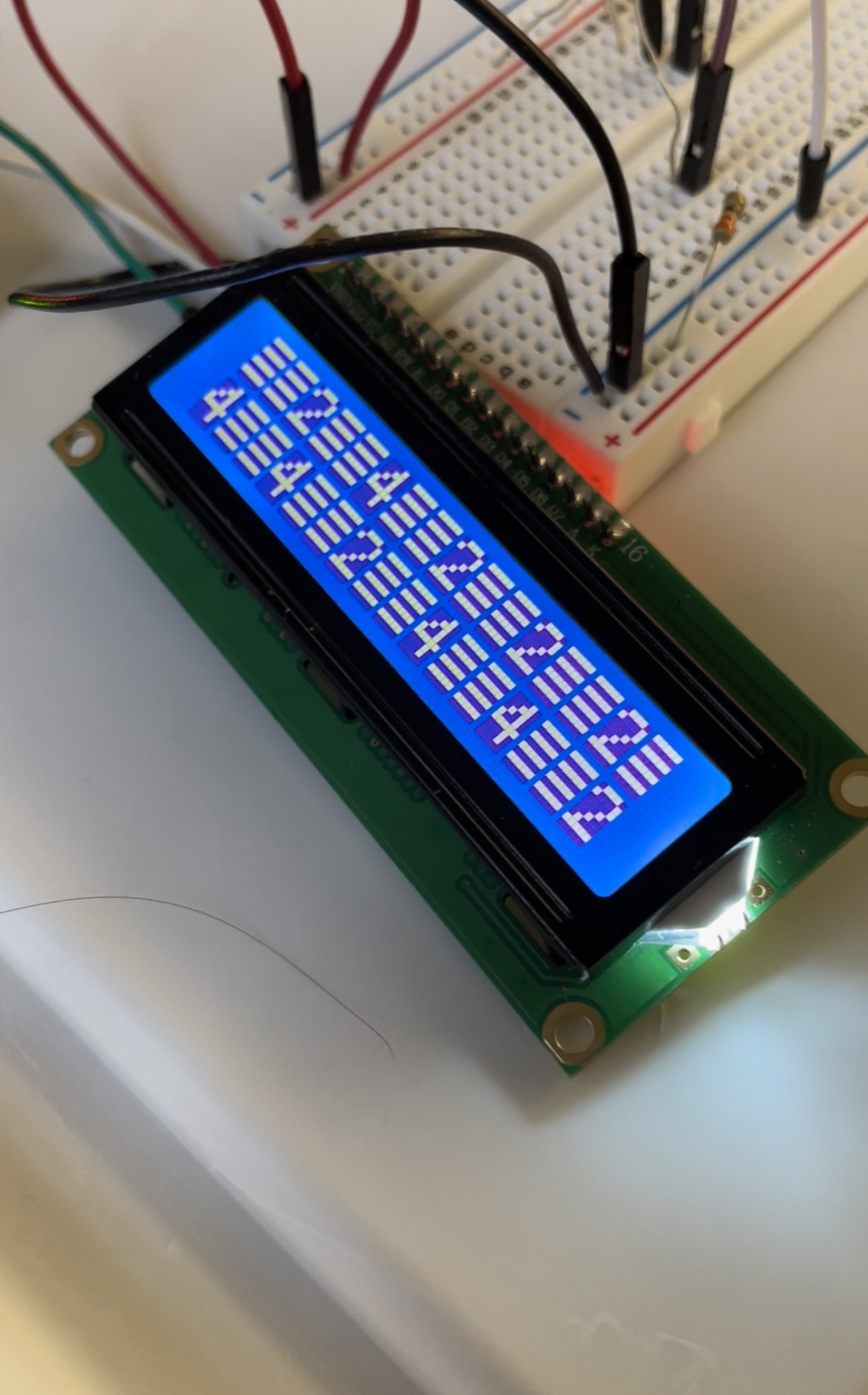
This is our first attempt at coding the LCD screen you can see how the data is coming out as a string with two spaces between. (evie)
We tested a temperature detector to see if it was more or less accurate to a thermistor, we found that it was much less (evie)
-
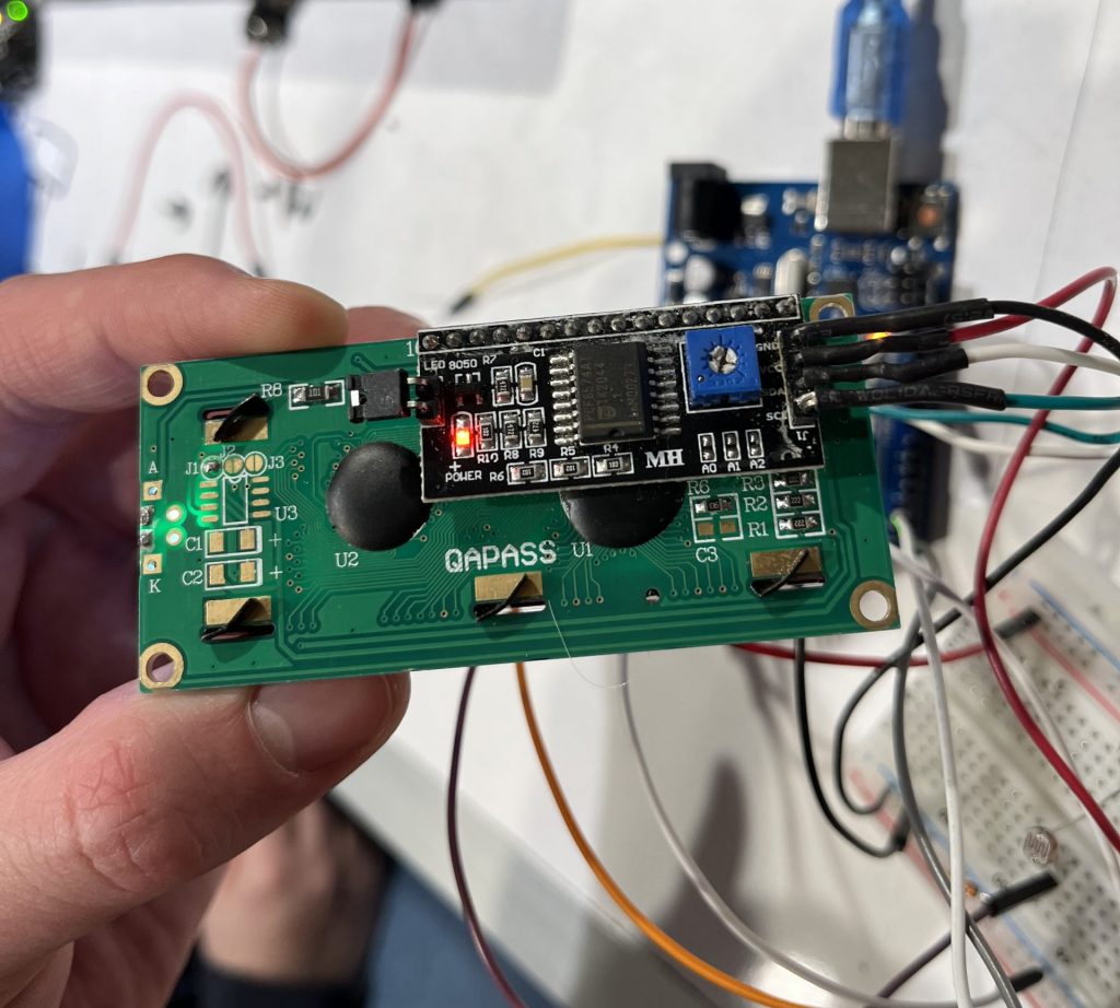
Our specialized LCD screen has a back panel that effectively simplifies the connections needed to operate it with the Arduino. However, it is critical to clarify the differences between the 4pins and double-check their connections; sometimes it is hard to notice a connection mistake when it is behind the panel.
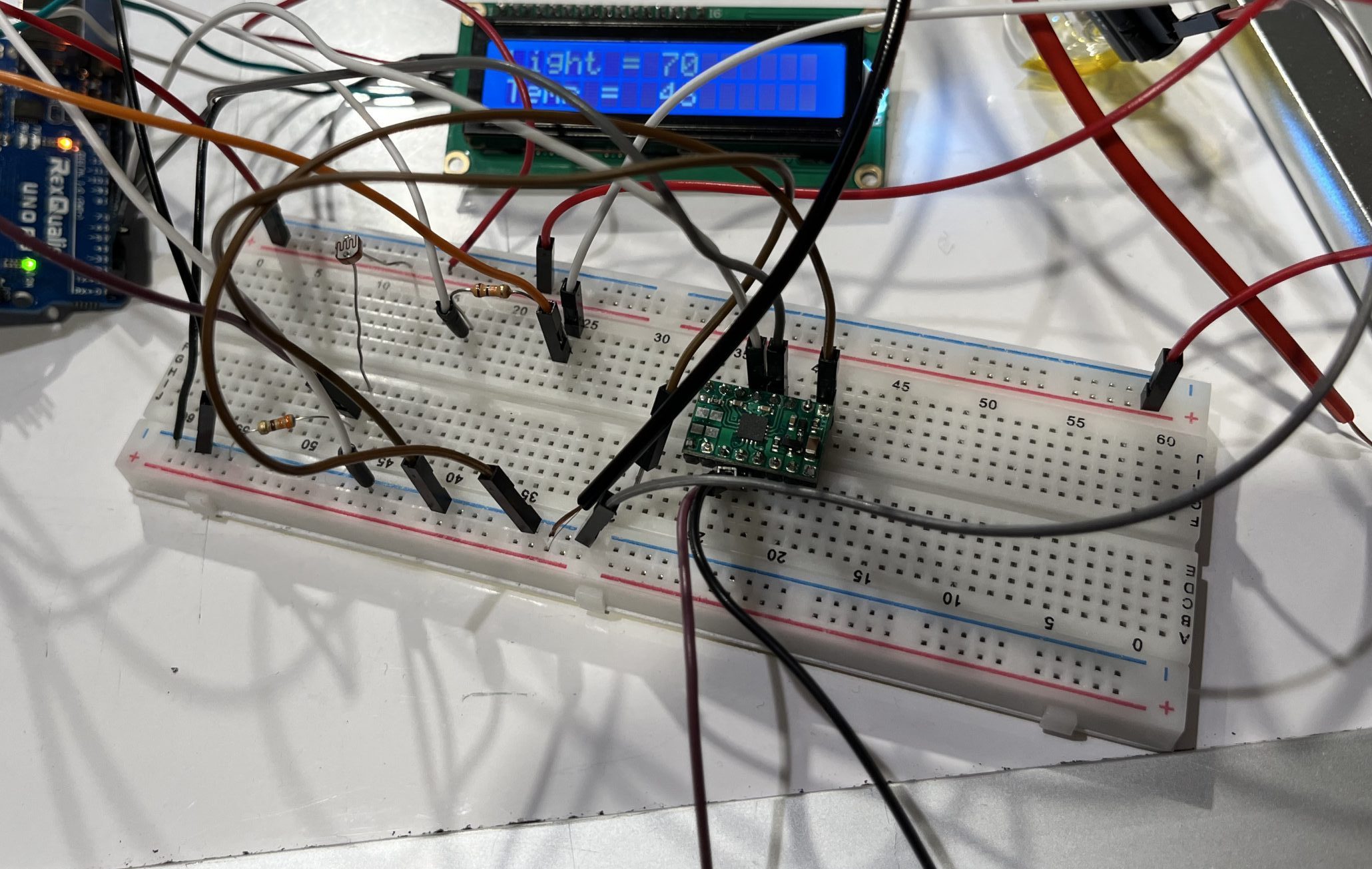
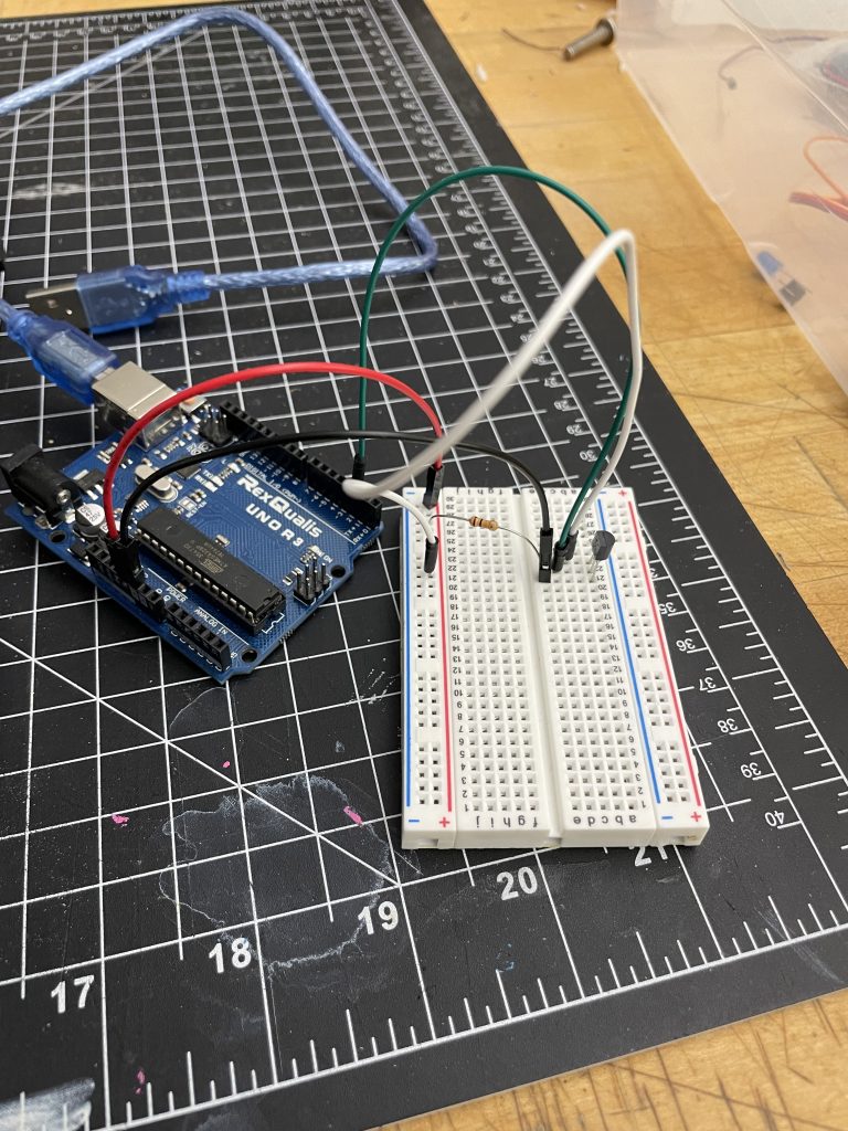
Sometimes it is helpful to have a larger-scale breadboard for managing complex cable connections. However, it needs to be noted that some of the larger breadboards are not connected across the centerline.
Discussion
-
- Highlight 1: Heating up the light bulb is relatively easy and quick, but cooling it down can be time-consuming – it would be a good idea to add an additional ventilation fan to the setup to help with it.
- Highlight 2: Photoresistor output data in combination with artificial light input is highly dependent upon the ambient light condition, the results may vary depending on the location in the studio space; therefore, it is a good idea to preset a parameter ‘ambient lighting baseline’ every time the machine starts to run for the flashlight to work with.
- Highlight 3: It was fascinating to learn the difference that H-bridge can help drive high-voltage components without a physical ‘switch’ and works with analog input, whereas the relay only works with digital inputs.
- Highlight 4: Always test run the machine on different power sources to ensure it is compatible across the board – especially need to test it with the power supply used for the presentation
- For presentation purposes, it would be great to start thinking about designing a casing for future projects – therefore the interactive feature of the machine is easier to apprehend by the audience. The idea of casing shall be evaluated from the beginning of the prototyping process for coordination of different parts within.
Functional block diagram and schematic

Code submission
//Evie and Dongtoa
  //light value to linear position
  //intor to physical computing Winter 2023


#include <LiquidCrystal_I2C_Hangul.h>
#include <Wire.h>

LiquidCrystal_I2C_Hangul lcd(0x3F, 16, 2);

int photoVal;
int temP;
int heaT;
int linearP;
int linearOUT;
int previouseOUT;

const int PHOTO = A3;
const int THERM = A2;
const int HOTB = 6;
const int MOT_0 = 10;
const int MOT_1 = 11;


void setup() {

  Serial.begin(9600);

//inputs and outputs
  pinMode(PHOTO, INPUT);
  pinMode(THERM, INPUT);
  pinMode(HOTB, OUTPUT);

  pinMode(MOT_0, OUTPUT);
  pinMode(MOT_1, OUTPUT);

// moters are off
  digitalWrite(MOT_0, HIGH);
  digitalWrite(MOT_1, HIGH);

//LCD screen setup
  lcd.begin(16, 2);
  lcd.init();
  lcd.backlight();

  lcd.setCursor(0, 0);  //goto first column (column 0) and first line (Line 0)
  lcd.print("Light ");  //Print at cursor Location
  lcd.setCursor(0, 1);  //goto first column (column 0) and second line (line 1)
  lcd.print("Temp ");   //Print at cursor location
  lcd.setCursor(10, 0);
  lcd.print("Pos");

  //source for LCD screen :https://www.instructables.com/Display-temperature-on-LCD/

}

void loop() {

  //Input values:
  photoVal = map(analogRead(PHOTO), 0, 1023, 0, 100);

  temP = map(analogRead(THERM), 0, 1023, 0, 100);

  //Out put values:
  linearOUT = (map(temP, 50, 100, 0, 3000));

  heaT = map(photoVal, 30, 100, 0, 200);

  //to show on the screen
  linearP = map(linearOUT, 0, 3000, 0, 100);

/////////////////set the screen:

  lcd.setCursor(6, 0);  //move the cursor to position 6 on row 1
  lcd.print(photoVal);
  delay(300);

  lcd.setCursor(6, 1);
  lcd.print(temP);
  delay(300);

  lcd.setCursor(14, 0);
  lcd.print(linearP);
  delay(300);


///////////////// heat bulb:

  if (photoVal > 30) {
    analogWrite(HOTB, heaT);
    // 30 is about anbient light, this way the lightbulb wont be on
    // unless there is a light next to it, giving it time to cool down
  }
  if (photoVal < 30) {
    analogWrite(HOTB, 0);
  }

//////////////////// linear actuator based on time
  //takes 3000milsecs to reach the the end. 0 is 0% heat and 3000 is 100% heat

  //if the temperature rises, the linear position increases
  if (linearOUT > previouseOUT && temP > 50) {
    digitalWrite(MOT_0, LOW);
    digitalWrite(MOT_1, HIGH);
    // how long it goes out:
    delay(linearOUT - previouseOUT);

    digitalWrite(MOT_0, HIGH);
    digitalWrite(MOT_1, HIGH);
    //how long it stops:
    delay(300);
  }

  //if the temperature decreases the linear position decreases
  if (linearOUT < previouseOUT && temP > 50) {
    digitalWrite(MOT_0, HIGH);
    digitalWrite(MOT_1, LOW);
    //how long it goes in:
    delay(previouseOUT - linearOUT);

    digitalWrite(MOT_0, HIGH);
    digitalWrite(MOT_1, HIGH);
    //how long it stops:
    delay(300);
  }

  previouseOUT = linearOUT;
  Serial.println(previouseOUT);
}