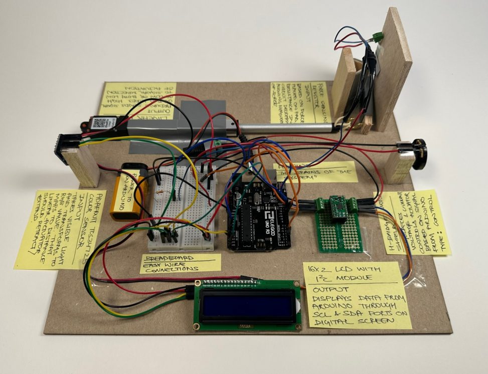
Juhi’s Double Transducer
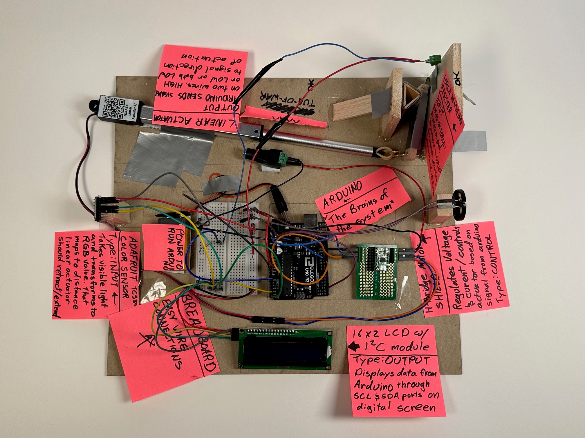
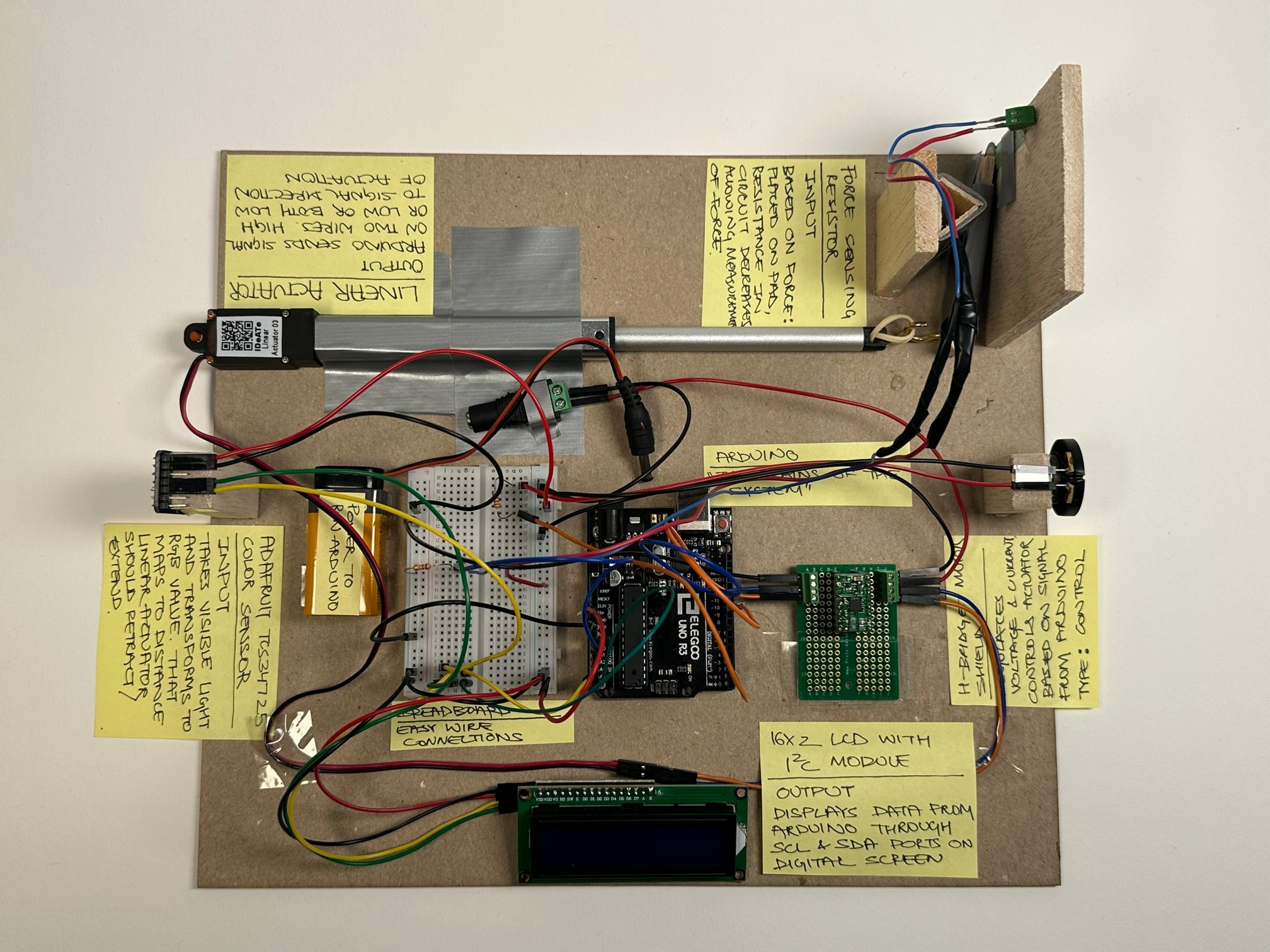
Andres’s Double Transducer
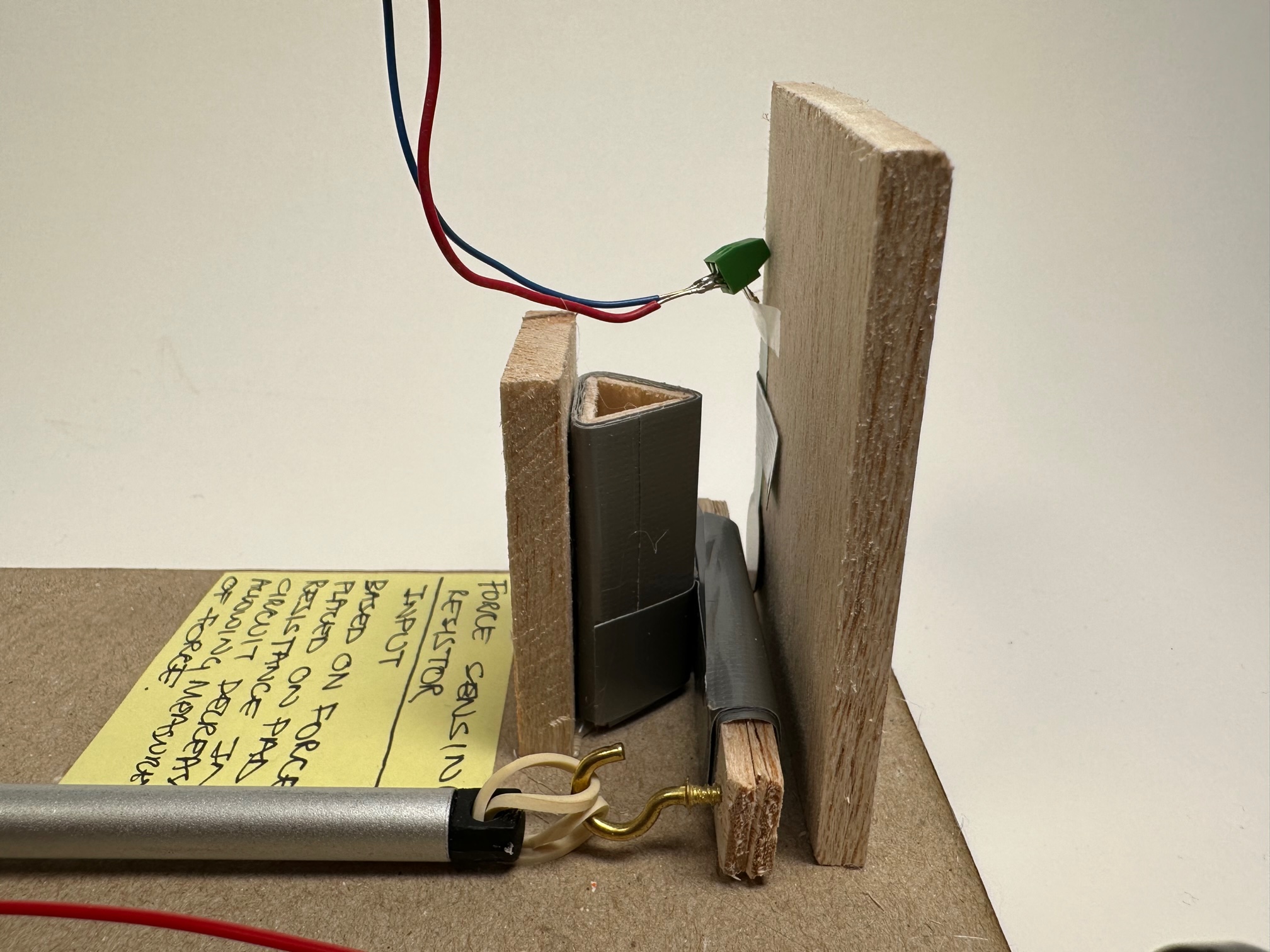
Detail Photos
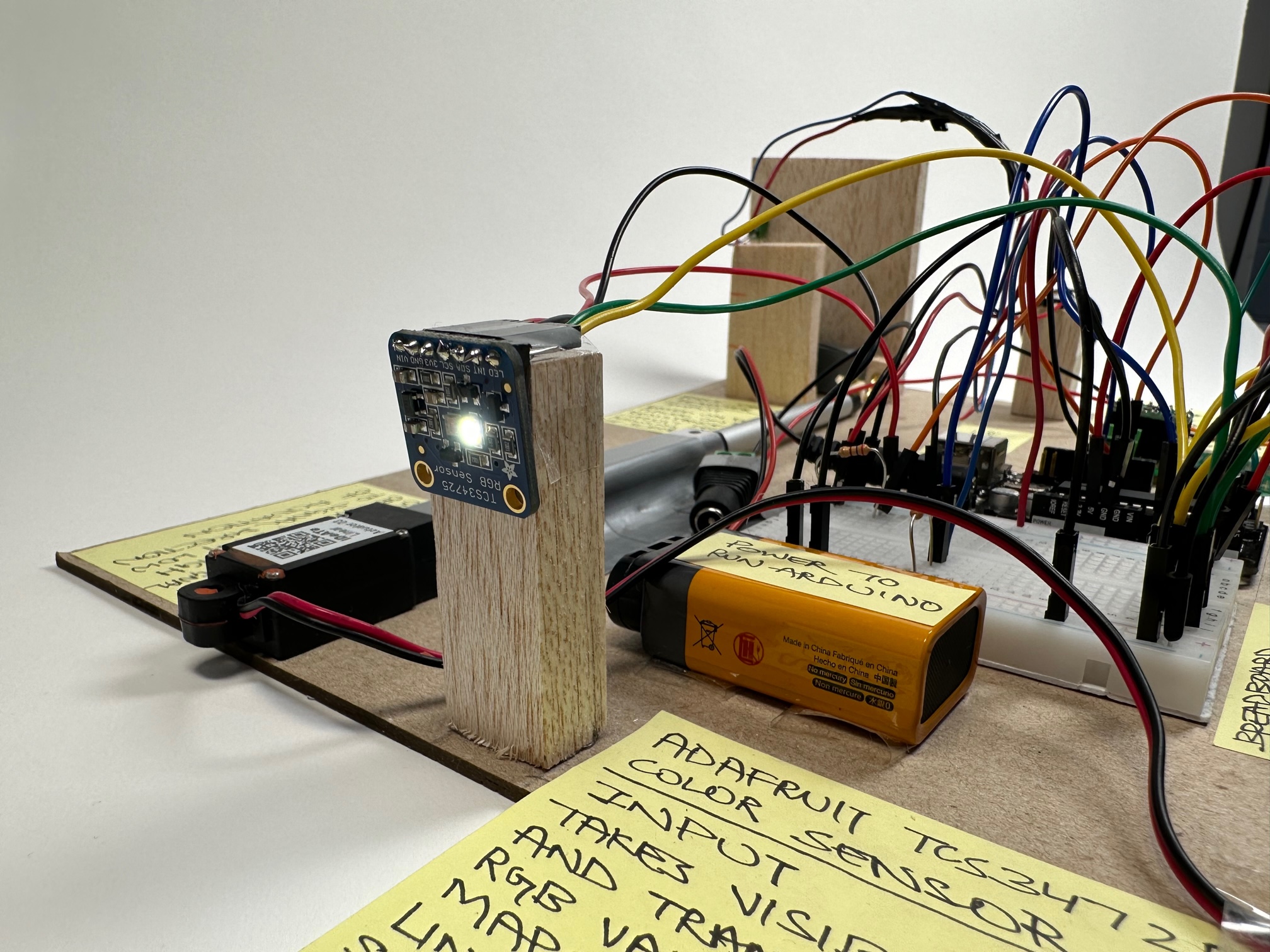
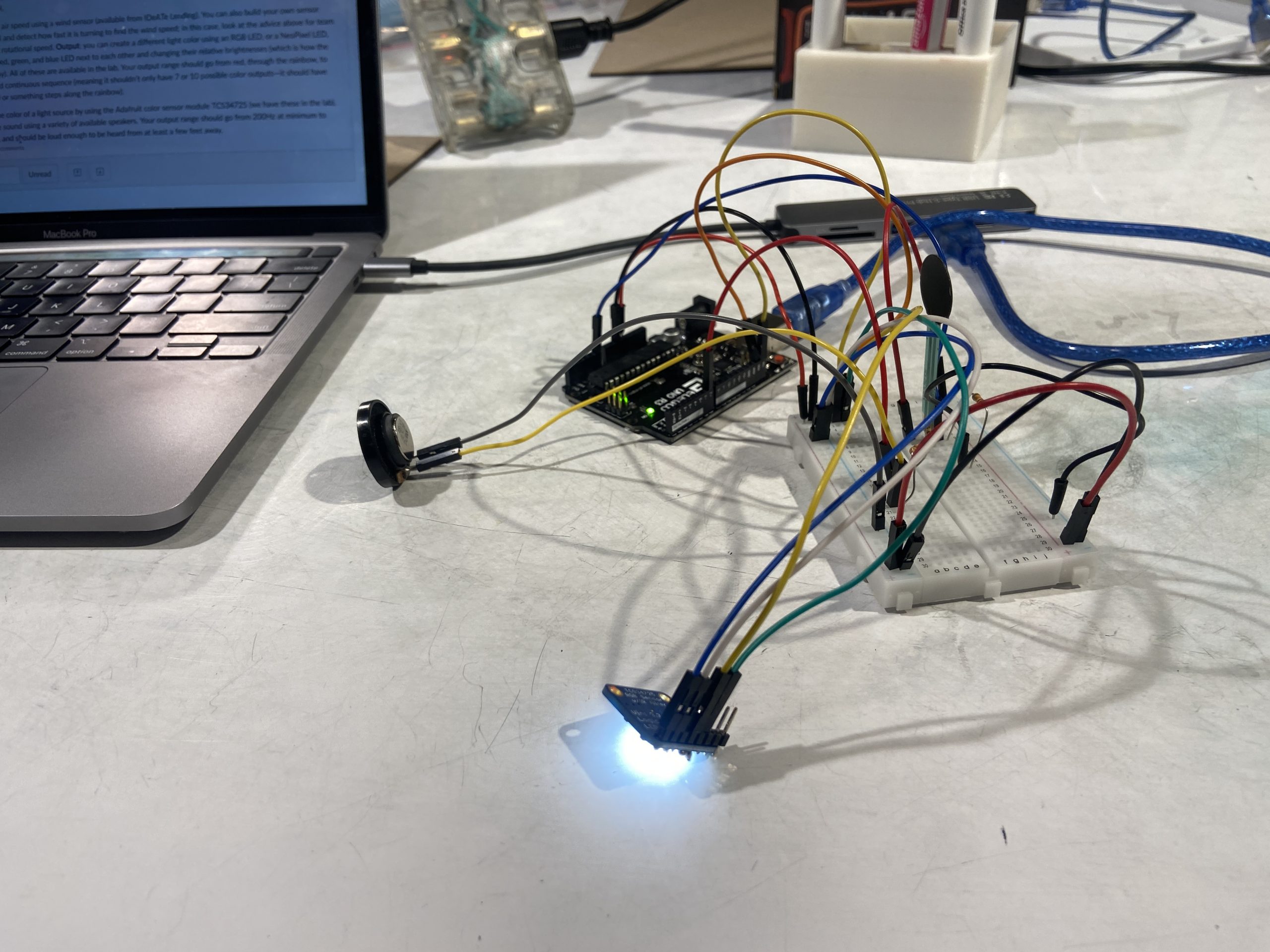
The Adafruit TCS34725 RGB color sensor is propped up by an inch to align with the output of the other team and receive the input.
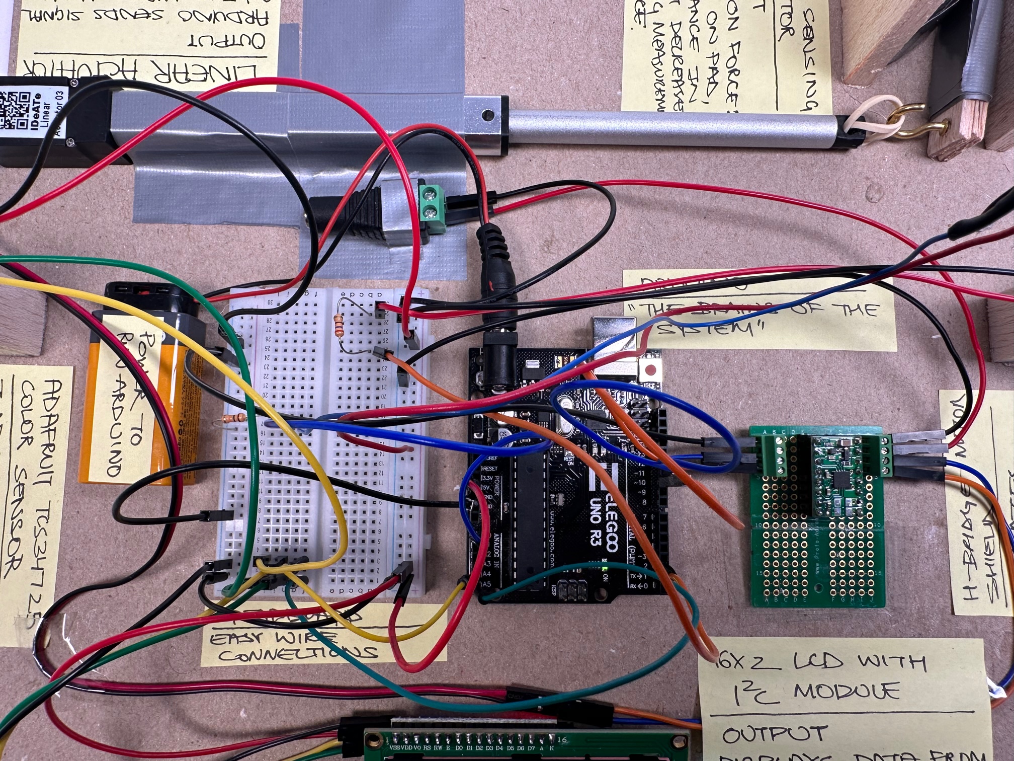
Close up of the wiring we did to connect the Arduino to different sub-systems of the double transducer project.
The linear actuator is responsible for extending and retracting the rubber band (i.e. the lever mechanism) dependent on the color read by the RGB sensor.
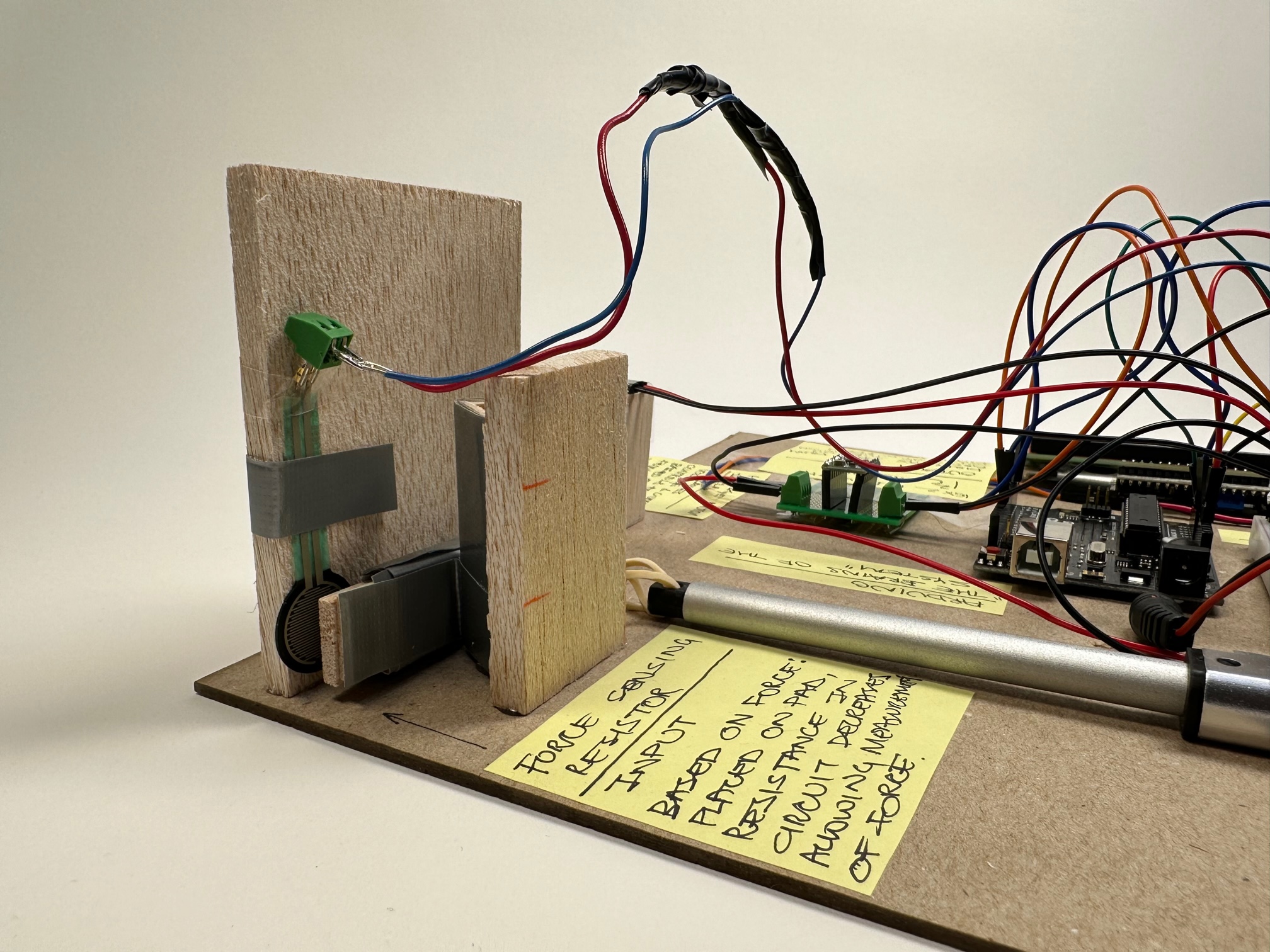
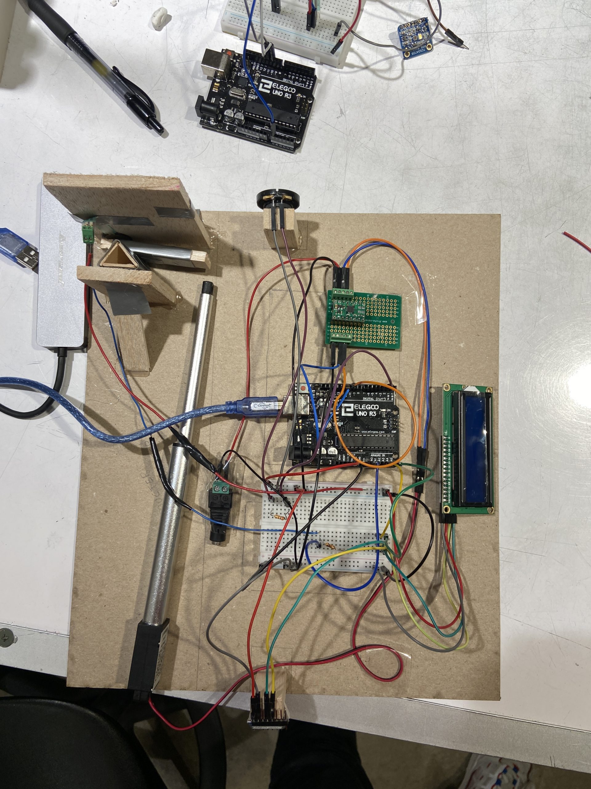
Close up of the middle step. The force sensor is supported by a wall and is being pushed by the lever pivoted on a stand, which is moved by the linear actuator.
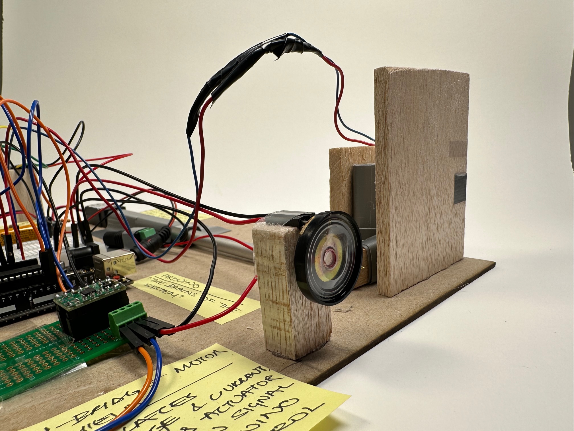
The output i.e. the speaker that varied the sound pitch (from 200Hz to 2000 Hz) according to the amount of force received by the force sensor. (In the color spectrum red being the lowest to purple being the highest)
Working Videos
Narrative Description
The machine sees the color emitted by LED, then uses the color value to expand or compress a motor which moves a lever mechanism. The force exerted by the lever mechanism is detected by a senor and is used to change the pitch of a speaker.
Progress Images
At first, we tested out all our inputs and output individually to see whether they were working or not (Juhi)
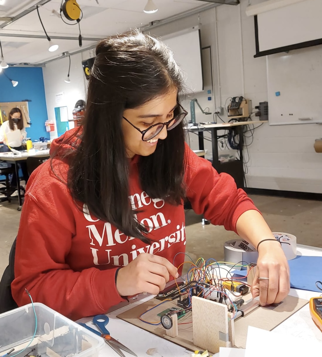
Once we had all our elements, we were experimenting with the linear actuator and its position in terms of the range we set in relation to the color spectrum (Juhi)
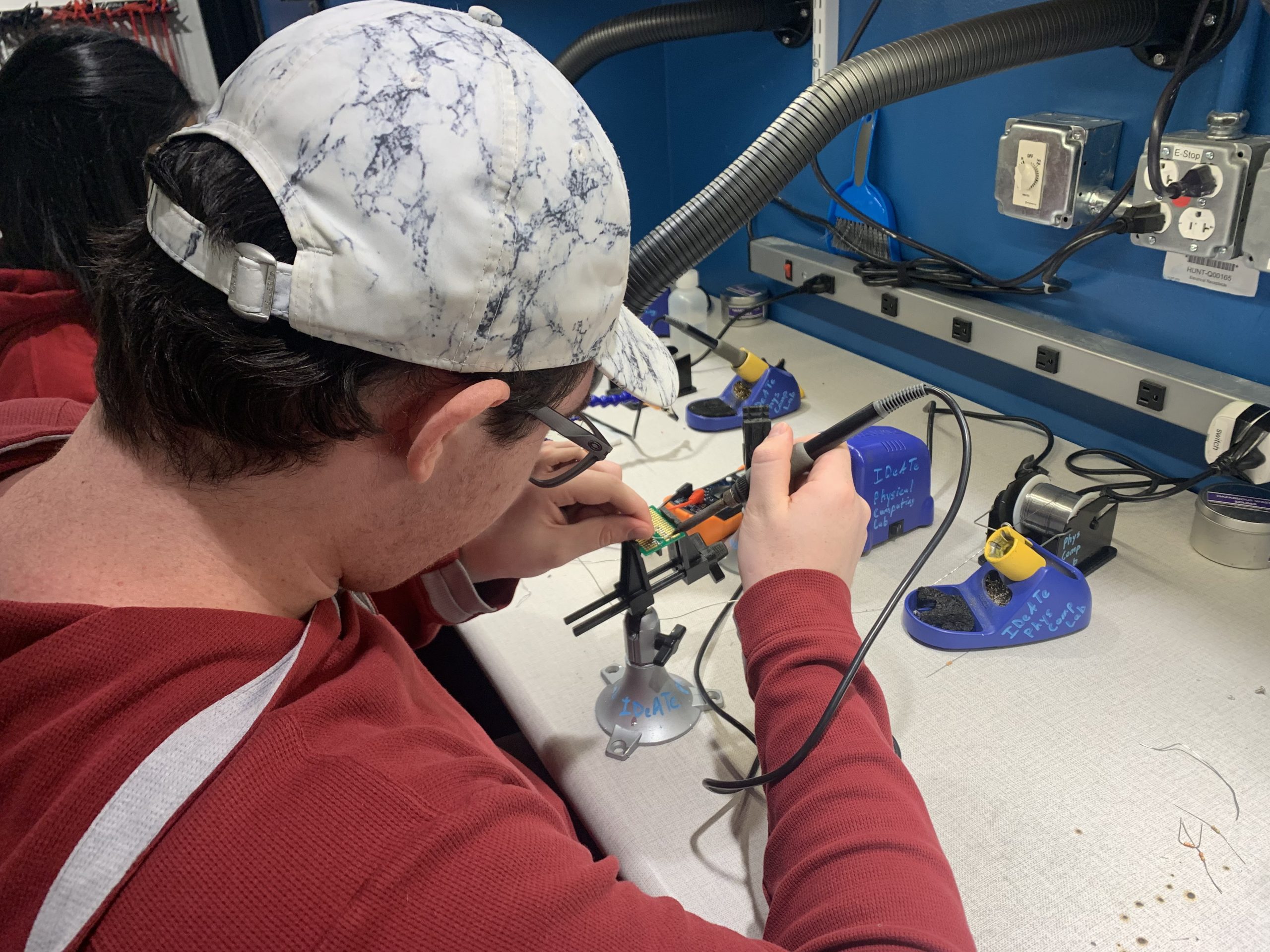
To connect our parts in relation to the other we had to solder a few things (Andres)
To create our middle step we were experimenting with different types of lever mechanisms that would suit our transducer (Andres)
Discussion
Our double transducer project, while educational, was filled with unexpected challenges. We faced many throughout the project, but the biggest were converting the RGB input signal form into a usable scale, controlling the linear actuator, and coding in general. To start with the RGB adafruit color sensor, depending on the color it ‘sees’ it outputs a RGB value to the arduino; however, we needed to convert this to a linear scale to control the linear actuator. We did this by transforming from the RGB domain to the ‘HSL’ domain where H or hue can be used to put colors on a linear scale from 0 to 360. But, not knowing anything about colors before this project, we had to do research online, speak to the professor and the TA to not only understand how to do this but understand that this was even an option. Moving on to controlling the linear actuator, as it doesn’t have an integrated control, or position controller, we had to figure out how to not only determine position but control that position using time passed and an experimentally determined rate of speed. As neither of us knew a lot about code, we had to once again conduct outside research and learn what and how to use an open loop controller which was extremely helpful in controlling both the actuator, and updates on the I2C screen. Finally, we made bug fixing our code much more challenging than it had to be. This is because we began putting things together before we had debugged each individual piece. Meaning errors propagated throughout the system that could have been fixed piecemeal if we had done more rigorous testing early on. For example, we connected the color sensor to the actuator early on and when the actuator didn’t output the correct distance, I was sure that it was because I mapped the hue incorrectly when actually it was because I was incorrectly controlling the non-feedback actuator.
Being open to change and adapting original ideas was also, in my opinion, one of the most significant and positive parts of our creation process. For instance, when we started, I was sure that a spring was the only way to go in regards to attaching the actuator to the FSR sensor, but through testing we realized a spring added unneeded complexity that just using a weak rubber band would fix. Another thing we had to be open to changing was how to transmit the force to the FSR sensor. Because it only senses compression, at first we weren’t sure of the best way to switch the tension force we were getting from the actuator to compression. We solved this issue by meeting, talking, and listing out ideas before deciding that a simple lever as seen above was the best solution. Finally on things we would have changed if there was more time, two come to mind. The first is changing from a 4 inch extending actuator to a 2 inch as the extra distance only added error to our conversion that a smaller range would have solved. The second is further research into how the Adafruit color sensor works. Because much of the code was based on examples provided by the downloaded library, we were using features and commands that we weren’t 100% certain of their purpose. Because of this, things that we could have changed or adjusted for more ease of use were taken as set in stone. For instance, the sensor has an optional white LED to make colors clearer to the sensor, but since our input was from a LED itself, for us this was unnecessary. However, we weren’t aware it could be turned off and the glare it caused, created problems we had to work around that had an extremely easy fix.
As a group some of the biggest lessons we learned from this project was to avoid unnecessary stress and take things one step at a time. I think we were worried about succeeding 100% in everything we set out to do, which is good, but not to the point of frustration. Every part had value and even if we didn’t succeed completely the learning is more important than success. The other thing we hope to take away from this into project two is while these electronics combine into one system, they are composed of many different individual components. If there is a problem it is most likely in one of these subsystems and the best practice is to start at the beginning and move up when testing.
Block and Schematic Diagram

Code
/* Double transducer: From light color to sound pitch
   {Andres Montemayor, Juhi Kedia}

   The code below processes and translates an input RGB reading
   from LED lights to a speaker pitch (200Hz to 2000Hz). The
   middle step for the double transducer is a liner actuator
   that extends and contracts according to the RGB color sensor
   reading and pushes along a force sensing resistor according to
   the color spectrum (red being the lowest and violet being the hightest).

  Pin Map:
  pin        | mode   | description

  FSR_pin    | input  | LED
  MOTORCONT1 | output | potentiometer: sets blink rate
  MOTORCONT2 | output | pushbutton: affect blink rate
  SPEAKER    | output | tone from 200 Hz to 2000 Hz based on FSR reading
  SQL      | OUTPUT/INPUT | SCREEN and ADAFRUIT go in here
  SDA      | OUTPUT/INPUT | SCREEN and ADAFRUIT go in here

  RGB sensor code sourced from adafruit Color control
  Used example code from adafuit library 'color view' and code linked below to write this:
  https://www.geeksforgeeks.org/program-change-rgb-color-model-hsv-color-model/

  Conversion from RGB to HSV values makes use of an algorithm sourced from:
  https://www.rapidtables.com/convert/color/rgb-to-hsv.html
*/


/*
   have Working: adafruit color sensor, force sensor, speaker
   in progress: done test on board
*/


#include <Wire.h>
#include "Adafruit_TCS34725.h"
#include <LiquidCrystal_I2C.h>

// set to false if using a common cathode LED
#define commonAnode true

// our RGB -> eye-recognized gamma color
byte gammatable[256];

Adafruit_TCS34725 tcs = Adafruit_TCS34725(TCS34725_INTEGRATIONTIME_50MS, TCS34725_GAIN_4X);
LiquidCrystal_I2C screen(0x27, 16, 2);

// rename pins
const int FSR_pin = A0;
const int MOTORCONT1 = 10;
const int MOTORCONT2 = 11;
const int SPEAKER = 2;

// Set variables for use throughout code
float posPast;
double travelTime;
float stopTime;
int swtch = 0;
float hPast = 0;
int swtch2 = 1;
unsigned int timer = 250;


void setup() {
  pinMode(FSR_pin, INPUT);
  pinMode(MOTORCONT1, OUTPUT);
  pinMode(MOTORCONT2, OUTPUT);
  pinMode(SPEAKER, OUTPUT);
  pinMode(A3, INPUT);
  screen.init();
  screen.backlight();
  Serial.begin(9600);

  // Begin color sensing sensor
  if (tcs.begin()) {
    Serial.println("Found sensor");
  } else {
    Serial.println("No sensor");
  }
  extend();
  delay(3000);
  stop();
}

// extends the linear actuator
void extend() {
  digitalWrite(MOTORCONT2, LOW);
  digitalWrite(MOTORCONT1, HIGH);
}
// returns the linear actuator
void retract() {
  digitalWrite(MOTORCONT2, HIGH);
  digitalWrite(MOTORCONT1, LOW);
}

//stops the linear actuator
void stop() {
  digitalWrite(MOTORCONT1, LOW);
  digitalWrite(MOTORCONT2, LOW);
}

void loop() {

  /*
  //read a pot val was used for testing
  int potVal = 0;
  //do the read and store the value into potVal
  potVal = analogRead(A3);

  //send potVal's value back to computer
  */

  //FSR control
  int fsrReading = analogRead(FSR_pin);
  //Serial.println(fsrReading);
  // this done input of fsrReading tells force on sensor 0 -> 1023... might need to adjust if too much force being put on
  // can just change spring as well

  uint16_t r, g, b, c;
  double h = 0;
  // Gather various color data from RGB sensor
  tcs.getRawData(&r, &g, &b, &c);

  // RGB to HSV
  float rNew = r / 65535.0;
  float gNew = g / 65535.0;
  float bNew = b / 65535.0;
  // RGB to HSV algorithm
  float cmax = max(rNew, max(gNew, bNew));  // maximum of r, g, b
  float cmin = min(rNew, min(gNew, bNew));  // minimum of r, g, b
  float diff = cmax - cmin;                 // diff of cmax and cmin.

  // if cmax and cmax are equal then h = 0
  if (cmax == cmin) {
    h = 0;
  }
  // if cmax equal r then compute h
  else if (cmax == rNew) {
    h = fmod(60 * ((gNew - bNew) / diff) + 360, 360);
  }
  // if cmax equal g then compute h
  else if (cmax == gNew) {
    h = fmod(60 * ((bNew - rNew) / diff) + 120, 360);
  }
  // if cmax equal b then compute h
  else if (cmax == bNew) {
    h = fmod(60 * ((rNew - gNew) / diff) + 240, 360);
  }
  Serial.print("Hue: ");
  Serial.println(h);

  //end color control h: 0 -> 360 red -> purple

  //motor control
  int travelTime = map(h, 0, 360, 0, 3000);
  int posNew = map(h, 0, 360, 0, 100);
  //int posNew = potValMap;


  if (abs(posNew - posPast) > 5) {

    if (swtch == 0) {
      float travelProportion = abs(posNew - posPast) / 100;
      stopTime = millis() + (travelTime * travelProportion);
      swtch = 1;
    }
    //Serial.println("Need to move");

    if (stopTime < millis()) {
      stop();
      posPast = posNew;
      swtch = 0;
    }
    if (posNew < posPast) {
      retract();
      Serial.println("retract");
    }
    if (posNew > posPast) {
      extend();
      Serial.println("extend");
    }
  }

  /*
  Serial.print("PosNew: ");
  Serial.println(posNew);
  Serial.print("posPast: ");
  Serial.println(posPast);
  */

  //speaker control
  int pitch = map(fsrReading, 0, 1023, 200, 2000);  //dropped from 1023 to 900 because sensor wasn't reaching max
  //Serial.println("pitch: ");
  //Serial.println(pitch);
  tone(SPEAKER, pitch, 0);  //(pin, frequency, delay between tones: should be 0)


  //lcd screen
  //only want to update every quarter of a second so made swtch2 to do that
  if (swtch2 == 1) {
    Serial.println("screen update");
    screen.clear();
    screen.home();
    screen.print("i:");
    int hPrint = map(h, 0, 360, 0, 99);
    screen.print(hPrint);
    screen.setCursor(6, 0);
    screen.print("m:");
    screen.print(posNew);
    screen.setCursor(8, 1);
    int fsrPrint = map(fsrReading, 0, 1023, 0, 99);
    screen.print(fsrPrint);
    screen.setCursor(12, 1);
    screen.print("o:");
    int pitchPrint = map(pitch, 200, 2000, 0, 99);
    screen.print(pitchPrint);
    swtch2 = 0;
  }

  if (millis() >= timer) {
    swtch2 = 1;
    timer += 200;
  }
}