Angie Wang, Stanley Ip, Michelle Liu
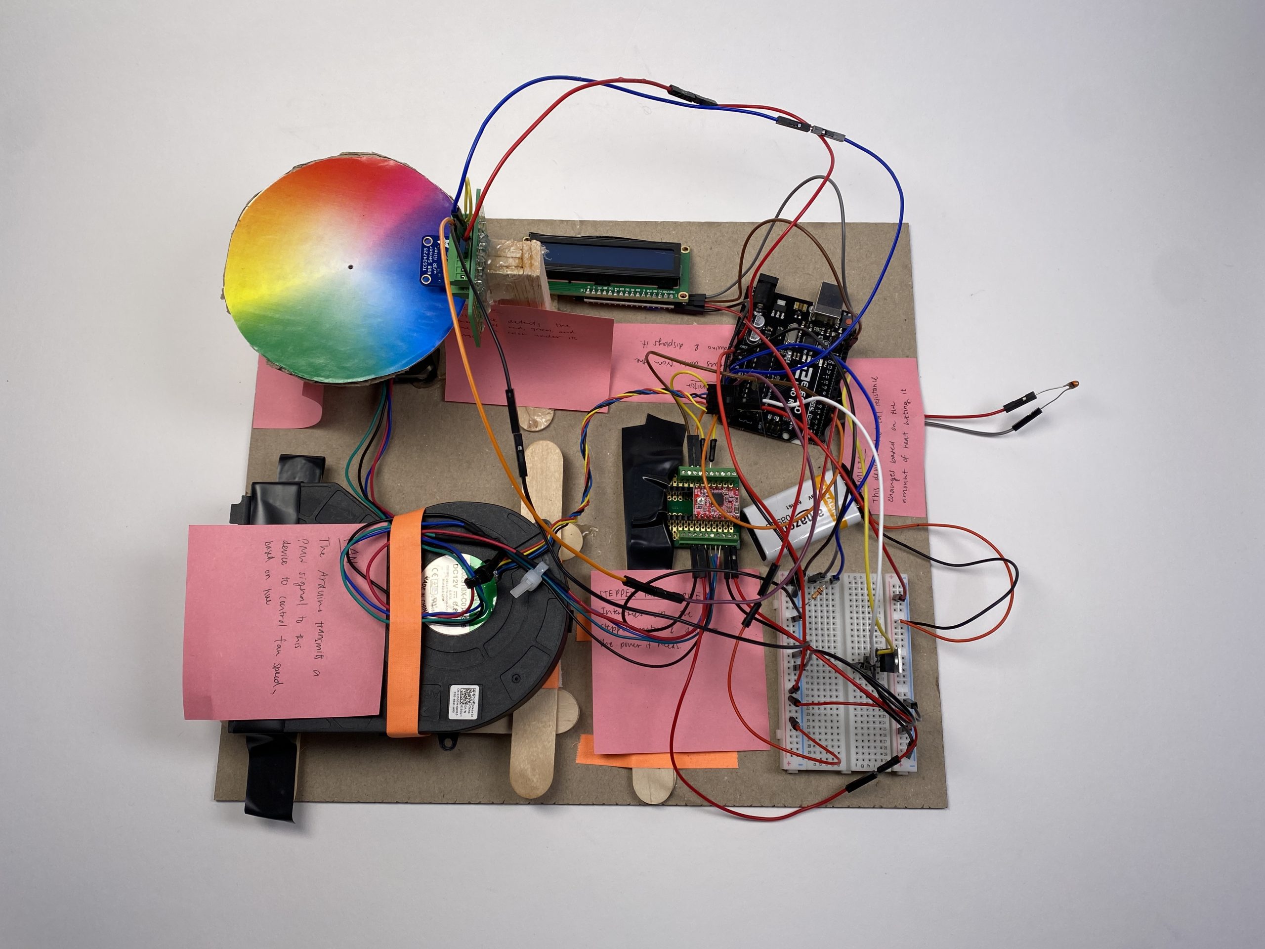
Top view of Stanley’s Double Transducer. Thermistor (left), fan (right)
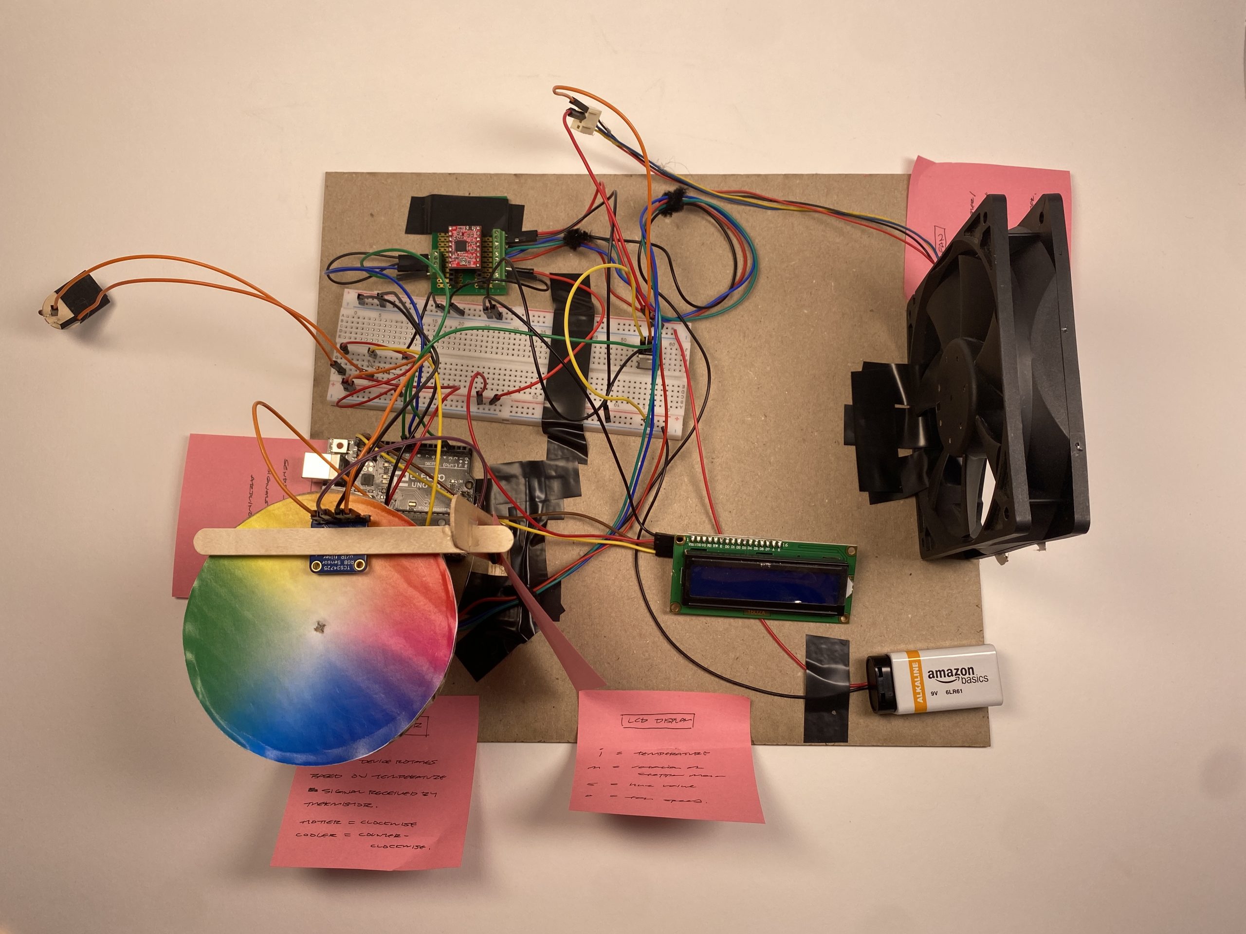
Top view of Michelle’s Double Transducer. Fan (left), thermistor (right).
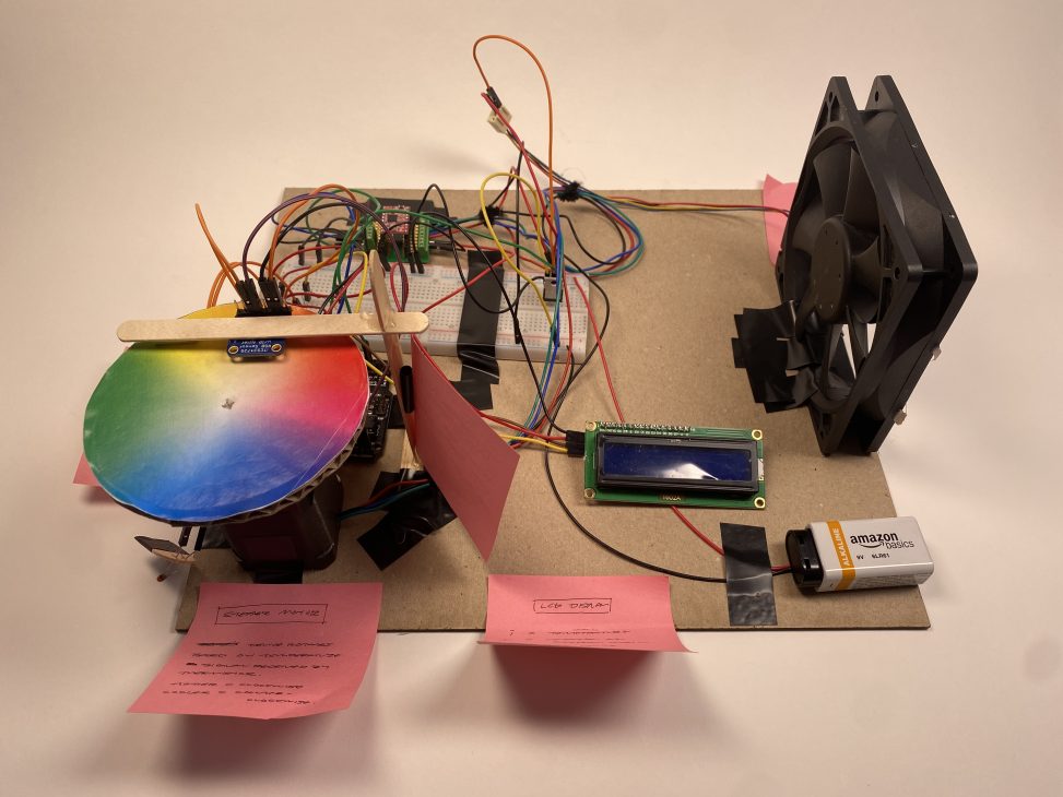
Top view of Angie’s Double Transducer. Thermistor(Middle-left, labeled as “INPUT”), Fan(Top-right, labeled as “OUTPUT”)
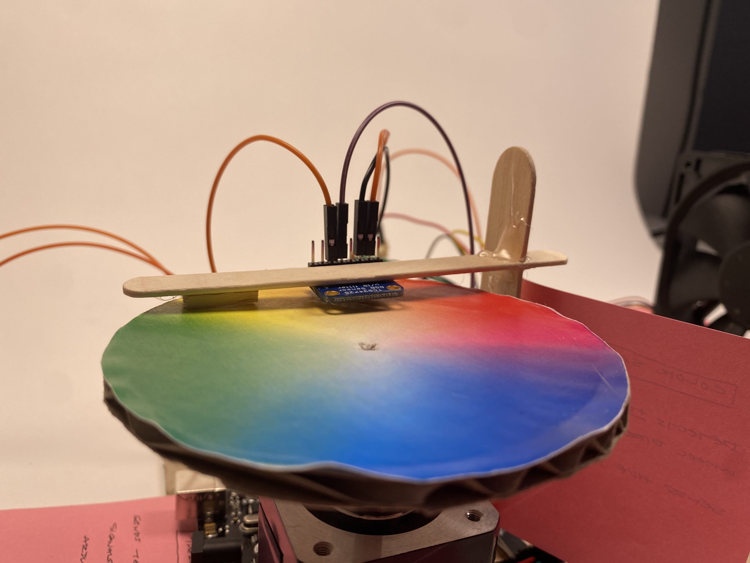
Adafruit color sensor secured directly above color wheel, which is spun by a stepper motor.
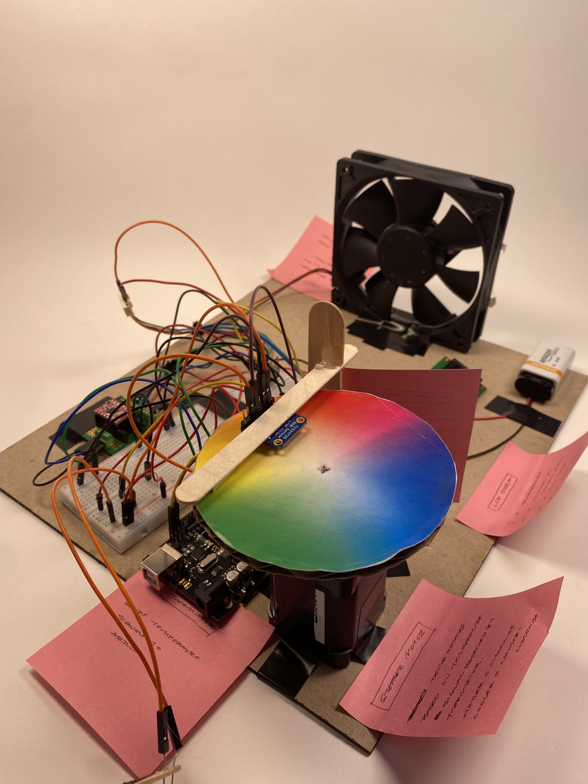
Another angle of the Adafruit color sensor secured above the color wheel and overview of some of the wiring we did to connect the steps.
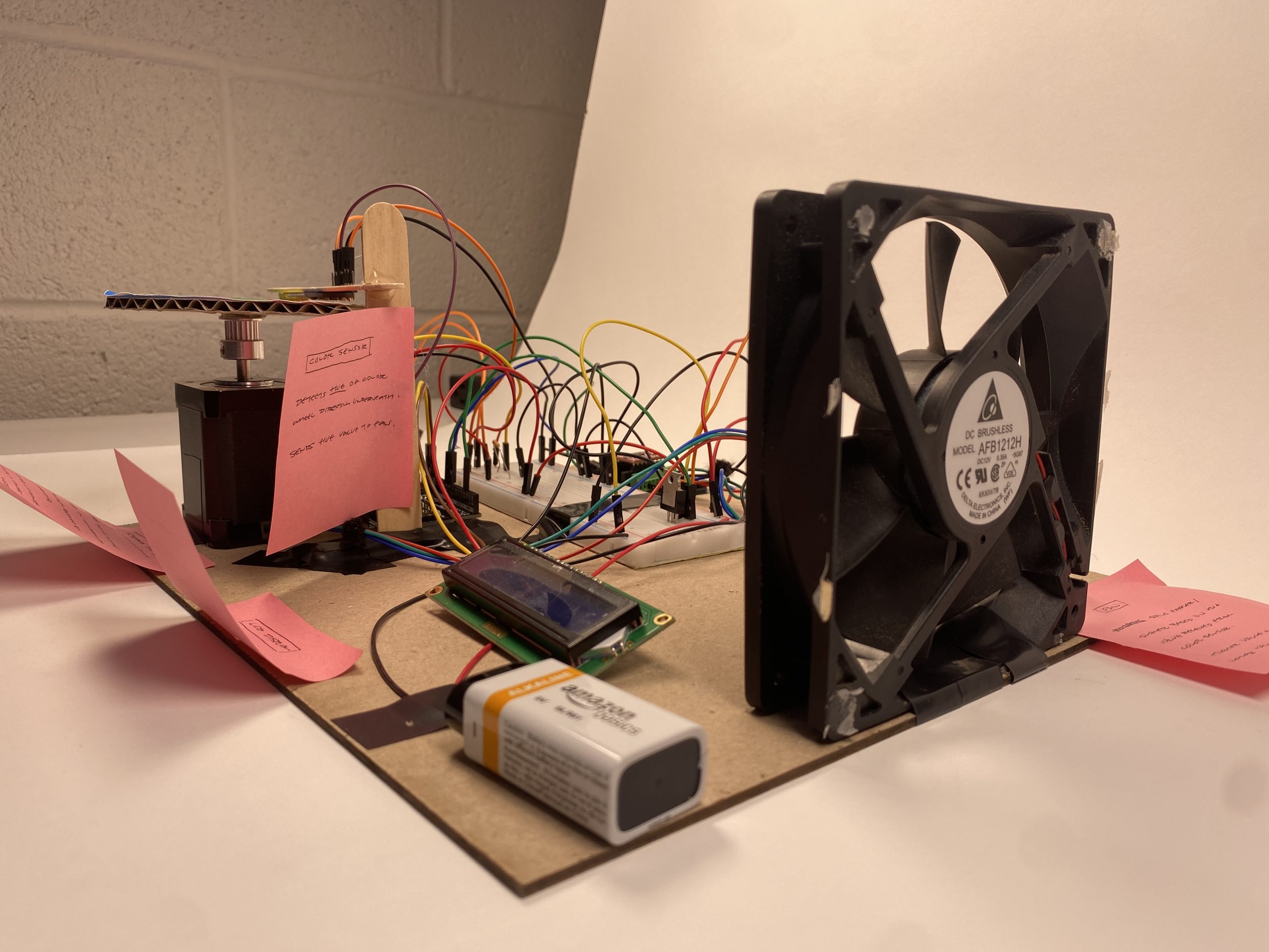
Close up of the fan and LED setup.
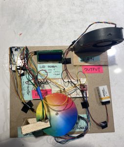
Final Working Model:
Stanley
Michelle
Narrative Description:
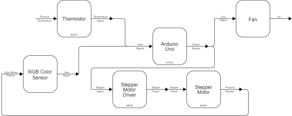
The thermistor picks up on the temperature being emitted, and based on how high or low the temperature is, the Arduino Uno will determine how much to rotate a stepper motor. A color wheel is attached to the stepper motor, and an RGB sensor will detect the hue rotated in front of it. This hue then determines the wind speed.
Process:
Testing the Adafruit sensor and stepper motor to make sure these middle step components work reliably. – Stanley
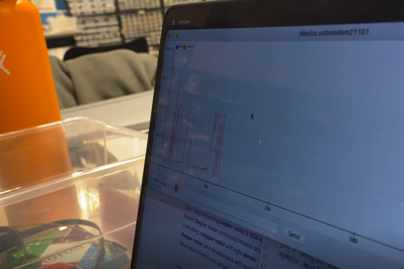
Getting the color sensor to pick up hue from the color wheel. As the color wheel spins, the hue value is recorded and is represented by the graph on screen. – Stanley
Getting the fan to respond to hue. A higher hue value (blues, purples) corresponds to higher fan speed, and lower hue values (red) corresponds to lower fan speed. – Michelle
Putting it all together (stepper motor, color wheel, fan) – Michelle
Discussion:
From the beginning of the project, we didn’t expect that our direction of going from a temperature input, to color, and fan speed would be technically challenging to execute. In particular, there were a few external things we had to learn, from learning how to use a MOSFET to control fan speed, to using a driver for the stepper motor, etc. We worked through this by taking the time to understand each component individually first – their capabilities, how the hardware itself works, how to speak to it through code, etc. and that helped us get a holistic idea of how we can get each component to communicate with each other.
Needless to say, there was a lot of debugging in our process. With so many new components and systems, it was difficult to pinpoint exactly which part was going wrong – whether it was the software, weak connections, or just a single wire plugged incorrectly. Oftentimes, we would mess with the code and wiring a lot just to find that the breadboard was faulty. Towards the end, we learned to use software workarounds for hardware problems. For example, with the RGB sensor, it was difficult to figure out a way to physically set the stepper motor such that the low temperature corresponds to the red part (low hue value) of the color wheel. Instead, we wrote a function to rotate and calibrate the color wheel, so that a lower temperature always corresponds to red, and a higher temperature always corresponds to purple.
In the end, we are glad that we followed through with the idea, using these different dimensions (temperature, hue, fan speed) in a novel yet cohesive way, and it was definitely a very productive experience in learning how to work with hardware and software simultaneously and creatively.
Block Diagram & Schematic:
![]()
Code:
/*
* TEMPERATURE > COLOR > FAN SPEED DOUBLE TRANSDUCER
* Michelle Liu, Stanley Ip, Angie Wang
*
* The thermistor picks up on the temperature being emitted, and based on how high or
* low the temperature is, the Arduino Uno will determine how much to rotate a stepper motor.
* A color wheel is attached to the stepper motor, and an RGB sensor will detect the hue
* rotated in front of it. This hue then determines the fan speed.
*
* Pin Map:
variable name | mode | pin | description
-----------------------------------------------
FAN_PIN | output | 10 | controls fan speed
STEP_PIN | output | 2 | stepper motor: sets stepper position
DIR_PIN | output | 3 | stepper motor: sets stepper direction
THERMO_PIN | output | A0 | thermistor: reads in resistance from the thermistor
*
* Credits:
* RGB sensor code referenced from the Adafruit TCS34725 breakout library example
* code: https://learn.adafruit.com/adafruit-color-sensors/arduino-code
*
* Algorithm for converting RGB values to hue values referenced from
* https://www.geeksforgeeks.org/program-change-rgb-color-model-hsv-color-model/
*
* Stepper motor code referenced from the course website:
* https://courses.ideate.cmu.edu/60-223/s2023/tutorials/stepper
*
* LCD display code referenced from the course website:
* https://courses.ideate.cmu.edu/60-223/s2023/tutorials/I2C-lcd
*/


#include <Wire.h>
#include "Adafruit_TCS34725.h" // ADAFruit TCS34725 driver for ADAFruit TCS34725 RGB Color Sensor by Adafruit
#include <AccelStepper.h> // AccelStepper stepper motor driver by Mike McCauley
#include <LiquidCrystal_I2C.h> // LiquidCrystal I2C LCD display driver by Frank de Brabander

LiquidCrystal_I2C screen(0x27, 16, 2);

Adafruit_TCS34725 tcs = Adafruit_TCS34725(TCS34725_INTEGRATIONTIME_614MS, TCS34725_GAIN_1X);

// WIRING
const int FAN_PIN = 3;
const int STEP_PIN = 8;
const int DIR_PIN = 9;
const int THERMO_PIN = A0;
const int FAN_START_SPEED = 0;

AccelStepper myMotor(1, STEP_PIN, DIR_PIN);

int pos = 800; // variable to store motor position instruction
int fanSpeed = 0;
int dispDelay = 0;

void setup(void) {
  screen.init();
  Serial.begin(9600);

// LCD DISPLAY SETUP

  screen.backlight();
  screen.home();

// RGB SENSOR SETUP

  if (tcs.begin()) {
    Serial.println("Found sensor");
  } else {
    Serial.println("No TCS34725 found ... check your connections");
    while (1);
  }

// STEPPER MOTOR SETUP

  myMotor.setMaxSpeed(1000); // measured in steps per second
  myMotor.setAcceleration(500); // measured in steps per second squared

  initializeMotorPos();

  pinMode(FAN_PIN, OUTPUT);
  pinMode(THERMO_PIN, INPUT);
  analogWrite(FAN_PIN, FAN_START_SPEED);

}

// HUE ALGORITHM
// Algorithm from https://www.geeksforgeeks.org/program-change-rgb-color-model-hsv-color-model/
// Range: 0 (red) - 360 (violet)
double calculateHue(uint16_t r, uint16_t g, uint16_t b) {
  double rDepth = r / 65535.0;
  double gDepth = g / 65535.0;
  double bDepth = b / 65535.0;

  double rgbMax = max(max(gDepth, bDepth), rDepth); // maximum of r, g, b
  double rgbMin = min(min(gDepth, bDepth), rDepth); // minimum of r, g, b

  double rgbDiff = rgbMax - rgbMin; // diff of cmax and cmin.

  if (rgbDiff == 0) {
    return 0.0;
  } else if (rgbMax == rDepth) {
    return fmod(60.0 * ((gDepth - bDepth) / rgbDiff) + 360.0, 360);
  }
  else if (rgbMax == gDepth) {
    return fmod(60 * ((bDepth - rDepth) / rgbDiff) + 120, 360);
  } else {
    return fmod(60 * ((rDepth - gDepth) / rgbDiff) + 240, 360);
  }
}

// Reads RGB sensor data without introducing a delay like the built-in function does
void getRawData_noDelay(uint16_t *r, uint16_t *g, uint16_t *b, uint16_t *c)
{
  *c = tcs.read16(TCS34725_CDATAL);
  *r = tcs.read16(TCS34725_RDATAL);
  *g = tcs.read16(TCS34725_GDATAL);
  *b = tcs.read16(TCS34725_BDATAL);
}

// initialize motor pos to approximately red
void initializeMotorPos() {
  uint16_t r, g, b, c, colorTemp, lux;

  getRawData_noDelay(&r, &g, &b, &c);
  int hue = (int)calculateHue(r, g, b);

// rotate the stepper motor by 1 degree until the hue reaches a value close to red
  while (hue > 15) {
    getRawData_noDelay(&r, &g, &b, &c);
    hue = (int)calculateHue(r, g, b);
    myMotor.move(1);
    myMotor.run();
  }
  Serial.print("RED FOUND: ");
  Serial.println(myMotor.currentPosition());
  myMotor.setCurrentPosition(0);
}

// debugging helper function for printing values with their labels
void p(String label, int val) {
  Serial.print(label + ": "); Serial.print(val, DEC); Serial.print(" ");
  Serial.println(" ");
}

void displayVal(String c, int i) {
  screen.print(c);
  screen.print(":");
  screen.print(i < 10 ? "0" : "");
  screen.print(i < 10 ? "0" : "");
  screen.print(i);
}

/*
   i = input, iMax = input upper range
   m = middle-step actuator value, mMax = middle-step actuator value upper range
   s = middle-step sensor value, mMax = middle-step sensor value upper range
   o = output, oMax = middle-step actuator value upper range
*/
// helper function for displaying values on the LCD screen
void displayLCD(int i, int iMax, int m, int mMax, int s, int sMax, int o, int oMax) {
  int iNorm = map(i, 0, iMax, 0, 99);
  int mNorm = map(m, 0, mMax, 0, 99);
  int sNorm = map(s, 0, sMax, 0, 99);
  int oNorm = map(o, 0, oMax, 0, 99);

  displayVal("i", iNorm);
  screen.print("  ");

  displayVal("  m", mNorm);

  screen.setCursor(1, 6);

  displayVal("s", sNorm);
  screen.print("  ");

  displayVal("  o", oNorm);

   screen.print("      ");

  if (dispDelay > 100) {
    dispDelay = 0;
    screen.clear();
  }
}

void loop() {
  int thermoVal = analogRead(THERMO_PIN);

  pos = map(thermoVal, 450, 600, 0, 200);

  myMotor.moveTo(-pos); // and tell the motor to go there
  myMotor.run(); // call this function as often as possible

  uint16_t r, g, b, c, colorTemp, lux;

  getRawData_noDelay(&r, &g, &b, &c);
  int hue = (int)calculateHue(r, g, b);

  fanSpeed = map(hue, 0, 360, FAN_START_SPEED, 255);

  analogWrite(FAN_PIN, fanSpeed);

  displayLCD(thermoVal, 1023, pos, 400, hue, 360, fanSpeed, 255);

  dispDelay += 1;
}