Team members:
Lily Hummel & Caleb Sun
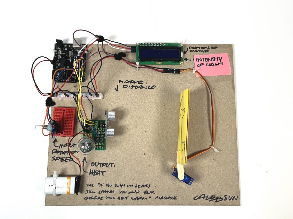
Caleb’s Double Transducer
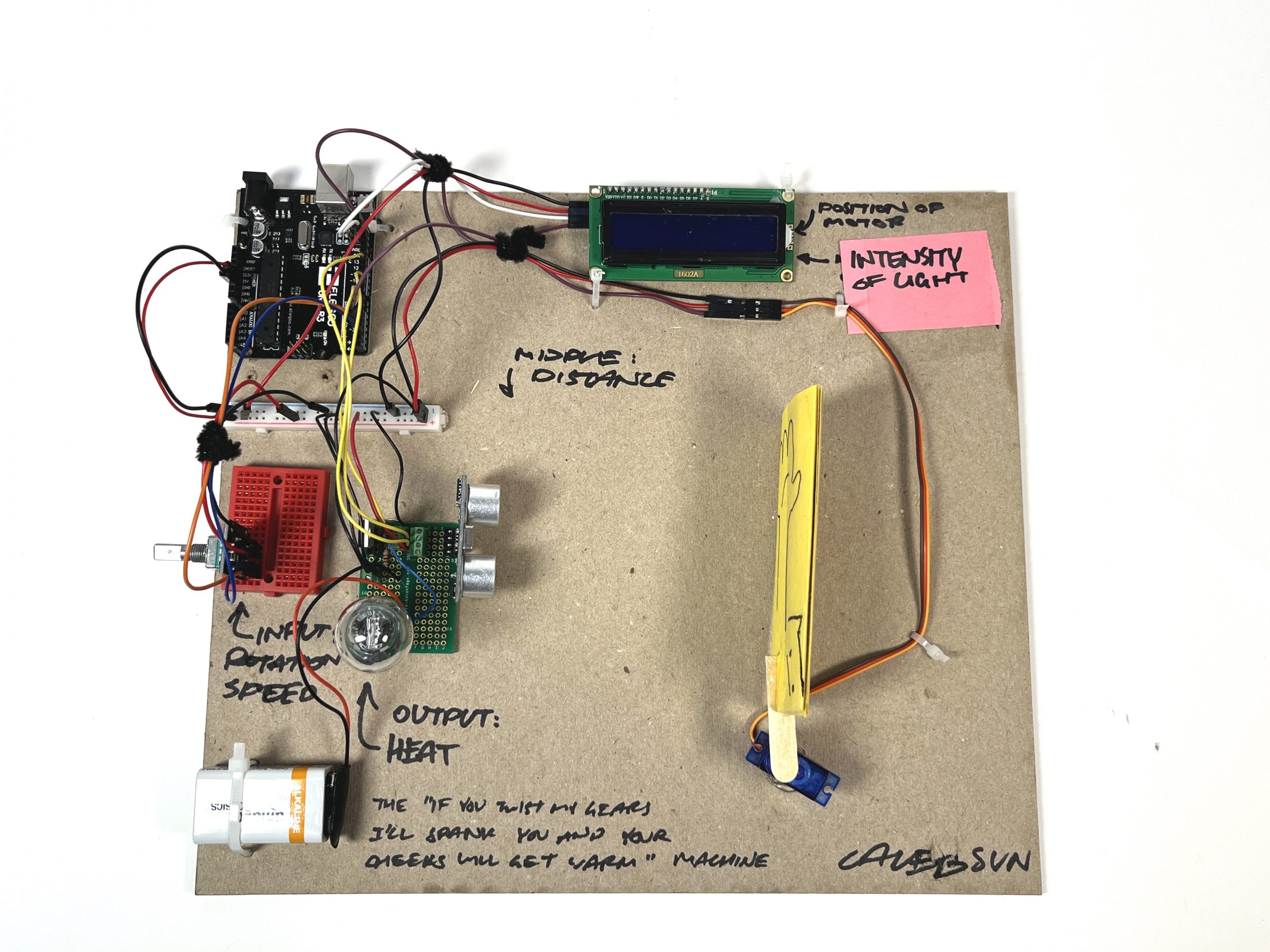
Caleb’s Double Transducer
Detail Pictures
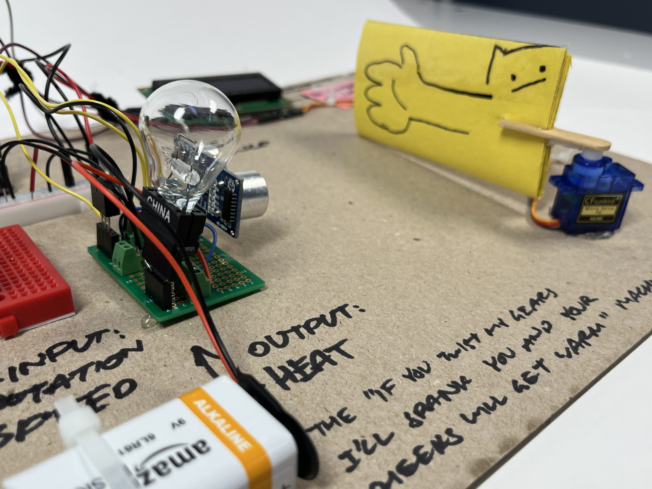
Closeup of the arm attached to Caleb’s servo motor.
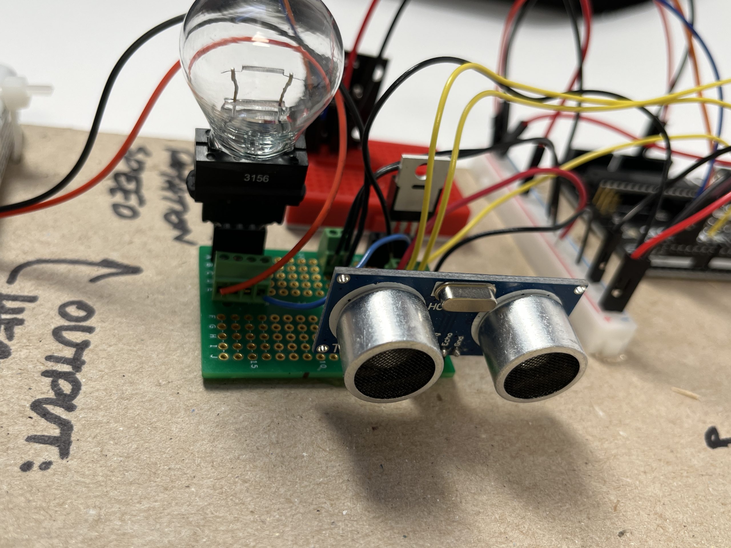
Closeup of Caleb’s soldering for the middle and end stage of the transducer.
Process Pictures
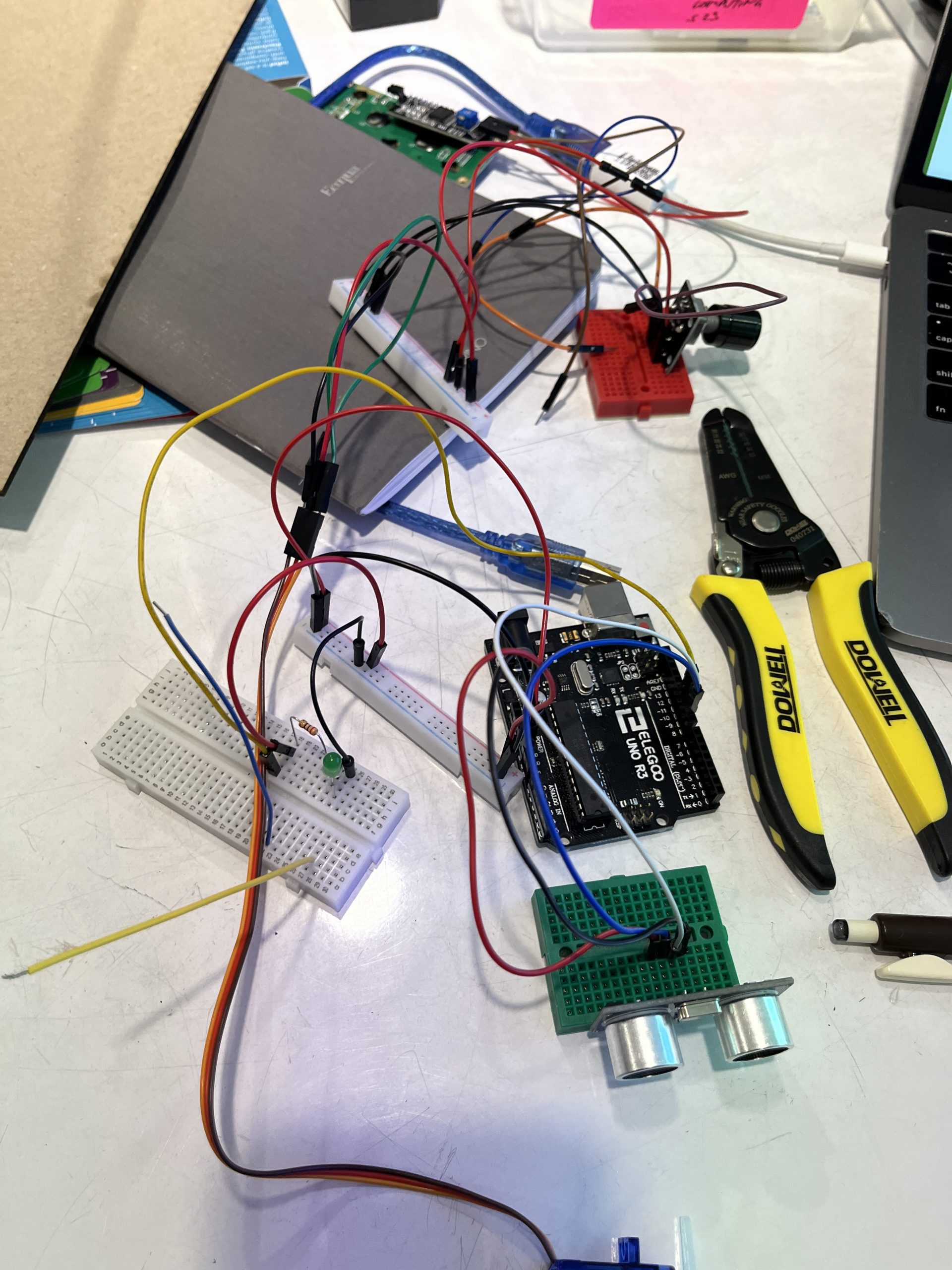
Caleb’s Process 1: Early stage process where the pieces are still in stages.
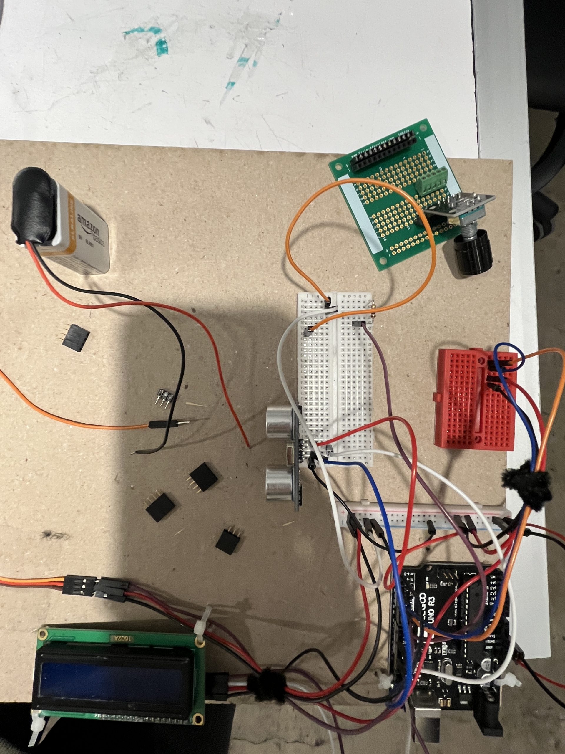
Caleb’s Process 2: Image taken shortly after deciding to solder a portion of the transducer together, causing mass destruction to the original transducer.
Lily’s Double Transducer
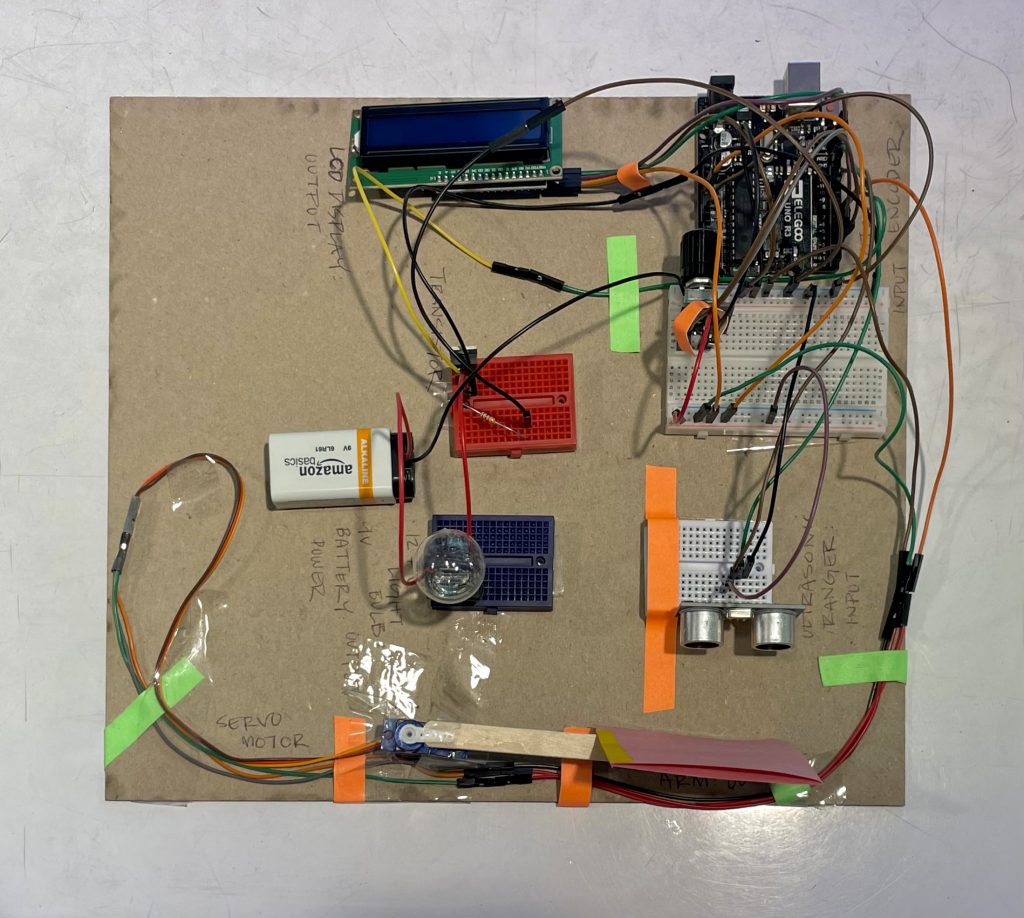
This is the overall setup of the double transducer.
Detail Pictures
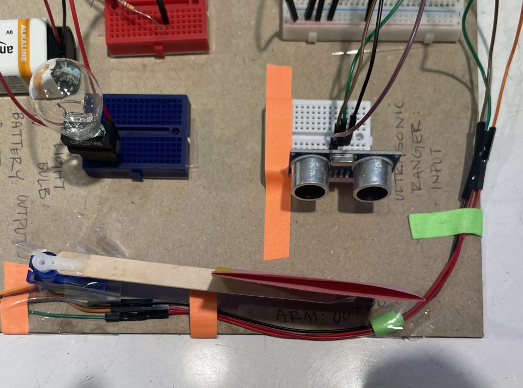
The arm of the servo motor is long enough to allow a bigger difference in arm position changes. This allows the ultrasonic ranger to record a bigger difference in distance.
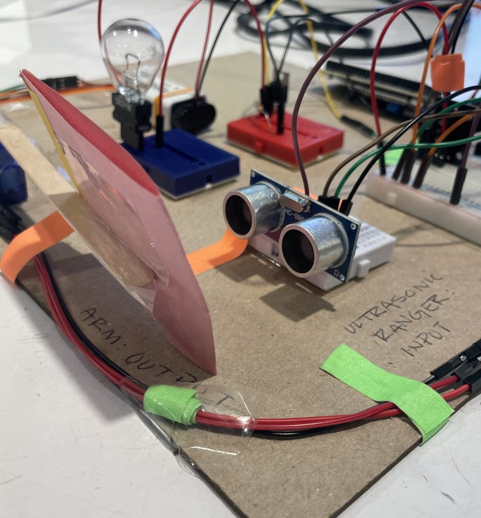
The arm of the servo motor is long enough to allow a bigger difference in arm position changes. This allows the ultrasonic ranger to record a bigger difference in distance.
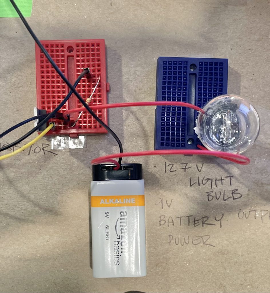
The 9V battery and lightbulb are connected to a transistor that allows the arduino to communicate with the lightbulb while also supplying enough power to power the lightbulb.
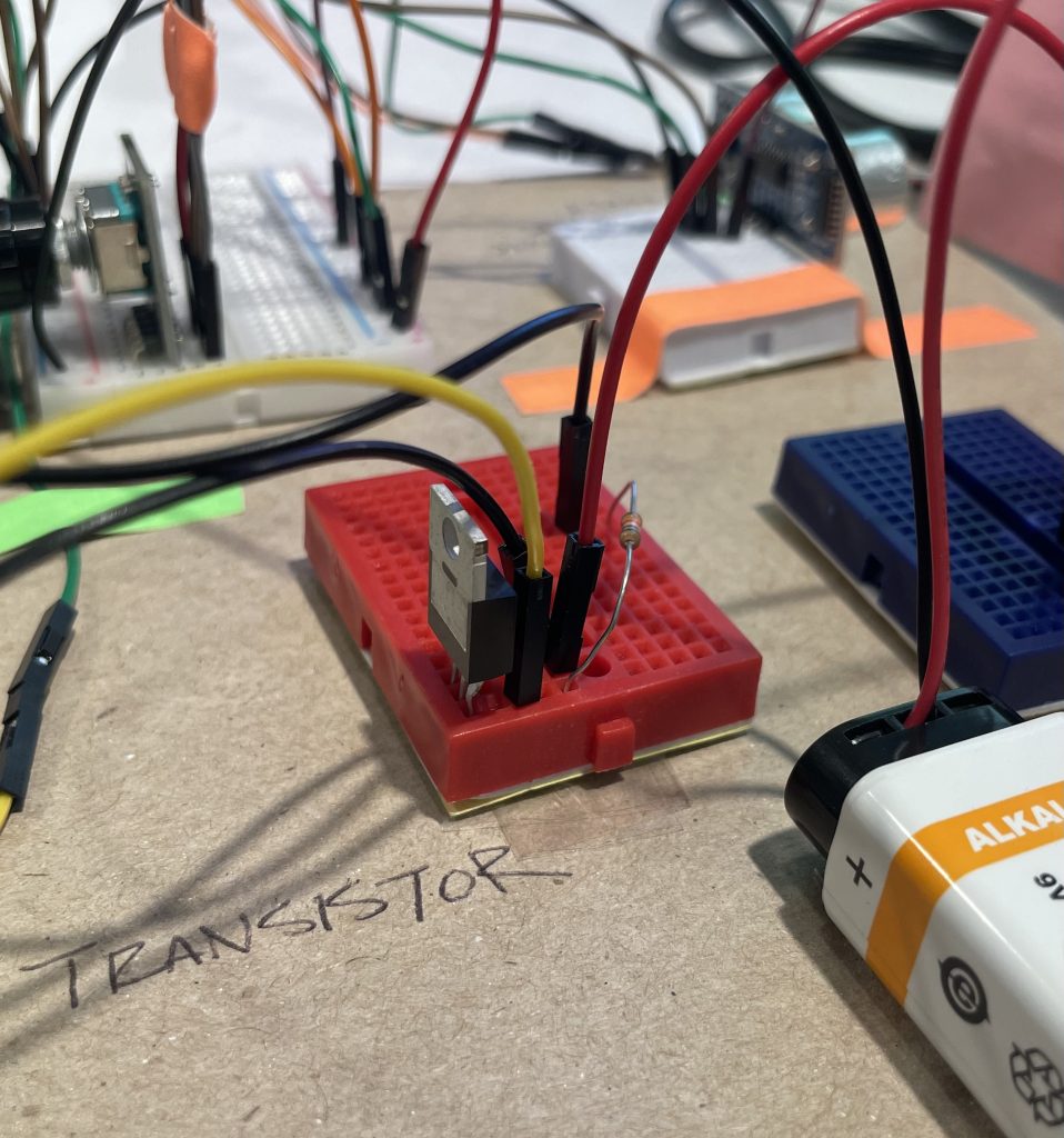
The 9V battery and lightbulb are connected to a transistor that allows the arduino to communicate with the lightbulb while also supplying enough power to power the lightbulb.
Process Photos
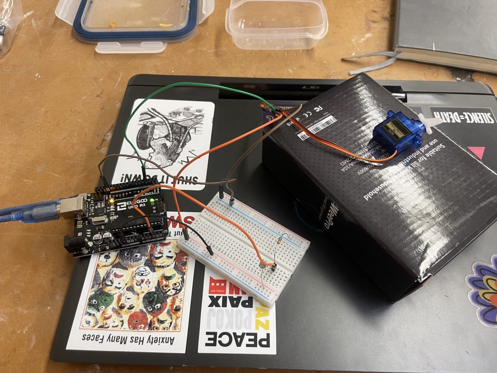
Progress photo showing testing of the servo motor.
Video
Narrative Description
Our double transducer turns rotational speed to physical heat. When something turns the knob at the left side of the board, a little motor makes a piece of yellow paper move closer to a distance reader. The distance reader makes a lightbulb heat up as the yellow paper gets closer. An LCD display shows the distance and “heat” values.
Discussion
The beginning stages of the project actually went smoothly, when we were just wiring up individual parts and configuring them. What a lot of the trouble came from was with configuring parts to each other. The ultrasonic ranger for one was extremely finicky and would refuse to work at certain points, and the Servo arm had to be placed at a certain angle and calibrated specifically.
When everything began to work together, things came down to just manual calibration, which introduced a different issue. Since we shared our code, the code was only calibrated to Caleb’s transducer, and caused issues when copied over to Lily’s. This might just call for more robust code that doesn’t have to be calibrated manually, or possible automatic calibration that we didn’t have the scope to figure out.
Something we learned was the importance of compartmentalization in the process of making a machine. Starting off, the task was extremely overwhelming. But by breaking apart the transducer into four portions that we could work on one-by-one, it was much more manageable. The different segments made it easier to conduct research, diagram, and ultimately create.
Block Diagram
Semantic Diagram
Code
//Code first records RPM of the rotary encoder and maps value to angle of servo motor
//Second, the ultrasonic ranger detects its distance from the servo motor, and the distance is mapped to the intensity of light
//Finally, the light turns on
//Map values are tuned to Caleb's transducer

//Pins:
//Rotary encoder:
//DT -> 2
//CLT -> 3
//Ultrasonic Ranger:
//trig -> 10
//echo -> 13
//Lightbulb:
//Light -> 6
//Servo Motor -> 4

//Ultrasonic ranger code from: https://www.circuitbasics.com/how-to-set-up-an-ultrasonic-range-finder-on-an-arduino/
// Timing Code from: https://courses.ideate.cmu.edu/60-223/s2023/tutorials/code-bites#blink-without-blocking

#define ENC_COUNT_REV 620
#include <Servo.h>
#include <Wire.h>
#include <Wire.h>
#include <LiquidCrystal_I2C.h>
#define trigPin 10
#define echoPin 13
#define lightPin 6

extern uint16_t twi_readFrom_timeout;
extern uint16_t twi_writeTo_timeout;
extern bool twi_readFrom_wait;
extern bool twi_writeTo_wait;

Servo doorMotor;
LiquidCrystal_I2C screen(0x27, 16, 2);

volatile long encoder_value = 0;
int interval = 1000;
int x = 123;
int motorPos = 0;
long previousMillis = 0;
long currentMillis = 0;
int lightVal = 0;
int rpm = 0;
int o = 0;
int m2 = 0;
int m = 0;

int Servo_pin = 4;
int DT_pin = 2;
int CLK_pin = 3;

void setup() {
  pinMode(DT_pin , INPUT_PULLUP);
  doorMotor.attach(Servo_pin);
  pinMode(CLK_pin , INPUT);

  Serial.begin(9600);
  pinMode(trigPin, OUTPUT);
  pinMode(echoPin, INPUT);

  pinMode(lightPin,OUTPUT);

  attachInterrupt(digitalPinToInterrupt(DT_pin), interrupt_on_pulse, RISING);

  screen.init();
  screen.backlight();
  screen.clear();
  screen.setCursor(12,1);
  screen.print("o:");
  screen.setCursor(6,0);
  screen.print("m:");
  screen.home();
  screen.print("i:");
}

void loop() {
  int motorPos = 0;
  // Record the time
  currentMillis = millis();

  if (currentMillis - previousMillis > interval) {

    previousMillis = currentMillis;

    // Calculate revolutions per minute
    rpm = (int)(encoder_value * 60 / ENC_COUNT_REV);

    int i = map (abs(rpm),0,20,0,99);
    if (i >99) {
      i = 99;
    }
    screen.setCursor(2,0);
    screen.print(abs(i));

    int motorPos = map (abs(rpm), 0, 20, 35, 80);
    // Safeguard against overload from Rotary Encoder, if motorPos is mapped to a value higher than 80 it defaults to 80
    if (motorPos > 80) {
      doorMotor.write(80);
    }
    // Regular write, causes motor to move to mapped angle
    else {
      doorMotor.write(motorPos);
    }
    delay(25);

    m = map (motorPos, 35,80,0,99);
    if (m > 99) {
      m = 99;
    }
    screen.setCursor(8, 0);
    screen.print(m);

    encoder_value = 0;
  }

  int duration, distance;

  digitalWrite(trigPin, LOW);
  delayMicroseconds(2);
  digitalWrite(trigPin, HIGH);
  delayMicroseconds(10);
  digitalWrite(trigPin, LOW);

  duration = pulseIn(echoPin, HIGH);
  distance = (duration / 2) * 0.0344;


  lightVal = map (distance,4.5,12,255,0);

  int o = map(lightVal,0,255,0,99);
  if (distance > 15) {
    lightVal = 500;
    o = 99;
    }

  screen.setCursor(14,1);
  screen.print(abs(o));

  analogWrite(lightPin,abs(lightVal));
  }

void interrupt_on_pulse() {
  int val = digitalRead(CLK_pin);
  if(val == LOW) {
    encoder_value++;
  }
  else {
    encoder_value--;
  }
}
