Peiran Ge, Quinten Staples.
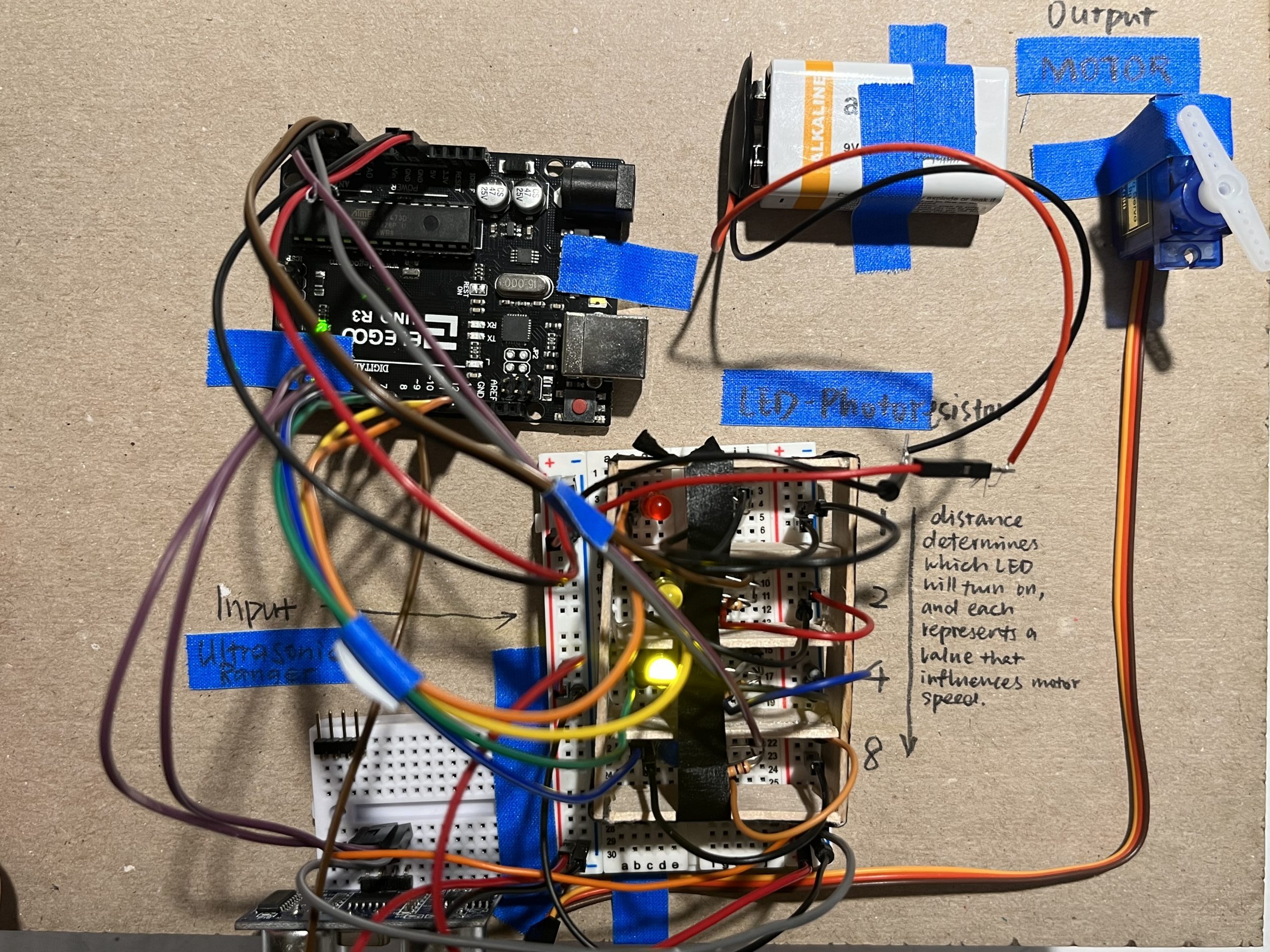
Top View of Peiran’s double transducer. Water level (bottom left), rotational speed (top right)
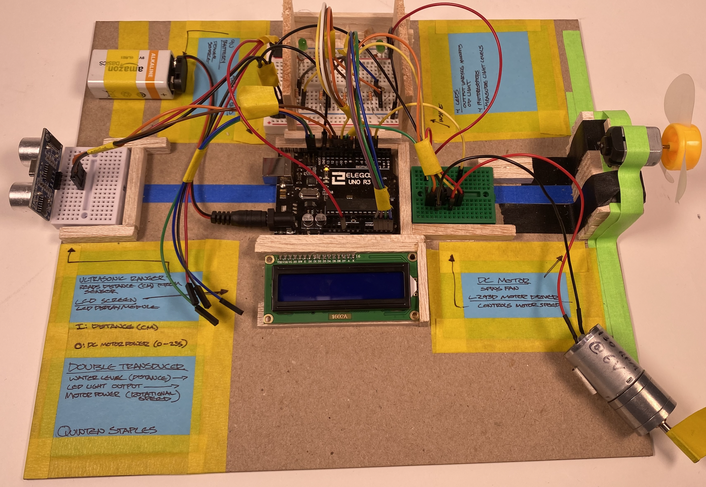
Top View of Quinten’s double transducer – Water Level (left), rotational speed (right)
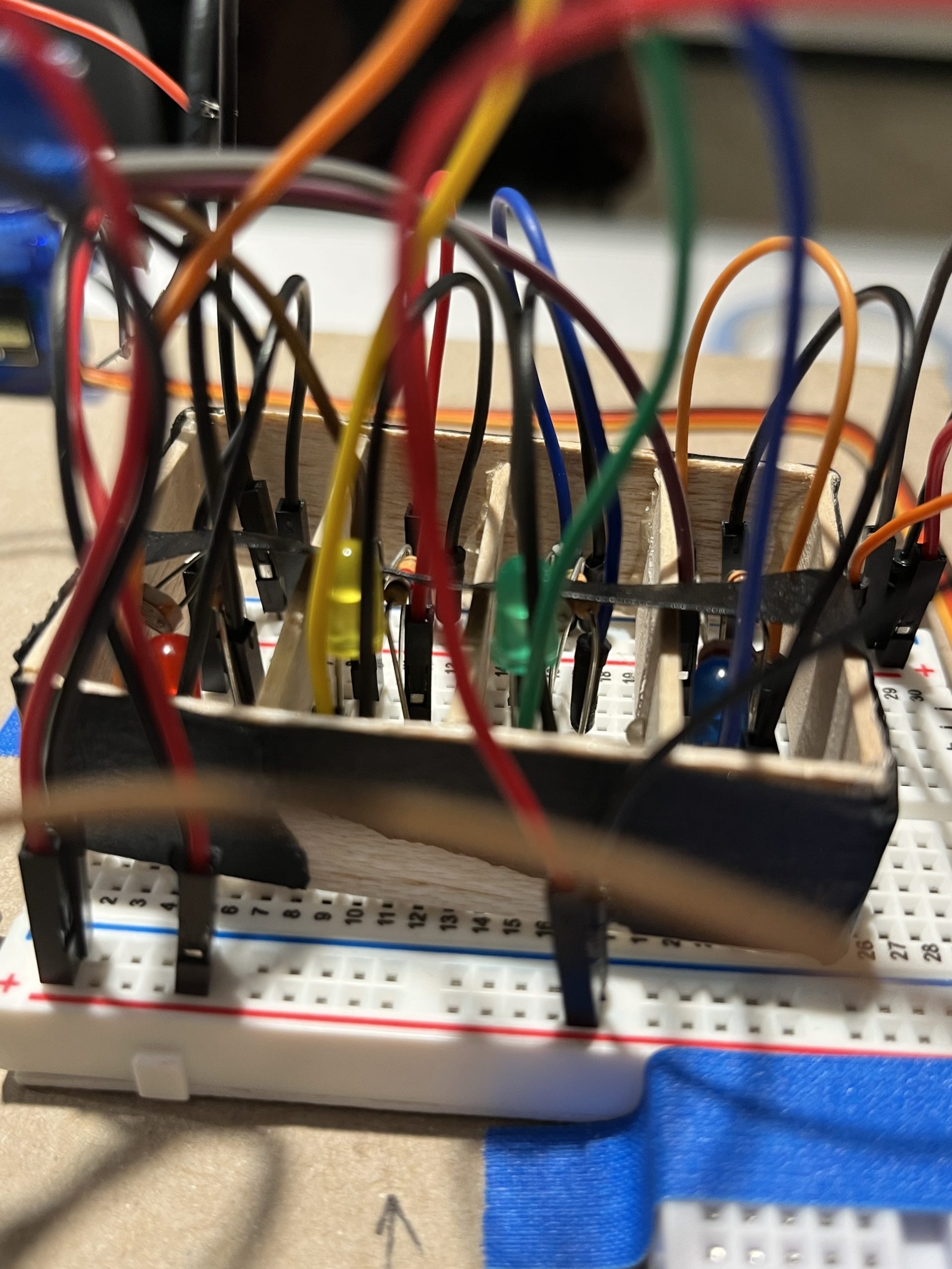
Detail on the structure that separates each photoresistor
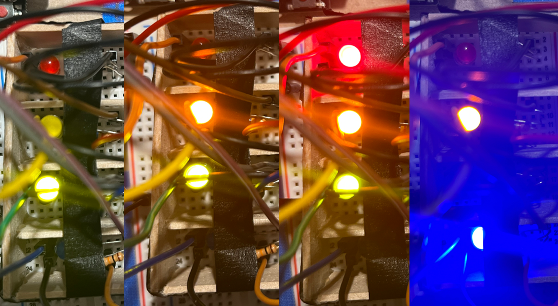
Combinations of different LED representations.
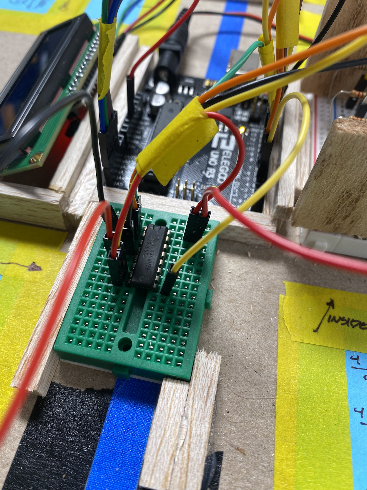
(Quinten) Image of breadboard with L293D Motor Driver and cables attaching to Arduino and DC Motor
Final Video:
Peiran
The ultrasonic ranger detects the water level, or distance to the object, which changes how 4 LEDs light up. Photoresistors then sense these light changes, and the Arduino Uno alters the motor’s rotational speed based on what the photoresistors read.
Quinten
The ultrasonic ranger works to detect distance and would probably read water levels somewhat well. The ultrasonic ranger is able to drive the 4 LEDs light output. At this point the photoresistors should pick up the light output from the LEDs and drive the DC motor’s speed. The system works up until the photoresistors and the DC motor.
Process:
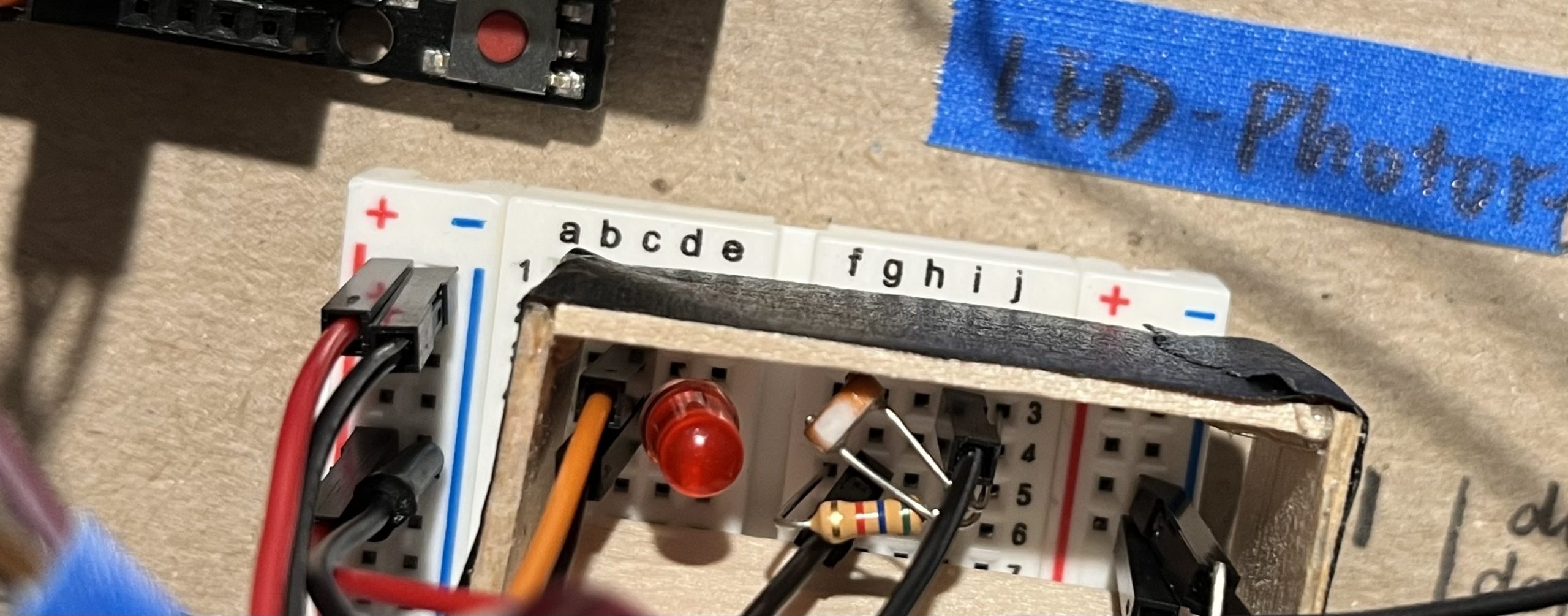
Experimenting with how to best exclude outside lighting for the photo-resistors.
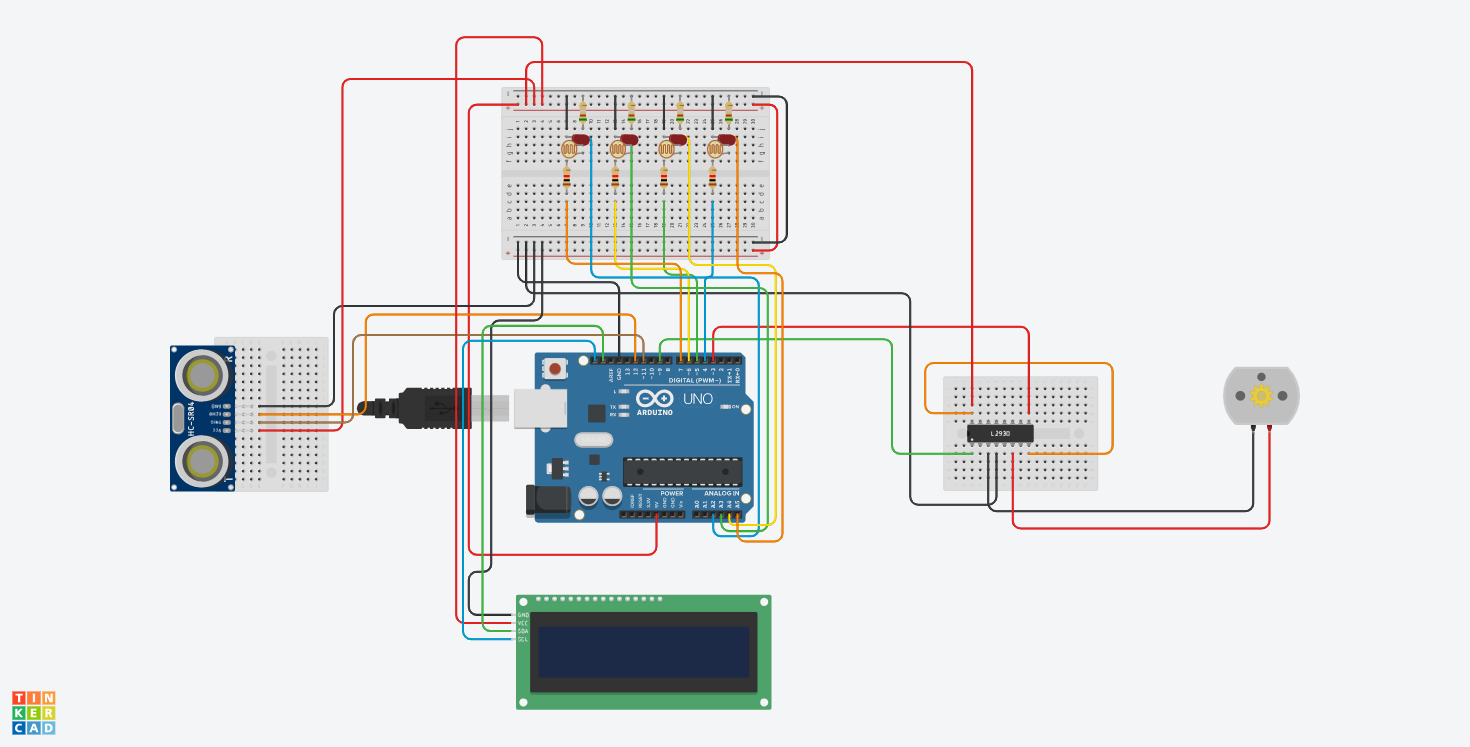
TinkerCad Model of Double Transducer- Water Level to Rotational Speed
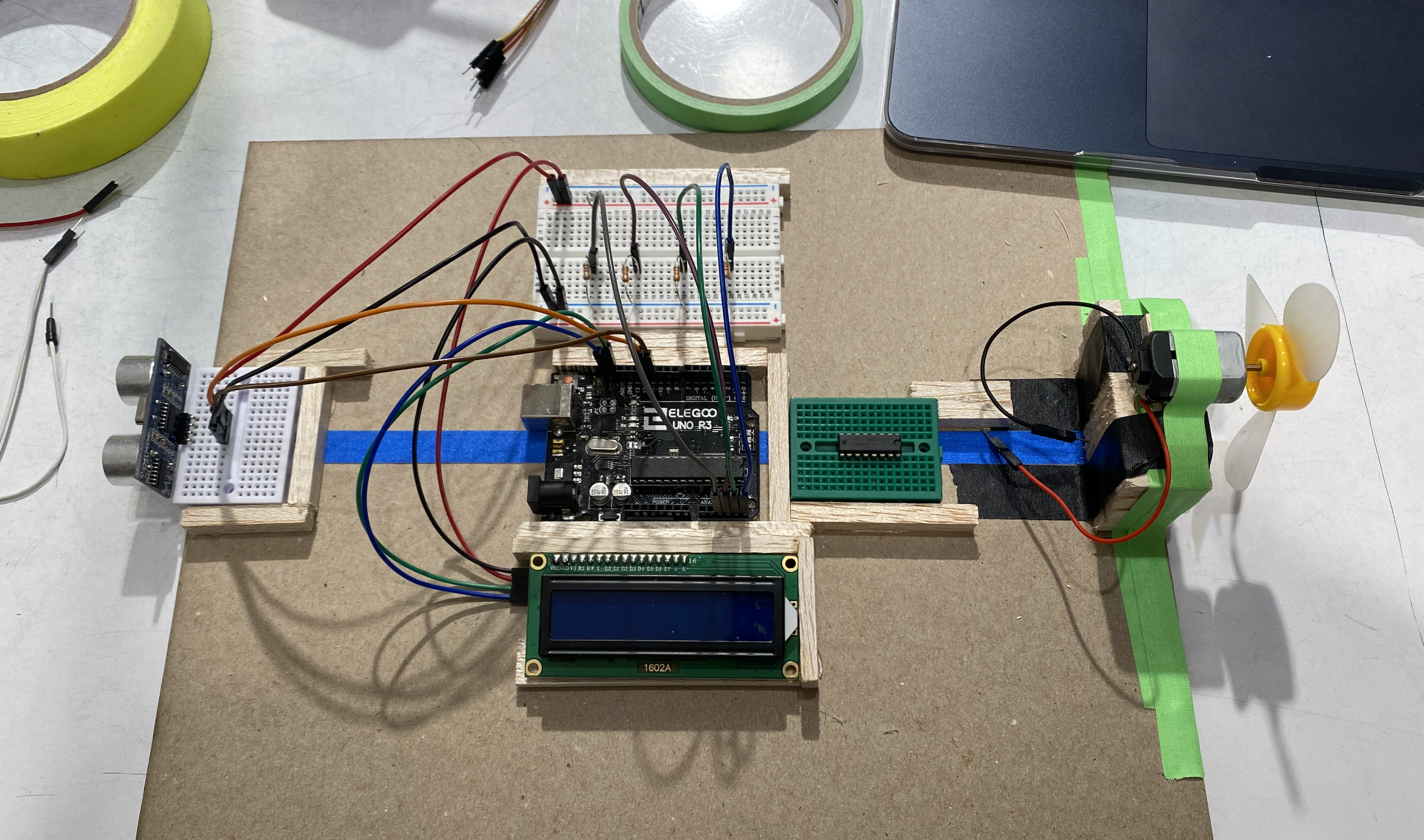
Process Image of Quinten’s double transducer. Laying out physical components to match TinkerCad diagram
Discussion:
Since our task was to only detect water levels, not manipulate them, the first part of this project was not as challenging. Both of us decided to just place the ultrasonic ranger on the board without worrying about actual water levels. We were also able to visually display the LEDs in a way that’s easy to understand and distinguish between various levels.
However, there was a lot of debugging, especially with code, and both of our projects didn’t end up successfully performing the target task. It is a bit disappointing, but overall this has been an extremely eye-opening experience. Getting the middle stage of the double transducer was more difficult than I had expected. Even with the LEDs scaling in brightness to the ultrasonic ranger’s distance readings, it was hard to get the photoresistors to read and control the motor speed the way we intended. Utilizing online documentation of past projects was a huge help in troubleshooting and figuring out our code and setup.
Diagram and Schematic:
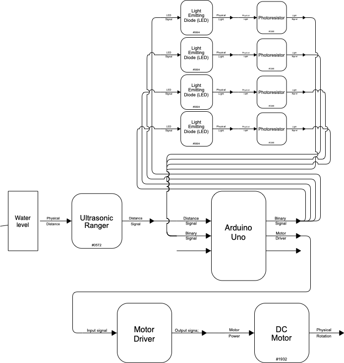
Block Diagram
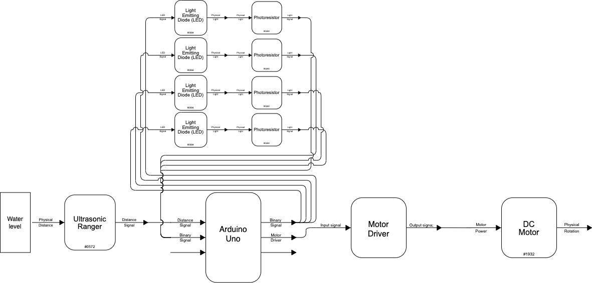
(Quinten) Block Diagram
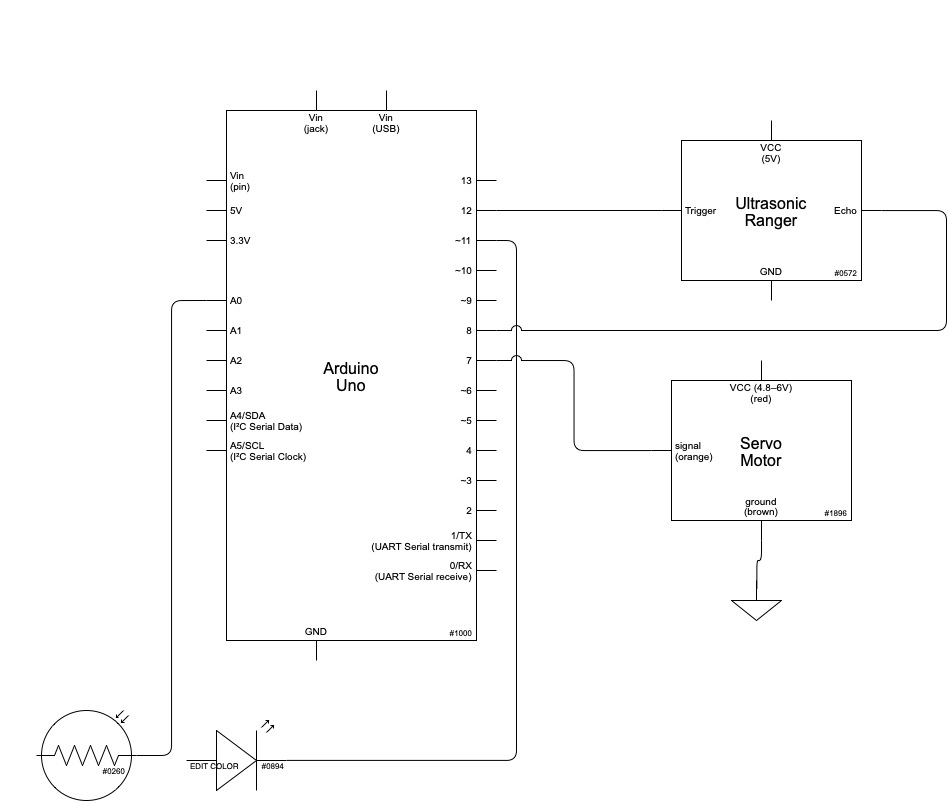
Code:
#include <Servo.h>
#include <NewPing.h>

const int trigger = 5; //ultrasonic ranger
const int echo = 4;
const int maxDist = 30; //in centimeters
const int ServoPin = 11; //Motor
const int Red = 13; //LED pins by color
const int Yellow = 12;
const int Blue = 7;
const int Green = 8;
const int Redresis = A0; //Photoresistors by color of LED
const int Yellowresis = A1;
const int Greenresis = A2;
const int Blueresis = A3;
  //Global Variables fore pin numbers.
  //Referencing to code structure guide from class website

Servo Motor;
NewPing sonar(trigger, echo, maxDist);
//Referencing tutorial pages from class website

int Dist,
    Display,
    Brightness,
    Speed;
  //Variables for input/storing information

void setup() {
  Motor.attach(ServoPin);
  pinMode(Redresis, INPUT);
  pinMode(Yellowresis, INPUT);
  pinMode(Greenresis, INPUT);
  pinMode(Blueresis, INPUT);
  pinMode(Greenresis, INPUT);

  pinMode(Red, OUTPUT);
  pinMode(Yellow, OUTPUT);
  pinMode(Green, OUTPUT);
  pinMode(Blue, OUTPUT);

  pinMode(Speed,OUTPUT);
  pinMode(ServoPin,OUTPUT);
}

void loop() {
  //detect water level
  delay(50);
  Dist = sonar.ping_cm();
  DisplayLED ();

//Photoresistor
  Brightness = 0;
int Redval;
  Redval = analogRead(Redresis);
  if (Redval >= 300) {
    Brightness += 1;
  } //referencing class website for photoresistor

int Yellowval;
  Yellowval = analogRead(Yellowresis);
  if (Yellowval >= 300) {
    Brightness += 2;
  }

int Greenval;
  Greenval = analogRead(Greenresis);
  if (Greenval >= 300) {
    Brightness += 4;
  }

int Blueval;
  Blueval = analogRead(Blueresis);
  if (Blueval >= 300) {
    Brightness += 8;
  }

//motor speed
Speed = 200/Brightness;
  Motor.write(0);
  delay(Speed);
  Motor.write(180);
  delay(Speed);
}

void DisplayLED() {
Display = Dist/2;
if (Display%2 == 1){
    digitalWrite(Red, HIGH);
  }

if (Display%4 == 2 || Display%4 == 3){
    digitalWrite(Yellow, HIGH);
  }

if ((Display-3)%8 <= 4){
    digitalWrite(Green, HIGH);
  }

if (Display >= 8){
    digitalWrite(Blue, HIGH);
  }
}