By Andres Montemayor
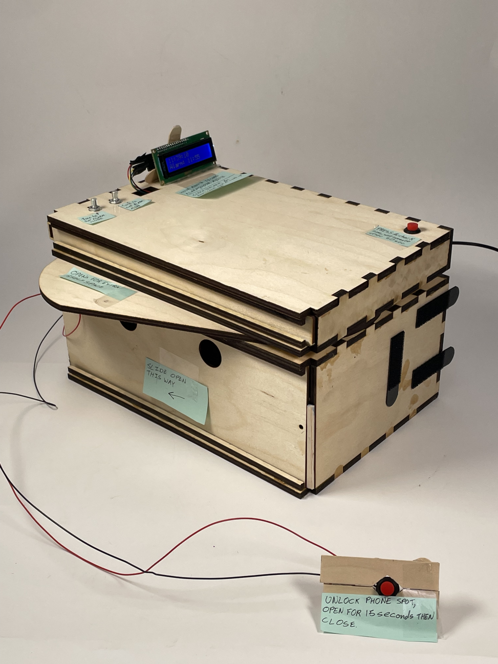
A non-destructive attachment to a campus bed that includes a clock, alarm, shelf, and lockable compartment to prevent use of phone in bed.
Demonstration of Alarm/Clock Functionality of Project. Here the alarm would have been set and when the time and alarm where the same, the buzzer would have started.
Demonstration of use of solenoid lock in bottom compartment of project. Here the compartment would be closed and the button far away from bed, forcing user to stand up and walk to press button and unlock compartment in order to access phone.

Overall photo of the developed product for proportion and scale
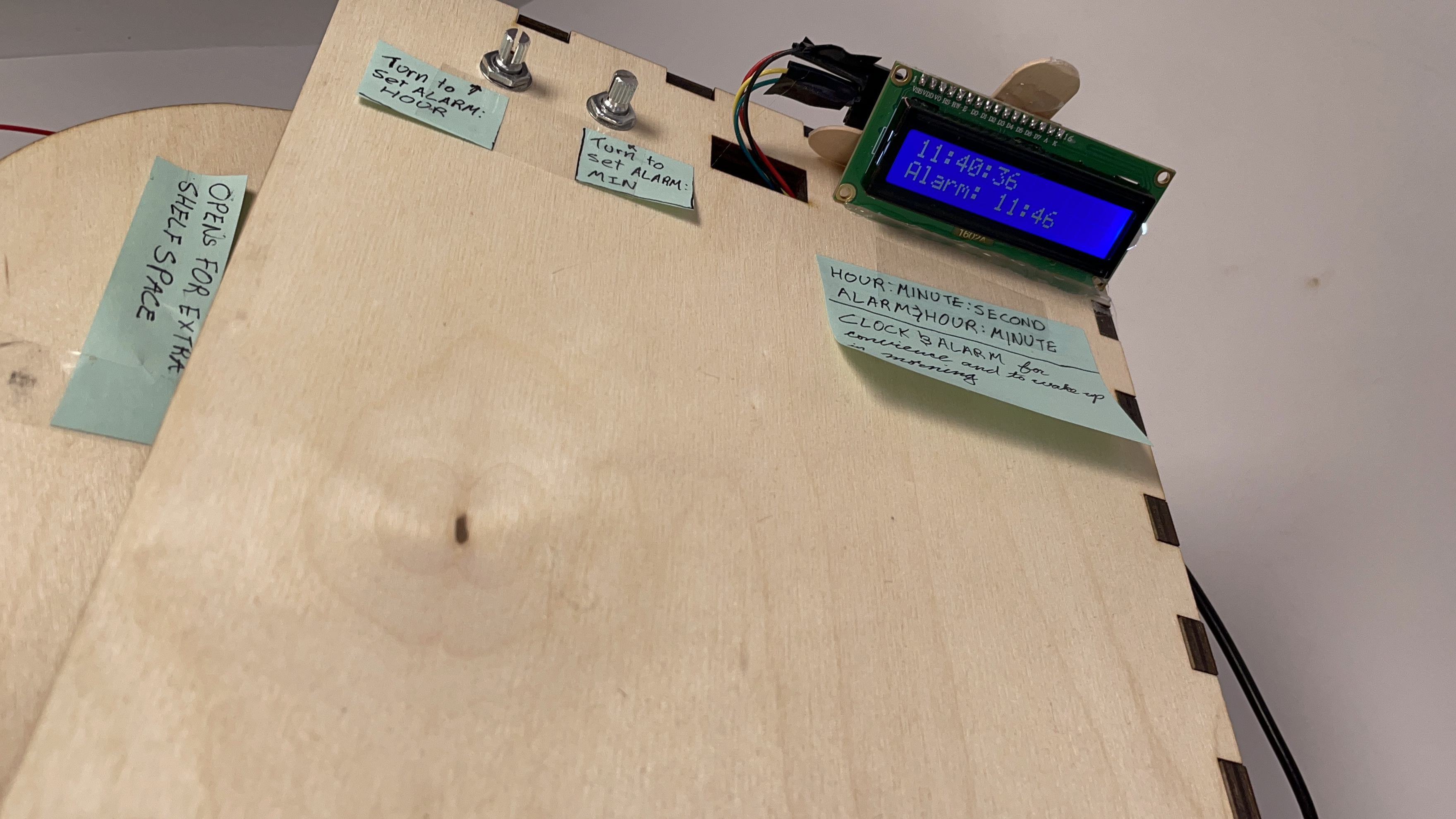
Clear visual of layout of current time and alarm set point. Also location of potentiometers to set alarm.
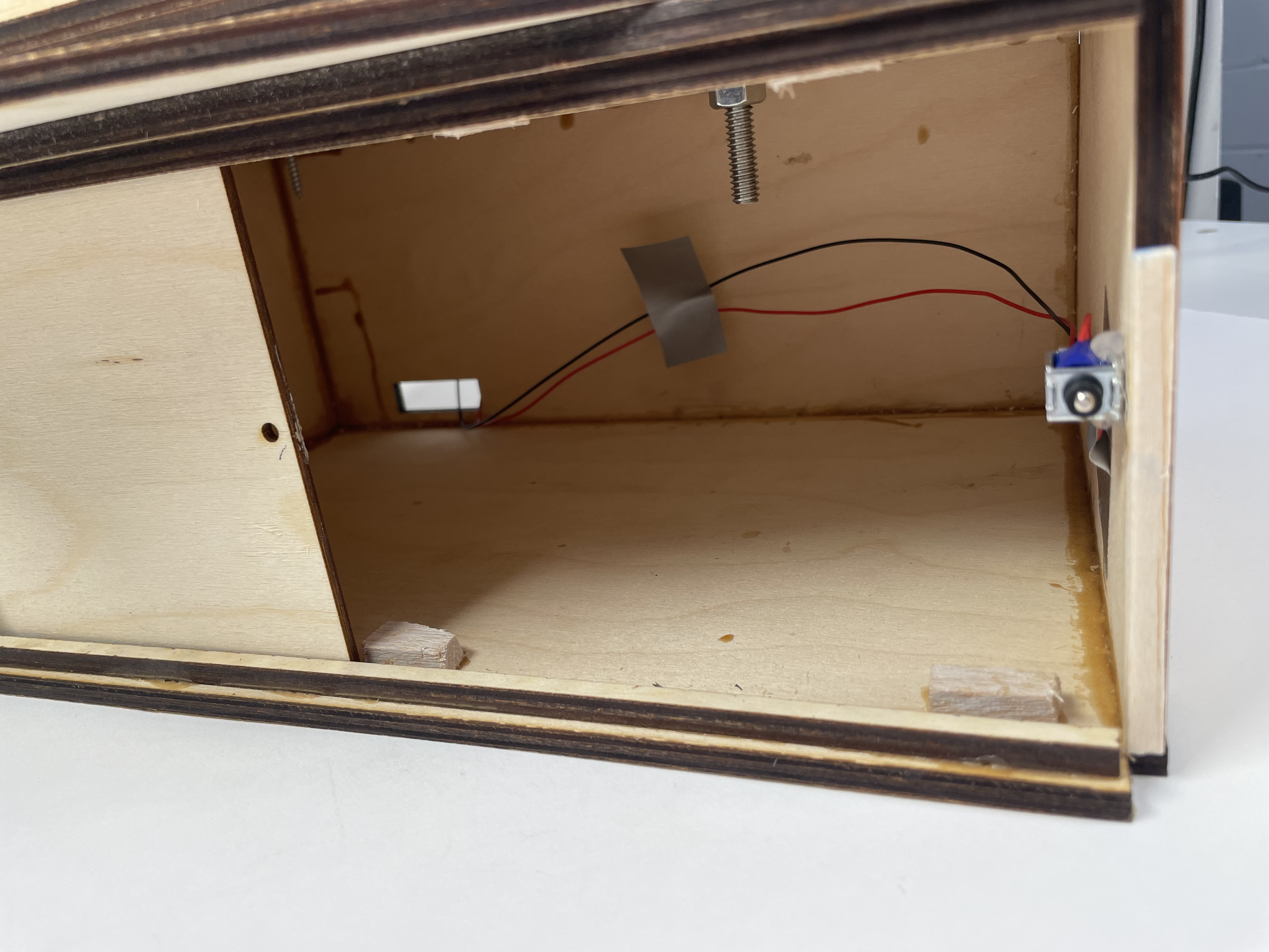
Open space to place phone to prevent use, sliding door to access the space and the 5V solenoid lock controlled by button that is separate from main system.
Process Images and Review
Throughout the design and production process of this project, there were a couple decision points that impacted the final design of my project. The first and most notable was the mode of triggering the solenoid to unlock. Due to wanting to include other subsystems within the final design, as well as manufacturing time requirements, I had to opt for a simpler mode of unlocking the solenoid lock. Originally, I was planning on creating a switch connected to a NRF24L01 wireless connector and a battery source placed in another room that ‘spoke’ to another NRF connector in the main system that told the solenoid lock to open. However, using this to operate the system would have required ordering the part, learning how to get two Arduinos to communicate correctly and I’m sure other issues not considered. Instead, as can be seen in the below image, I used a simple arcade pushbutton connected to the singular Arduino in the product connected through two wires that could be placed at a distance from the bed due to the length of those wires. This decision gave me the time to properly code, wire, and build the other parts of the project instead of struggling with a single subsystem.
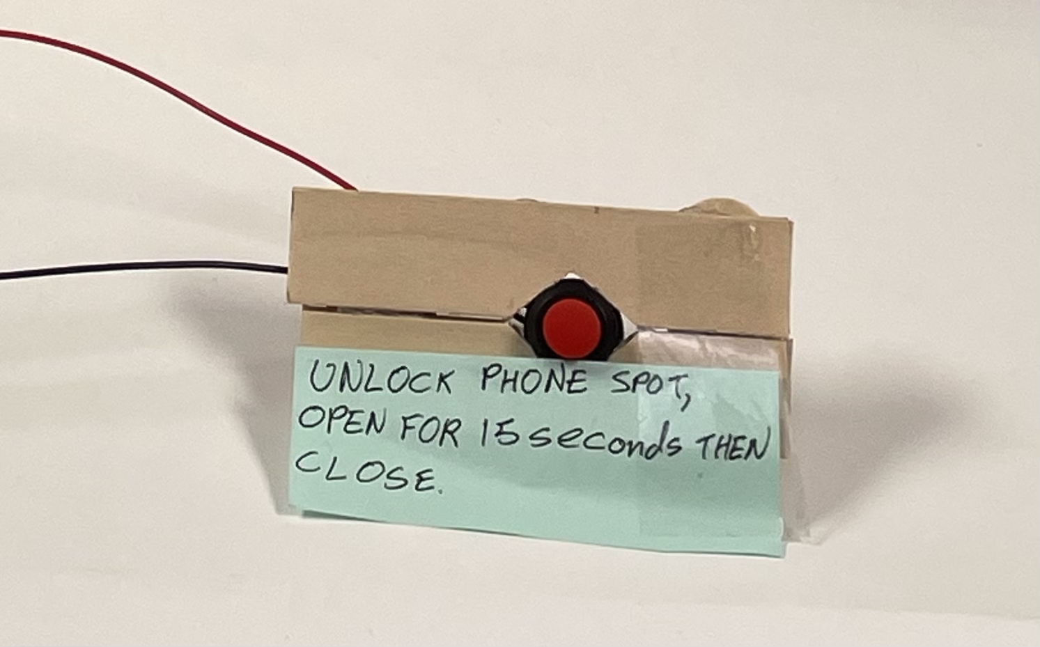
Trigger push button used to open solenoid rather than a wireless connection
Another point that I had to think about and change that significantly impacted the design of my project was the type of speaker to use in the alarm system itself. Originally, I was going to not even use a speaker at all but instead use a vibrator pancake available in the physical computing lab, however, after testing it, I realized that unless I had it physically on my body somehow it would be insufficient to wake me up in the morning. Then I decided to use a 8Ω, 0.2W speaker as that was what I was familiar with from project 1. However, I had a lot of problems with this as I would run 5 V through this speaker when it was not designed for this amount of power. This meant that even though my wiring was correct, the speaker would stop working after a couple of uses of the system. I fixed this issue by using a 8Ω, 3W speaker and a transistor to convey the alarm sound. This speaker could accept the 5V without issue and allowed my alarm to work without issue.
Process Images
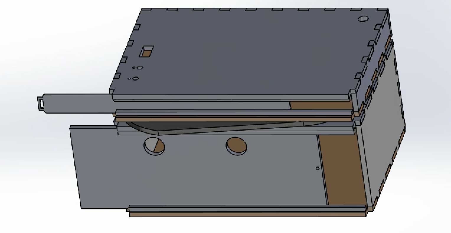
Solidworks design of project to be laser-cut out of wood. Used finger joints and glue to attach after cut.
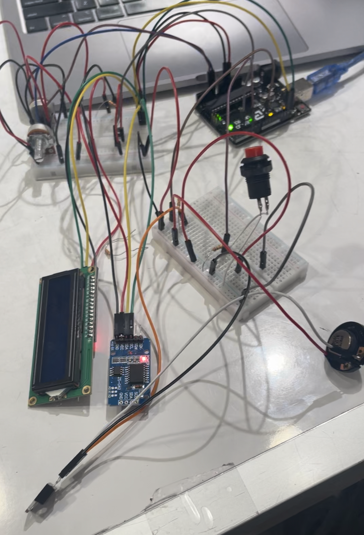
Initial prototyping of electronics to make sure code and electronics worked together correctly when using temporary connections before everything connecting through use of soldering.
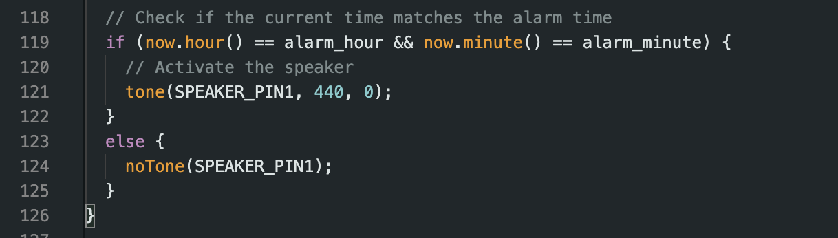
Code slice showing how speaker could be turned on or off. Was an issue at first because in original code alarm would not turn off after it had been triggered. Here, line 124 ensures that alarm only on at appropriate time.
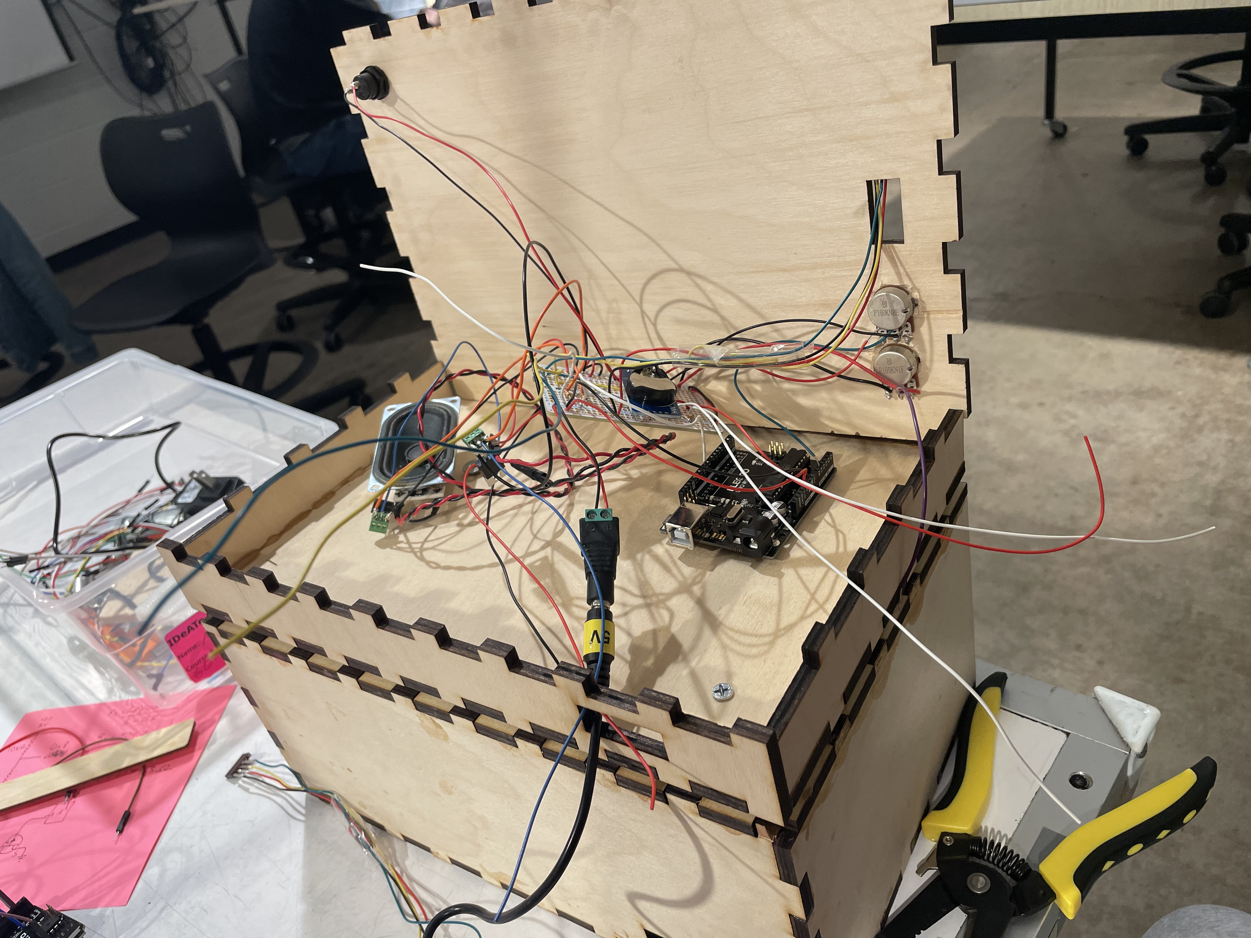
Process of putting together final product. Included soldered together electronics, and Arduino. Later top of box glued down so no wires exposed unnecessarily.
Discussion
This was a very interesting project to work on, challenging on a technical level while still allowing growth of skills such as soldering, circuits and design. There were a couple of things I would have liked to change or improve on if I had more time to work on the project before submission. In fact, two of those were pointed on in the in-class critique. The first was, “You could add some sort of long piece connected to the bottom that would go under the mattress instead of just attaching it to the side of the bed”. This was an issue I didn’t give sufficient thought to. I had planned to attach the developed system to my bed using command strips as seen in the featured image, however when I attempted that it did not work. Not providing enough support for when I placed my hand on it. I plan on creating a bar to extend from the bed frame that I can attach the bottom of the box to instead of using command strips. Another comment of interest was, “I wish the top was cushioned or padded with fabric in some way. Not sure how the wood texture would feel during sleep.” I want to put some cushioning on the free area of the object to rest my arm on in, to accomplish this I plan to buy a very small pillow and attach it to the wood using hooks.
Overall, I was satisfied with my project. it accomplished the goal I set out with, which was a bed attachment that I could rest my arm on when asleep, and in fact I added functionality to this initial problem such as a clock, alarm and phone lock to ensure I get up when I need to. The only thing I would want to spend more time on if I could is form. This is one thing I learned while working on this project. Don’t be committed to one design too early. Once I made my first CAD of the product, I immediately laser cut it out of the final material. However I think if I would have started making out of cardboard fr simpler faster manner I could have seen a lot of areas of improvement in advance. I also learned a lot about the use of transistor and their use. I think they really helped me refine my final electrical design. Making both the speaker and solenoid work a lot better as I could consistent voltage through them very easily in a very controlled manner that not using them would prevent. Finally, I do not plan on doing another iteration of this product but instead just doing a couple of easy improvements to my existing product to allow for better use. If I were to make another iteration though, there are three major things I would do. The first is wire management. I soldered all my cables in my product, however I often used soldered wires to get them off the protoboard when not necessary. I would be both easier and cleaner to place things directly on the board. Second is attachment mode, I would use an attachment rod on the bottom instead of command strips. Lastly, I would want to use a more complex way to unlock the solenoid lock. Instead of a simple push button I might use a computer generated math problem or something similar.
Technical Information

Block diagram of product showing inputs and outputs of system

Electrical schematic of and how each system is attached to Arduino
Code
/*
Morning Insurance: Assistive Device for Yourself, Project 2
By: Andres Montemayor

Description: The code below does five seperate things.
The first would be to set the alarm. By reading two seperate potentiometer inputs, it maps their values
onto a 24 hour time schedule and displays that alarm time on an I2C LCD module
The second is it reads the current time from an RTC module and also displays that on the I2C Module,
The third is it only turns on the backlight of a LCD screen for a predescribed length of time when button 1
is pressed.
The fourth is it unlocks a solenoid for a predetermined length of time when button 2 is pressed.
The fifth is when the current hour and minute on the clock is equal to the hour and minute set in the alarm
it triggers a speaker to make noise until that is no longer true. IE when the alarm changes or the minute
changes.

Pin Map:
pin        | mode   | description

POT1_PIN     | input        | potentiometer: sets alarm hour
POT2_PIN     | input        | potentiometer: sets alarm minute
buttonPin    | input        | reads when arcade button pressed, triggers backlight on LCD screen
lockButton   | input        | reads when arcade button pressed, unlocks solenoid
SPEAKER_PIN1 | output       | outputs sound at 400 Hz while alarm is triggered
SOLE_PIN     | output       | unlocks door, high or low to control if open or closed
SQL          | OUTPUT/INPUT | lcd and rtc go in here
SDA          | OUTPUT/INPUT | lcd and rtc go in here

Credit:
Used chatGPT to assist in writing code for controlling wheather or not the backlight should be on
IE lines 99 through 111.
Used example code from course website for I2C lcd displays available at
this website:https://courses.ideate.cmu.edu/60-223/s2023/tutorials/I2C-lcd,
and example code from RTC, ds3231, to help write relevent sections
Used library from adafruit on RTC_DS3231 available at this website:https://github.com/adafruit/RTClib
*/


//modules to control different subsystems
#include <Wire.h>
#include <LiquidCrystal_I2C.h>
#include <RTClib.h>

//Initialize the LCD library with the I2C address, number of columns and rows. call it lcd
LiquidCrystal_I2C lcd(0x27, 16, 2);

// Initialize the RTC module object and call it rtc to control from now on
RTC_DS3231 rtc;

// Initialize the pins for the potentiometers, buttons, speaker, and solenoid
const int POT1_PIN = A0;
const int POT2_PIN = A1;
const int SPEAKER_PIN1 = 9;
const int buttonPin = 2;
const int lockButton = 5;
const int SOLE_PIN =11;

//Initialize variables used throughout code for time, timers, and bools
bool isButtonPressed = false;
bool isLightOn = false;
bool isDoorOpen = false;

int alarm_hour = 0;
int alarm_minute = 0;

unsigned long lastOnTime = 0;
unsigned long lastUnlockTime = 0;

void setup() {
  // Initialize the LCD display
  lcd.init();

  // Initialize the RTC module
  Wire.begin();
  rtc.begin();

  // Set the current time, only do if need to replace battery in RTC module.
  //rtc.adjust(DateTime(2023, 2, 27, 9, 50, 00));  //year,month,day,hour,min,sec

  // Set the pins for the potentiometers, vibrator, speaker and solenoid
  pinMode(buttonPin, INPUT);
  pinMode(POT1_PIN, INPUT);
  pinMode(POT2_PIN, INPUT);
  pinMode(SPEAKER_PIN1, OUTPUT);
  pinMode(lockButton,INPUT);
  pinMode(SOLE_PIN,OUTPUT);
}

void loop() {
  //if button pressed open solenoid and start a timer
  if (digitalRead(lockButton) == LOW) {
    lastUnlockTime = millis();
    isDoorOpen = true;
    digitalWrite(SOLE_PIN,HIGH);
  }
  //if 15 seconds have passed close solenoid
  if (millis()-lastUnlockTime >= 15000) {
    digitalWrite(SOLE_PIN,LOW);
  }
  //if button pressed and backlight off, turn it on and start a timer
  if (digitalRead(buttonPin) == LOW && !isLightOn) {
    isButtonPressed = true;
    lastOnTime = millis();
    lcd.backlight();
    isLightOn = true;
  }

  // Check if the LCD screen is on and the timer is off
  if (isButtonPressed && (millis() - lastOnTime) >= 20000) {
    lcd.noBacklight();
    isButtonPressed = false;
    isLightOn = false;
  }

  // Print the current time to the LCD display
  DateTime now = rtc.now();
  lcd.setCursor(0, 0);
  lcd.print(now.hour(), DEC);
  lcd.print(":");
  if (now.minute() < 10) {
    lcd.print("0");
  }
  lcd.print(now.minute(), DEC);
  lcd.print(":");
  if (now.second() < 10) {
    lcd.print("0");
  }
  lcd.print(now.second(), DEC);

  // Read the values of the potentiometers to set the alarm
  int pot1_value = analogRead(POT1_PIN);
  int pot2_value = analogRead(POT2_PIN);
  alarm_hour = map(pot1_value, 0, 1023, 0, 23);
  alarm_minute = map(pot2_value, 0, 1023, 0, 59);

  // Print the alarm time to the LCD display
  lcd.setCursor(0, 1);
  lcd.print("Alarm: ");
  if (alarm_hour < 10) {
    lcd.print("0");
  }
  lcd.print(alarm_hour);
  lcd.print(":");
  if (alarm_minute < 10) {
    lcd.print("0");
  }
  lcd.print(alarm_minute);

  // Check if the current time matches the alarm time
  if (now.hour() == alarm_hour && now.minute() == alarm_minute) {
    // Activate the speaker
    tone(SPEAKER_PIN1, 440, 0);
  }
  else {
    //otherwise turn off speaker
    noTone(SPEAKER_PIN1);
  }
}