This is a redefined bag, personalized to cater to my schedule requirements.
Video of it working:
This is a video of the bag in practice. According to my schedule for Thursday, pockets one, two and, three are lit up ad only when all the three pockets are filled with the required things the LED strips turn off, indicating that my bag is packed and I am ready to go for the day.
Product photos:
Overall photo for proportion and scale
Side view of the bag
Detail photos:
Housing details: Image showing LED strip placed in the center on top of every pocket. The LCD screen in popping out from the middle as well to display RTC. This image also focuses on the detail of how the base of the pocket is fabricated with an open box using plywood where the IR break beam sensors are screwed to the side to detect an object intervention. The box has holes on the backside for the wires to follow a path from one pocket to the next till the last pocket to connect to the Arduino.
A close-up of how it looks inside. The LCD screen is stitched to the bag from inside and the open box is placed at the bottom of the pocket with wires pushed to the side so that there is clear space for interaction.
Usage photos:
According to the day’s schedule the bag has certain pocket LED strip lights on indicating that the specific items are missing and the pockets need to be filled, to make my bag ready for the day.
As all the pockets are filled the red indication light turns of implementing I am ready for the day
The bag is conditioned to work from 6:00 am to 8:00 am which is my regular time to arrange my bag for the day. So that during the day if I take out stuff from my bag the LED strip doesn’t glow back as the purpose of the bag is not to indicate whether the pocket is full or empty but rather to make the morning routine simpler and more efficient for me.
Process images and review:
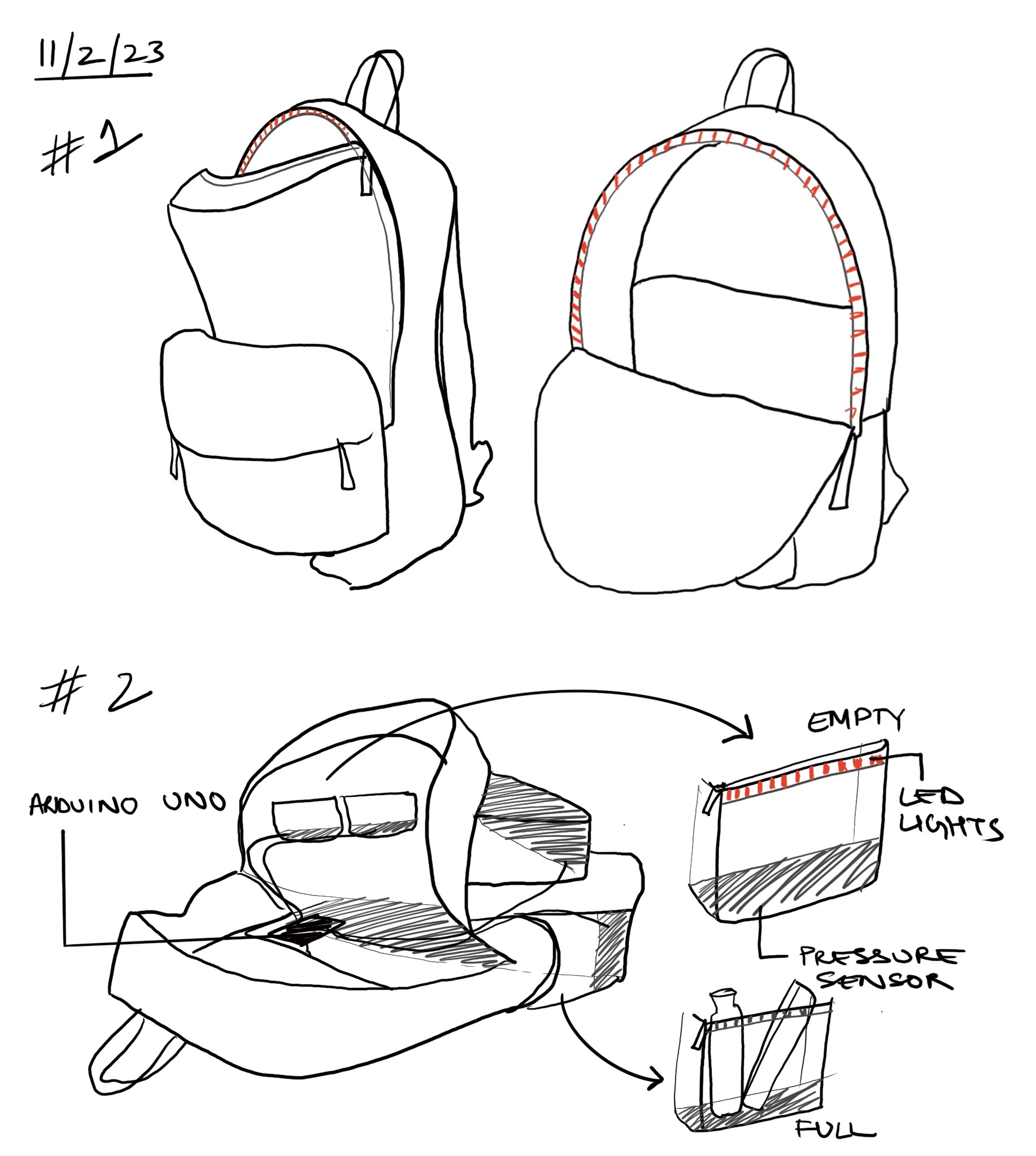
This is my initial ideation of the project where I thought of the bag as a smart bag where the detection of the object was decided through pressure sensor. Through the initial making of the project I realized that the pressure sensor will not be very consistent and reliable as it is very small and sensitive. As the bag is soft the pressure sensor could actually get activate by any surface of the bag. This was a very initial exploration but I feel it had a big change in my idea as I had a lot of add-ons which I initially didn’t think of.
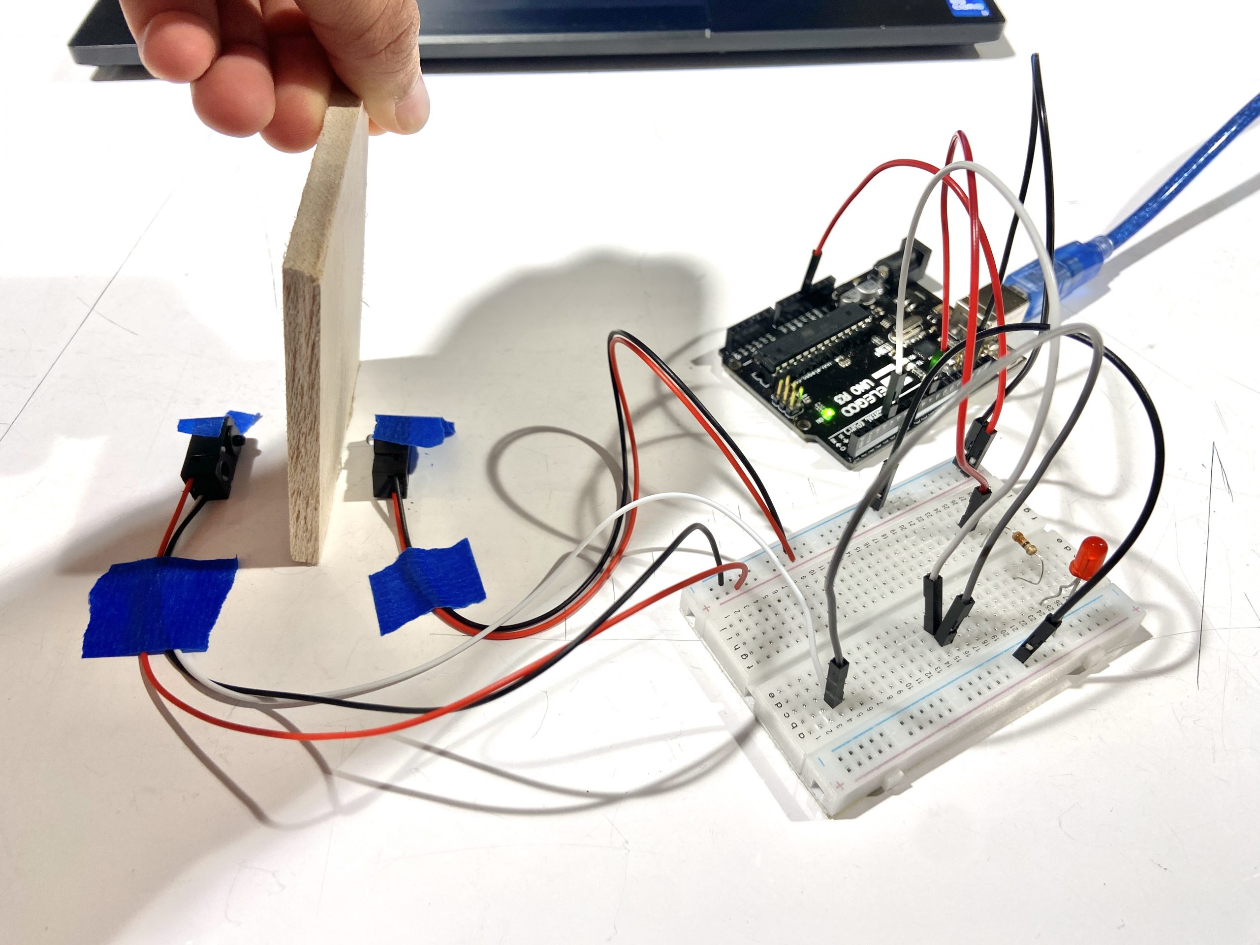
I opted for a step-by-step process for my project. This was my first step to explore the IR Break beam sensor (the sensor I chose to work with instead of the pressure sensor) by experimenting with the basic obstacle detecting method and using a LED for indication.
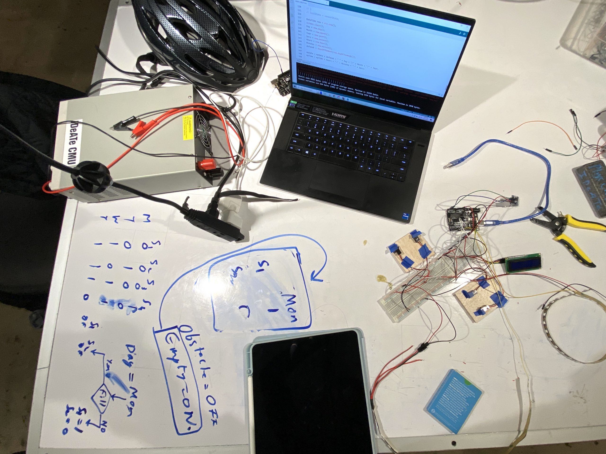
During the process, since I was including one set of sensor in each pocket of the bag I coded all four sensors individually and then combined the code for all. The step where I had to condition the system to work according to my schedule was a little confusing for me as there where so many conditions I needed to keep in mind, so through making flow charts and diagrammatic references I managed to code it all.
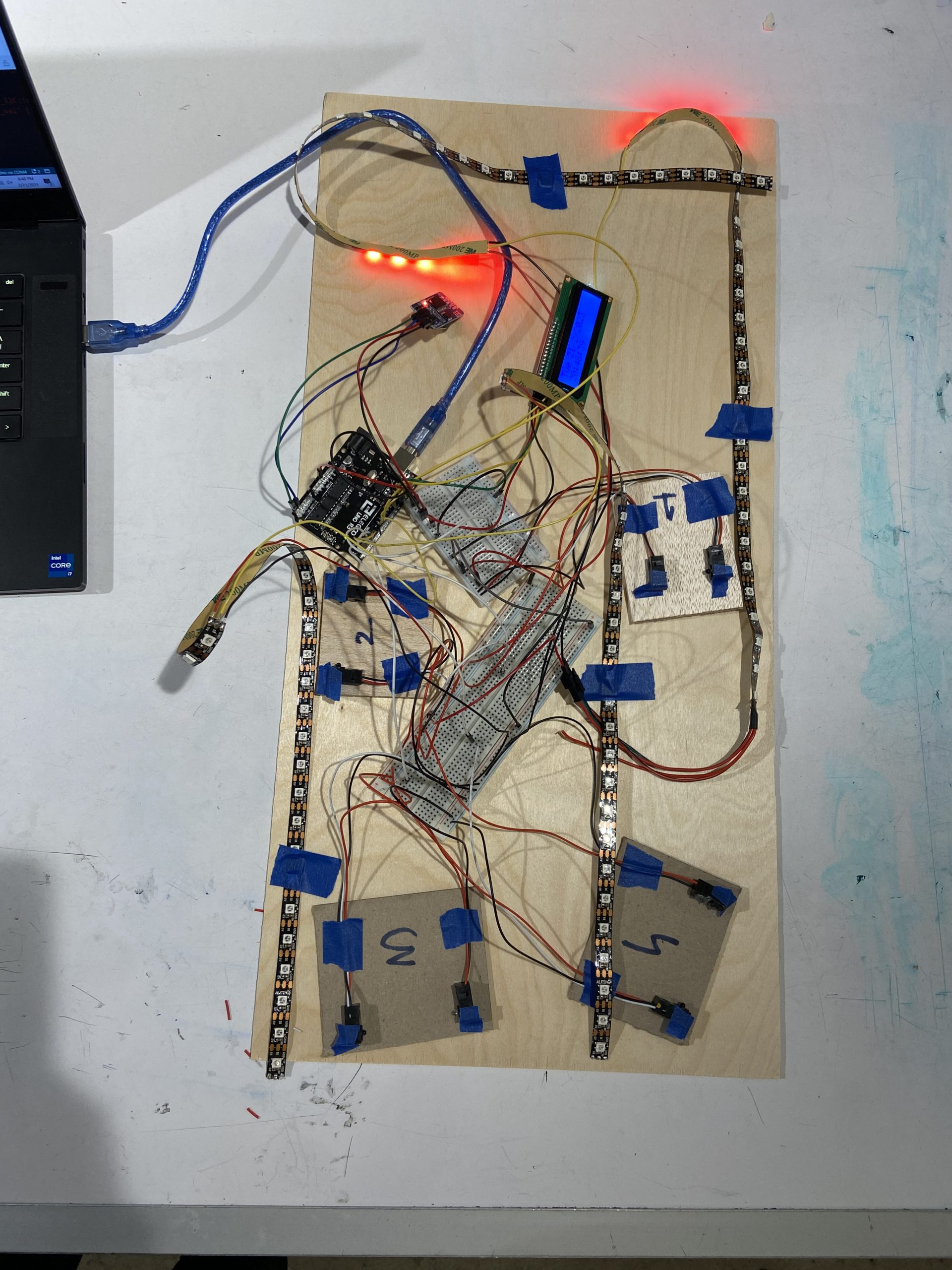
Since, I didn’t have the bag for the first week, I targeted myself to complete the electrical part which was finishing the coding for the whole system in relation to the RTC. This image shows my prototype model for the four sensors as four pockets working with respective LEDs in relation to the RTC following my schedule.
The next step was to measure each bag pocket and fabricate the base where the sensors will be installed and so that each pocket has support to avoid any bag fabric intervention. I measured the bases of each pocket and sensor sizes using calipers for accuracy. It was difficult to reach till the bottom of the bag and so since the bag was flexible I folded the pockets outward to measure the size, however I felt it didn’t give me exact dimensions and I had to sort of eyeball ay some points at the stitches didn’t align entirely.
Also, it was my first time working with plywood and I think it was a little challenging as in the very first place I made the boxes to align at the edges instead of making finger joints for the corner as that challenged me to be extra careful with the craft.
This image shows my process of making each base, gluing the edges using the tite bond wood glue and clamping the edges for half an hour. This made the whole process very slow as it was very time consuming. The other challenge was that I had to be very careful aligning the edges as I had to make sure I clamped them at exact 90 degrees.
After fabricating the boxes I placed each box in the pockets respectively however the screws available where only 20 mm which increased the size and thus there was no margin to fit the box in and thus I had to cut the extra screw using the hacksaw. To avoid the friction I also oiled the hacksaw, it was a new discovery for me.
After placing all the boxes and doing the wiring in the bag, it became very messy as it was very chaotic than I had thought and made it very difficult for me to keep a track. The wiring was majorly wiring and groung however there were sensor wires and LED strip data pins that had to be connected. During this porcess I also had to be very careful that the wires are long enough to reach to the end of the bag. With a few wires my estimation was wrong and I actually had to solder couple of wires in the bag which was very hard.
The fabrication was personally more difficult than coding the system for me. After making the device there was some wiring issue that I came across and wasn’t able to figure out which sadly crashed my device and the sensors stopped working. However to make the system work and convey my idea I tried to do a quick fix by making a prototype using the proximity sensor.
I added proximity sensors for prototyping and coded the system to work according to analog reading. The system worked as expected and was successfully running.
Discussion:
One critique I received during the in-class critique was about the limited time frame during which the project operates. The commenter felt that the restriction to operate only between 6:00 am to 8:00 am was a really sensitive consideration. In response, I feel that the project was designed to fit my personal schedule and needs, but I acknowledged that it may not be ideal for everyone. Another critique I received was about the use of IR break beam sensors. The commenter was unfamiliar with this type of sensor and questioned its reliability. They also suggested an E textiles class which could help me with the skills to incorporate my sensors into the bag so that I can get rid of the extra box like base that I had to create for the sensors. I feel how the sensors work and the advantages of using them in this project, such as their ability to detect object presence accurately and their low power consumption is beneficial. I also noted that there are other types of sensors that could be used in a similar project like pressure sensor, and that the choice of sensor depends on the specific design of the bag, like the pocket sizes and bag type(soft or stiff). I am pleased with the project’s overall outcome. It succeeded in helping me create a strategy that makes sure I have everything I need in my bag before leaving for the day. The usage of the IR break beam sensors, which have shown to be dependable and accurate, has particularly impressed me. I gained a lot of coding and technological knowledge while working on this project. The code for the RTC and LCD screen was simple, however initially I had trouble configuring the IR break beam sensors. Yet with perseverance and investigation, I was able to get beyond the difficulties and make them work. While I find them to be both tough and satisfying, I would like to keep working on projects that involve more condition-based applications in the future. Even though I am pleased with the project’s current state, I would like to keep tweaking and enhancing it. One potential improvement would be if creating the same bag I would think more about the wire connection and how I can improve the fabrication design so that I can avoid the wire chaos and have a more organized layout, which would also help in the sensors having any random intervention, making them more efficient. I would also like to explore other types of sensors that could be used in conjunction with the IR break beam sensors to provide more comprehensive information about the contents of the bag. Ultimately, my goal is to create a smart bag that can help users stay organized and prepared for the day ahead.
Technical Information:
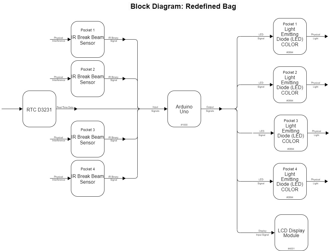
Block diagram of the device showing inputs and outputs of the system
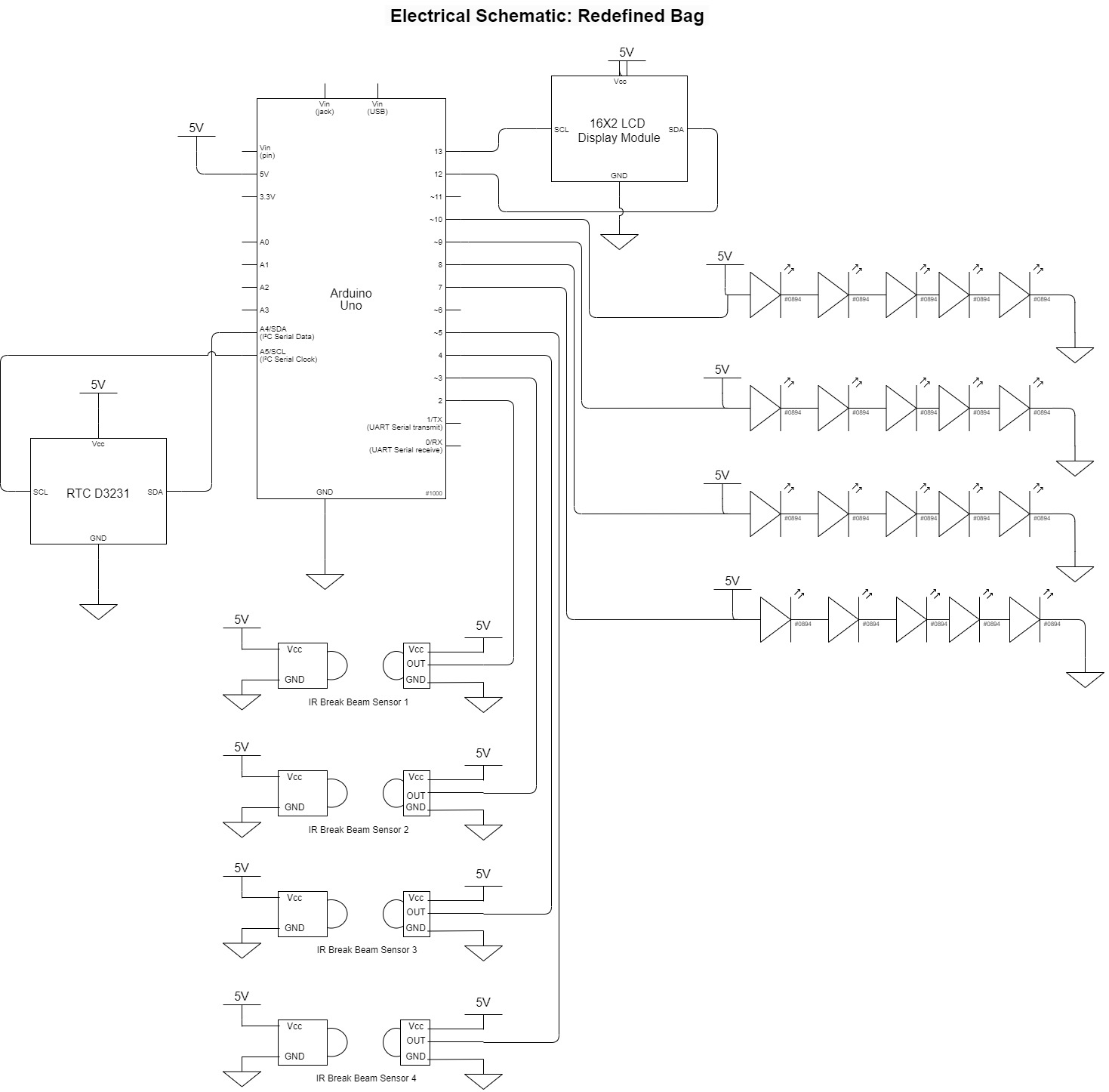
Electrical schematic of and how each component is attached to Arduino
Code:
// My Day Duffle
// By: Juhi Kedia

// The following code is intended to indicate whether the bag is ready for the day or not
// according to my schedule. There is a RTC running in the code which tracks the day, date and time.
// It can also be manually adjusted for testing. The LCD screen is coded to display the information
// provided from the RTC so that the clock is visible to the user. There are 4 IR break beam sensors
// attached to 4 inputs which detect whether the object is present or not. There is an emitter and
// a receiver in the IR break beam sensor so if the object is present the receiver doesn't receive light
// which indicates the LEDs attached to the sensor to either turn on or off accordingly. This thus indicates
// whether stuff in bag is present or not. This is conditioned to work between 6:00 am to 8:00 am
// so that the LEDs don't turn on and off during the day as it can become very distracting to carry a bag like that.
// The code has different conditions for each sensor and LED strip respectively according to the day of the week
// in this case for me according to my schedule.

// Pin Mapping:
//     Arduino Pin  /  Role  /   Description
//       2            Input    Pocket 1 sensor
//       3            Input    Pocket 2 sensor
//       4            Input    Pocket 3 sensor
//       5            Input    Pocket 4 sensor
//       7            Output   Pocket 1 LED strip
//       8            Output   Pocket 2 LED strip
//       9            Output   Pocket 3 LED strip
//       10           Output   Pocket 4 LED strip

// Reading the IR break beam sensor and turning on a LED code inspiration from:
// https://www.sensingthecity.com/using-ir-breakbeam-senors-to-detect-the-fullness-of-a-trash-bin-and-change-rgb-color-accordingly/

// Understanding how the RTC needs to be coded and how the information from the RTC
// can be displayed on the LCD screen code inspiration from:
// https://www.youtube.com/watch?v=aJcncPB0GHg


#include <Wire.h>
#include <LiquidCrystal_I2C.h>
#include <RTClib.h>
#include <PololuLedStrip.h>

// setup PololuLedStrip and set each strip to a pin number
PololuLedStrip<7> ledStrip1;
PololuLedStrip<8> ledStrip2;
PololuLedStrip<9> ledStrip3;
PololuLedStrip<10> ledStrip4;

#define LED_COUNT 5

RTC_DS3231 rtc;

#define SENSORPIN1 2
#define SENSORPIN2 3
#define SENSORPIN3 4
#define SENSORPIN4 5

int sensorState1 = 0, lastState1 = 0;
int sensorState2 = 0, lastState2 = 0;
int sensorState3 = 0, lastState3 = 0;
int sensorState4 = 0, lastState4 = 0;

rgb_color on[LED_COUNT];
rgb_color off[LED_COUNT];


char daysOfTheWeek[7][4] = {
  "Sun",
  "Mon",
  "Tue",
  "Wed",
  "Thu",
  "Fri",
  "Sat"
};

int Day;
int Month;
int Year;
int Secs;
int Minutes;
int Hours;

String dofweek;  //days of week
String myDate;
String myTime;
String dow;

LiquidCrystal_I2C screen(0x27, 16, 2);


void setup() {
  screen.init();
  screen.backlight();
  Serial.begin(9600);
  screen.begin(16, 2);
  delay(3000);

  // initialize the sensor pin as an input:
  pinMode(SENSORPIN1, INPUT);
  pinMode(SENSORPIN2, INPUT);
  pinMode(SENSORPIN3, INPUT);
  pinMode(SENSORPIN4, INPUT);

  digitalWrite(SENSORPIN1, HIGH);  // turn on the pullup
  digitalWrite(SENSORPIN2, HIGH);  // turn on the pullup
  digitalWrite(SENSORPIN3, HIGH);  // turn on the pullup
  digitalWrite(SENSORPIN4, HIGH);  // turn on the pullup

  Serial.begin(9600);

  for (int i = 0; i < LED_COUNT; i++) {
    // on is red
    on[i] = rgb_color(255, 0, 0);
  }
  for (int i = 0; i < LED_COUNT; i++) {
    // off is clear/nothing
    off[i] = rgb_color(0, 0, 0);
  }

  if (!rtc.begin()) {
    Serial.println(" RTC Module not Present");
    while (1)
      ;
  }
  if (rtc.lostPower()) {
    Serial.println("RTC power failure, reset the time!");
    // automatically sets the RTC to the date & time on PC this sketch was compiled
    rtc.adjust(DateTime(F(__DATE__), F(__TIME__)));
    // rtc.adjust(DateTime(2023, 2, 20, 3, 0, 0));
  } else {
    rtc.adjust(DateTime(F(__DATE__), F(__TIME__)));
    // adjusts the rtc manually for demo
    // rtc.adjust(DateTime(2023, 2, 23, 6, 0, 0));
  }
}


void loop() {
  // read the state of the sensors:
  sensorState1 = digitalRead(SENSORPIN1);
  sensorState2 = digitalRead(SENSORPIN2);
  sensorState3 = digitalRead(SENSORPIN3);
  sensorState4 = digitalRead(SENSORPIN4);
  // Serial.println(sensorState1);

  DateTime now = rtc.now();
  screen.clear();
  Day = now.day();
  Month = now.month();
  Year = now.year();
  Secs = now.second();
  Hours = now.hour();
  Minutes = now.minute();
  dofweek = daysOfTheWeek[now.dayOfTheWeek()];

  myDate = myDate + dofweek + " " + Day + "/" + Month + "/" + Year;
  myTime = myTime + Hours + ":" + Minutes + ":" + Secs;

  // send to serial monitor
  Serial.println(dofweek);
  Serial.println(myDate);
  Serial.println(myTime);

  //print on lcd
  screen.setCursor(0, 0);
  screen.print(myDate);
  screen.setCursor(0, 1);
  screen.print(myTime);
  myDate = "";
  myTime = "";
  delay(1000);

  // check if the sensor beam is broken
  // if it is, the sensorState is LOW:
  // turn LED off:
  // Red (turn the red LED off):

  if (now.hour() >= 6 && now.hour() < 8) {
    if (dofweek == "Mon") {
      if ((sensorState1 == LOW) && (sensorState4 == LOW)) {
        ledStrip1.write(off, LED_COUNT);
        ledStrip2.write(off, LED_COUNT);
        ledStrip3.write(off, LED_COUNT);
        ledStrip4.write(off, LED_COUNT);

      } else {
        // On (LED on):
        ledStrip1.write(on, LED_COUNT);
        ledStrip2.write(off, LED_COUNT);
        ledStrip3.write(off, LED_COUNT);
        ledStrip4.write(on, LED_COUNT);
      }
    }

    if (dofweek == "Tue") {
      if ((sensorState1 == LOW) && (sensorState2 == LOW)) {

        ledStrip1.write(off, LED_COUNT);
        ledStrip2.write(off, LED_COUNT);
        ledStrip3.write(off, LED_COUNT);
        ledStrip4.write(off, LED_COUNT);


      } else {
        // On (LED on):
        ledStrip1.write(off, LED_COUNT);
        ledStrip2.write(off, LED_COUNT);
        ledStrip3.write(on, LED_COUNT);
        ledStrip4.write(on, LED_COUNT);
        // Serial.println("sensorState1");
      }
    }


    if (dofweek == "Wed") {
      if ((sensorState1 == LOW) && (sensorState3 == LOW) && (sensorState4 == LOW)) {
        ledStrip1.write(off, LED_COUNT);
        ledStrip2.write(off, LED_COUNT);
        ledStrip3.write(off, LED_COUNT);
        ledStrip4.write(off, LED_COUNT);

      } else {
        // On (LED on):
        ledStrip1.write(on, LED_COUNT);
        ledStrip2.write(off, LED_COUNT);
        ledStrip3.write(on, LED_COUNT);
        ledStrip4.write(on, LED_COUNT);
      }
    }

    if (dofweek == "Thu") {
      if ((sensorState1 == LOW) && (sensorState2 == LOW) && (sensorState3 == LOW)) {
        ledStrip1.write(off, LED_COUNT);
        ledStrip2.write(off, LED_COUNT);
        ledStrip3.write(off, LED_COUNT);
        ledStrip4.write(off, LED_COUNT);

      } else {
        // On (LED on):
        ledStrip1.write(on, LED_COUNT);
        ledStrip2.write(on, LED_COUNT);
        ledStrip3.write(on, LED_COUNT);
        ledStrip4.write(off, LED_COUNT);
      }
    }

    if (dofweek == "Fri") {
      if ((sensorState1 == LOW) && (sensorState2 == LOW)) {
        ledStrip1.write(off, LED_COUNT);
        ledStrip2.write(off, LED_COUNT);
        ledStrip3.write(off, LED_COUNT);
        ledStrip4.write(off, LED_COUNT);

      } else {
        // On (LED on):
        ledStrip1.write(on, LED_COUNT);
        ledStrip2.write(on, LED_COUNT);
        ledStrip3.write(off, LED_COUNT);
        ledStrip4.write(off, LED_COUNT);
      }
    }
  } else {
    ledStrip1.write(off, LED_COUNT);
    ledStrip2.write(off, LED_COUNT);
    ledStrip3.write(off, LED_COUNT);
    ledStrip4.write(off, LED_COUNT);
  }


  // if (sensorState && !lastState) {
  //   Serial.println("Unbroken");
  // }
  // if (!sensorState && lastState) {
  //   Serial.println("Broken");
  // }
  // lastState = sensorState;
}