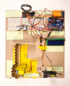
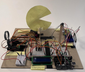
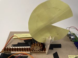
Overall project photo
Team: Sapna Tayal, Harry Ren
Our project took the input of wind speed through a wind sensor and converted that to linear motion through a rack and pinion mechanism. This linear movement is detected by an ultrasonic ranger and transmitted into an RGB value to a Neopixel-led ring.
Video of the transducers working:
Sapna:
Harry:
Sapna’s Images:
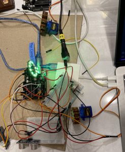
testing the light and the servo motor with a potentiometer
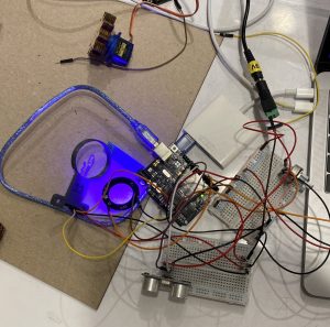
doing tests with wind sensor (the broken one so it wasn’t working)
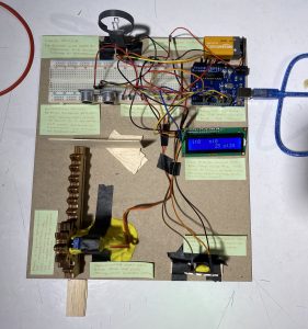
Assembly process! Adjusting the distance of the rack and pinion for an effective mapping of the ultrasonic sensor
Harry’s Images:
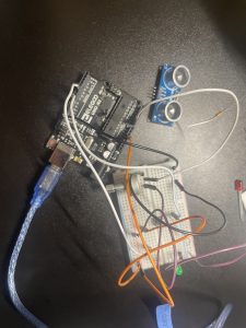
Final Transducer: Wind sensor inputs from the left, Color light outputs from the right.
Progress photo: Potentiometer LED setup which will soon be converted with a NEOPIXEL LED to test color code
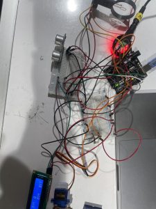
Progress photo: Completed wiring of the tranducer prior to assembly on the chip board.
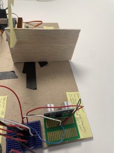
Part Highlight: ultrasonic ranger and the wall object that is being tracked. (The distance will change a light color)
Part Highlight: Servo motor driving a laser printed rack & pinion.
Discussion:
Our process for making the double transducers was one with a lot of unexpected pitfalls— often issues that weren’t really in our control. We started by ideating different transducer pairs for the middle step of the project and realizing the different strengths we brought with our differing experiences and backgrounds (Harry with more experience working with code, and Sapna with designing and building physical things), decided to go with a linear motion and ultrasonic sensor pair one that seemed exciting. Borrowing a wind sensor from Ideate lending, and playing around with example code on some neopixel led lights, we headed into what would be the horrors of putting all the pieces together. The lights and mapping of the range of the ultrasonic sensor to RGB values came first. Not finding too much help with online resources, Harry figured out a series of if statements that would cycle the RGB values from the (255, 0, 0) to (255, 255, 255) and range through the red to yellow to green to blue to purple range. Once we got that working, we focused on mapping a simple potentiometer (for testing purposes) to a servo motor that would eventually hold the gear that would eventually move the rack closer or further away to the ultrasonic sensor. This worked just fine. But the issues really started when we tried to connect the wind sensor to the motor. It was a frustrating tug of war between running the example code for the wind sensor, having it work mostly well, and then running our code to map it to the servo, and having it give up on us. The data would just be too noisy, and extremely inconsistent. Turns out it was a bunch of things out to get us: the wind sensor we were testing with was (99% sure) broken, and through reverse checking by removing big chunks of code, testing, and then adding stuff back in, we found that there was probably a library clash between the wind sensor and the neopixel precoded libraries we were using. So, with a lot of overthinking and analysing of little pieces of code, we managed to find that expanding a loop for the 12 led bulbs in the neopixel seemed to mostly solve our bugs! The last thing was fine-tuning the ranges and maps for the different pieces, adding the LCD screen and putting it all together!
With all of the electronics working, we proceeded with assembly. The process was mostly smooth. We did however, have some issues with the servo/ rack and pinion assembly. Our solution was to use modeling clay to elevate the servo to the necessary height, and use balsa strips to create a rail for the rack and pinion. After the physical assembly, we completed a final tuning of the ranges and maps for each portion. Our final product works mostly as expected and testing was limited to the consistencies of our breath as we had no other way to produce constant wind for our input.
This project served as an introduction to Arduino and electronics for the both of us and we are very happy with the final outcome. The process of successfully troubleshooting both a hardware problem, and a hidden software bug allowed us to experience both tracing physical electronic wiring and long code loops to find issues. This skill will no doubt be useful as we move on to more complex projects. Additionally, through our project and the class presentations, we learned about many useful and unique input and outputs that we could use in the future.
Arduino Code :
/*
Project Name: Double Transducer: Wind speed to Light Color

Team Members: Harry Ren, Sapna Tayal

- reads a wind speed input and converts it to a servo motor output
- reads an ultrasonic sensor input and converts it to a light color
- normalizes all input and output data and displays it on an LCD screen

Pin Mapping:
A0: Wind sensor OUT
A2: Wind sensor TMP
SDA: LCD SDA
SCL: LCD SCL
12: Ultrasonic TRIG
11: ULtrasonic ECHO
6: LED Data IN
5: Servo Data

Portions of code are adapted from the following sources
- Ideate 99-355: https://courses.ideate.cmu.edu/99-355/s2016a4/text/ex/Arduino/event-loop-programming/event-loop-programming.html
- NEOPIXEL by ADAFRUIT example: strandtest
relevant functions are credited

code by Harry Ren and Sapna Tayal at Carnegie Mellon University, (hjren@andrew.cmu.edu, sapnat@andrew.cmu.edu)
released by the authors to the public domain, Feb 2023
*/

#include <Adafruit_NeoPixel.h>
#include <Servo.h>
#include <NewPing.h>
#include <Wire.h>
#include <LiquidCrystal_I2C.h>
#ifdef __AVR__
#include <avr/power.h> // Required for 16 MHz Adafruit Trinket
#endif

// Neopixel connection Pin?
#define LED_PIN    6
// How many NeoPixels are attached to the Arduino?
#define LED_COUNT 60
// Declare our NeoPixel strip object:
Adafruit_NeoPixel strip(LED_COUNT, LED_PIN, NEO_GRB + NEO_KHZ800);

// Declare servo object
Servo doorMotor;

//Set Pin constants
const int DOORMOTORPIN = 5; //Servo Pin
const int POTPIN = A1; // Potentiometer input for testing
const int OutPin  = A0;   // wind sensor analog pin  hooked up to Wind P sensor "OUT" pin
const int TempPin = A2;   // temp sesnsor analog pin hooked up to Wind P sensor "TMP" pin
const int trigPin = 12; //ultrasonic trig pin
const int echoPin = 11; //ultrasonic echo pin
#define Max_D 20 // ultrasonic max distance

//Declare ultrasonic
NewPing sonar(trigPin,echoPin,Max_D);

//Declare LCD screen
LiquidCrystal_I2C screen(0x27, 16, 2);

//Declare Variables for Event loop programming
//Event loop function from https://courses.ideate.cmu.edu/99-355/s2016a4/text/ex/Arduino/event-loop-programming/event-loop-programming.html
long next_output_time_1 = 0;        // timestamp in microseconds for when next to update output 1
long next_output_time_2 = 0;        // timestamp in microseconds for when next to update output 2
long output_interval_1 = 250000;       // interval in microseconds between output 1 updates
long output_interval_2 = 700;       // interval in microseconds between output 2 updates
int output_state_1 = LOW;           // current state of output 1
int output_state_2 = LOW;           // current state of output 2

//setup function
void setup() {
  Serial.begin(115200);
  pinMode(POTPIN,INPUT);
  pinMode(OutPin,INPUT);
  doorMotor.attach(DOORMOTORPIN);

  strip.begin();           // INITIALIZE NeoPixel strip object (REQUIRED)
  strip.show();            // Turn OFF all pixels ASAP
  strip.setBrightness(50); // Set BRIGHTNESS to about 1/5 (max = 255)

  screen.init(); //INITIALIZE LCD Screen
  screen.backlight();
  screen.home();
  screen.clear();
}

// loop() function
void loop() {

  //Wind speed input code
  int windADunits = analogRead(OutPin);
  float windMPH =  pow((((float)windADunits - 264.0) / 85.6814), 3.36814);

  //Servo output code
  int servoval= map(windMPH,0,5,0,180);
  doorMotor.write(servoval);
  delay(100);

  //ultrasonic input code
  int ultra = sonar.ping_cm();
  Serial.println(ultra);
  int light_inp = map(ultra,12,6,0,1023);

  //set colors, no looping implemented as looping during testing resulted in library conflicts with Servo.h
  strip.setPixelColor(0, get_col(light_inp));
  strip.setPixelColor(1, get_col(light_inp));
  strip.setPixelColor(2, get_col(light_inp));
  strip.setPixelColor(3, get_col(light_inp));
  strip.setPixelColor(4, get_col(light_inp));
  strip.setPixelColor(5, get_col(light_inp));
  strip.setPixelColor(6, get_col(light_inp));
  strip.setPixelColor(7, get_col(light_inp));
  strip.setPixelColor(8, get_col(light_inp));
  strip.setPixelColor(9, get_col(light_inp));
  strip.setPixelColor(10, get_col(light_inp));
  strip.setPixelColor(11, get_col(light_inp));
  strip.setPixelColor(12, get_col(light_inp));
  strip.setPixelColor(13, get_col(light_inp));
  strip.setPixelColor(14, get_col(light_inp));
  strip.setPixelColor(15, get_col(light_inp));
  strip.setPixelColor(16, get_col(light_inp));
  strip.show();


  // https://courses.ideate.cmu.edu/99-355/s2016a4/text/ex/Arduino/event-loop-programming/event-loop-programming.html
  // read the current time in microseconds
  long now = micros();
  // Polled task 1 for output 1.  Check if the next_output_time_1 timestamp has
  // been reached; if so then update the output 1 state.
  if (now > next_output_time_1) {
    // reset the timer for the next polling point
    next_output_time_1 = now + output_interval_1;
    // toggle the output_state_1 variable
    output_state_1 = !output_state_1;

    //Screen instructions: Prints normalized values for all sensor readings
    screen.clear();
    screen.home();
    screen.print("i:");
    int normwind = map(windMPH,0,20,0,100);
    screen.print(normwind);
    screen.setCursor(6,0);
    screen.print("m:");
    int normServo = map(servoval,0,180,0,100);
    screen.print(normServo);
    screen.setCursor(8,1);
    int normultra = map(ultra,12,6,0,100);
    screen.print(normultra);
    screen.setCursor(11,1);
    screen.print("o:");
    int normlight = map(light_inp,0,1023,0,100);
    screen.print(normlight);
    }
}

// Color mapping function
//Input: int from 0 to 1023
//Output: RBG Tuple

/* RGB Values for reference
red: (255, 0, 0)
green: (0, 255, 0)
blue: (0, 0, 255)
cyan: (0, 255, 255)
purple: (255, 0, 255)
yellow: (255, 255, 0)
*/
uint32_t get_col(int i){
  //red to yellow
  if(i<170){
    i=map(i,0,170,0,255);
    return strip.Color(255,i,0);
  }
  //yellow to green
  else if (i<340){
    i=map(i,170,340,0,255);
    return strip.Color(255-i,255,0);
  }
  //green to cyan
  else if (i<510){
    i=map(i,340,510,0,255);
    return strip.Color(0,255,i);
  }
  else if (i<680){
    i=map(i,510,680,0,255);
    return strip.Color(0,255-i,255);
  }
  else if (i<850){
    i=map(i,680,850,0,255);
    return strip.Color(i,0,255);
  }
  else{
    i=map(i,850,1023,0,255);
    return strip.Color(255,i,255);
  }
}
Block Diagram and Schematics:

Block Diagram and Schematics for transducer.