Tutorial: Pan-Tilt Head
This tutorial presents the construction of a motorized pan-tilt head as an example of using the design approach of the kit. This device could be used to position a camera, mirror, gel, prop, etc. It uses two stepper motors, assumed to be driven using the grbl firmware for Arduino CNC motion as discussed in Tutorial: Stepper Motor Motion.
This tutorial has no specific deliverables, it is instead a design discussion and an opportunity to build and experiment with a a pan-tilt head. It does not use the kit parts, each element has been individually designed, but it follows a similar approach. The primary design objective has been to minimize cost by reducing component count and fabricating as many parts as possible out of plywood using a laser cutter. This design could certainly be adapted for higher precision using other materials and processes.
Contents
Pan-Tilt Parts
This structure uses the following wooden parts cut from 6 mm plywood, ordered roughly from top to bottom. This may all be downloaded from the pan-tilt DXF folder.
One additional part is cut from either felt or a slippery plastic:
The device uses the following components and hardware:
| Quantity | Component |
|---|---|
| 2 | NEMA-17 Stepper Motor, e.g. KL17H248-15-4A |
| 2 | XL timing belt, 60 tooth, 1/4 inch wide |
| 8 | M3 x 10 Socket Head Cap Screws (for motors) |
| 2 | 6mm x 20mm Shoulder Screw |
| 1 | 6mm x 14mm Shoulder Screw |
| 3 | M5 nut (for shoulder screws) |
| 3 | M5 x 10mm washer |
| 2 | M6 x 18mm washer |
| 4 | M6 x 20 Socket Head Cap Screws |
| 4 | M6 nut |
| 8 | #3 x 1/2 inch flat head wood screws (for pulleys) |
| 4 | #4 x 1 inch flat head wood screws (for base) |
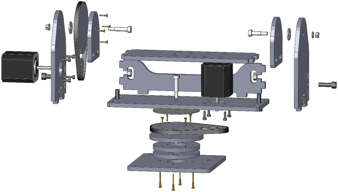
Recommended Assembly Order
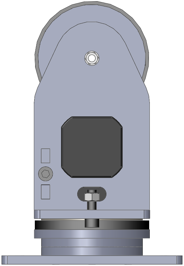
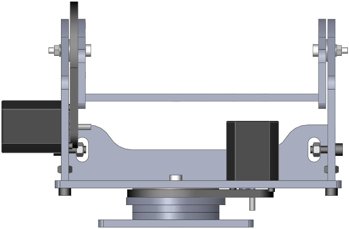
The assembly can be divided into three sections: the base, the pan axis frame, and the tilt tray.
Base. The base comprises five plates: the base, three spacers, and a large XL pulley with eight screw holes. The four long wood screws hold the bottom four elements together, and four short wood screws hold the pulley to the upper spacer. You may wish to countersink the screw holes slightly so they screws lie flush with the surface. Be careful to align the 6mm holes using a shoulder screw as a dowel.
Pan Axis Frame. The flanges and brace are assembled first, with a press fit of the tabs followed by the captive screws. This subassembly can then be attached to the pan ‘tray’ using the tabs and two more captive screws. The motors can then be attached to the tray and one flange using the M3x10 screws.
Tilt Tray. The flanges press onto the ends of the tilt tray. The large tilt pulley is screwed to one flange using four small wood screws. Be careful to align the 6mm holes using a shoulder screw as a dowel.
Lubrication. The pan axis may benefit from a light waxing of the top of the wooden pulley to reduce friction against the felt bearing surface, depending on your specific materials.
Overall Assembly. The belts should be positioned loosely before the three main elements are assembled and the shoulder screws inserted. Please note that the large washers go inside the tilt flanges, and it can take some fiddling to get these into position while the tilt axis shoulder screws are inserted.
Belt Assembly. Each pinion pulley is installed on a motor shaft using a key to press against the flat. The belts can be worked into place, the belts tensioned, then the motor screws tightened. The tilt axis can be moved to the top in order to reach the motor screws; the base has access holes for the pan motor screws.
Configuring Grbl Units
The pan-tilt head has the following drive parameters:
| motor steps | 200/rev |
| microstepping ratio | 16:1 |
| timing belt drive ratio | 48:112 |
If the desired calibration is in degrees: 200*16*(112/48)/360 = 20.741 microsteps/degree.
Assuming that pan and tilt are on the X and Y axes respectively, the following constitute reasonable grbl parameters for testing. Depending on your application, you may be able to increase the acceleration and speed substantially.
| $100=20.741 | X axis steps/degree |
| $110=2700 | X axis max rate, degree/minute |
| $120=45 | X axis acceleration, degree/sec/sec |
| $130=90 | X max travel, degrees |
| $101=20.741 | Y axis steps/degree |
| $111=2700 | Y axis max rate, degree/minute |
| $121=45 | Y axis acceleration, degree/sec/sec |
| $131=45 | Y max travel, degrees |