Description
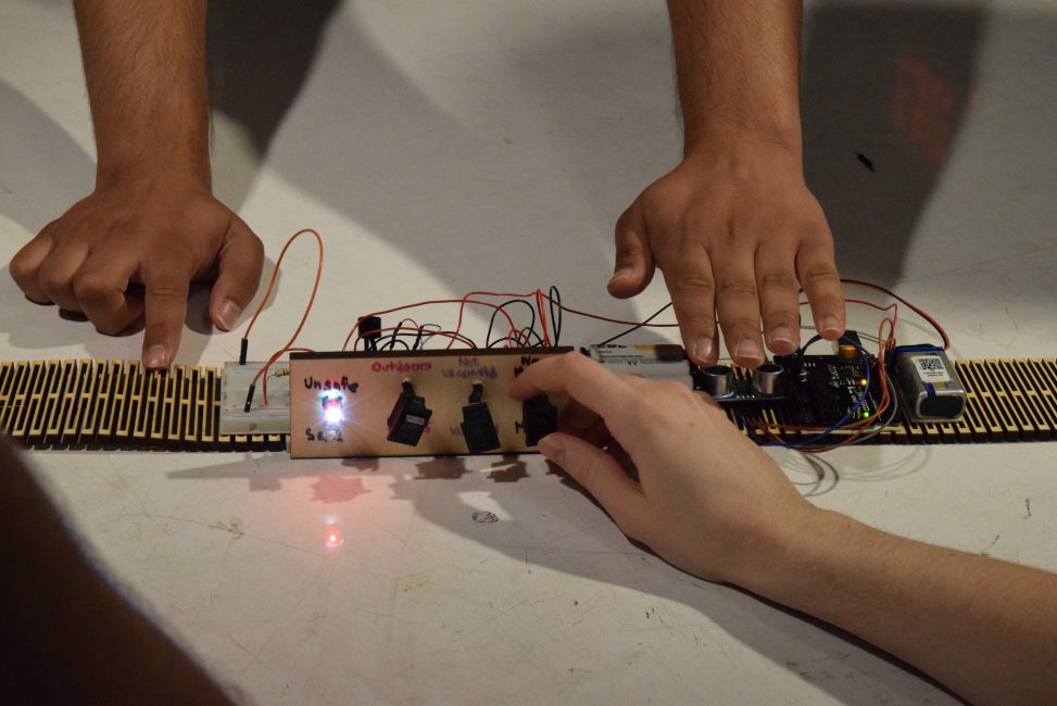
The Cov-Aid belt is a belt that helps you stay safe and battle coronavirus. It has 3 switches that help you select your statuses and 1 ultrasonic distance sensor that detects people within 6 feet in front of you. For this belt, the range is smaller than 6 feet due to limitations of the sensor. The 3 statuses are if you are masked or not, vaccinated or not, and if you are indoors or outdoors. Based on the combination of these switches and the sensor, the belt tells you if you are safe or unsafe. There are 4 outputs in total. One LED tells you if you are safe. One LED tells you if you are unsafe. The other two outputs are the buzzer and the pancake vibration motor. They work together to alert the person wearing the belt if they are inside and someone is less than 6 feet close to them. The safe LED is only on when the other outputs are off.
The belt is made up of laser-cut wood. It is cut in such a way that it can be bent and stretched. It is wide enough to hold all the components, and it is long enough to fit almost any person. The belt can be fastened by tying the connected rope.
In-Progress Media
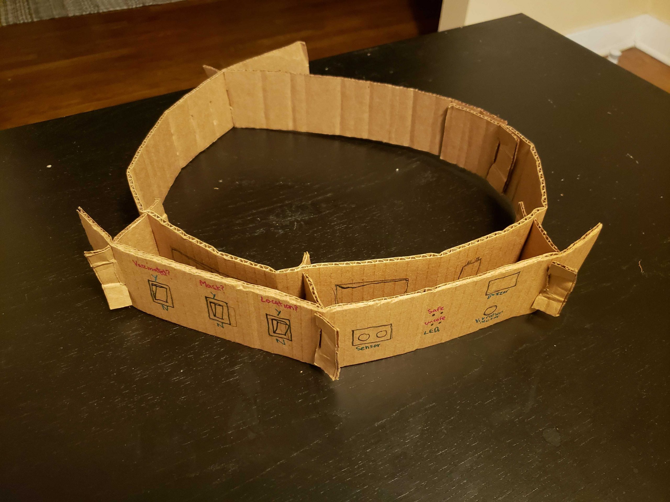
Initial model of how I wanted my belt to look like
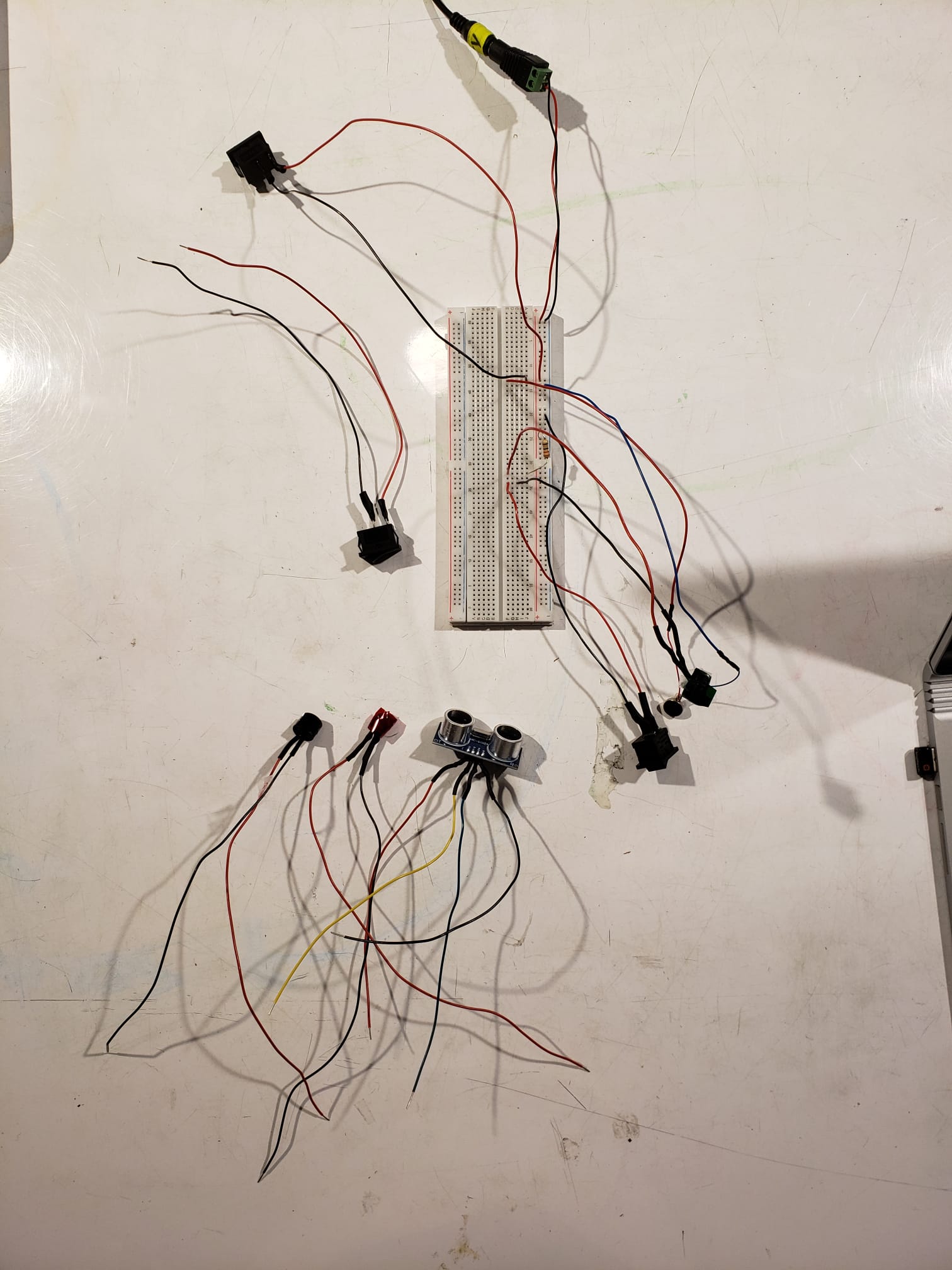
Soldering all the components so they can be used out of the breadboard
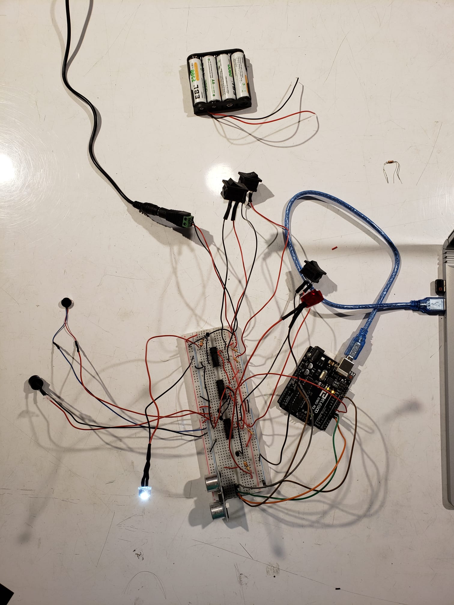
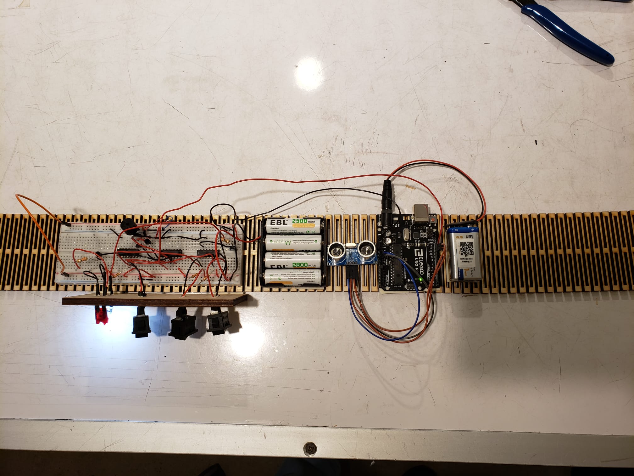
Testing the circuit with soldered components to make sure the logic is working
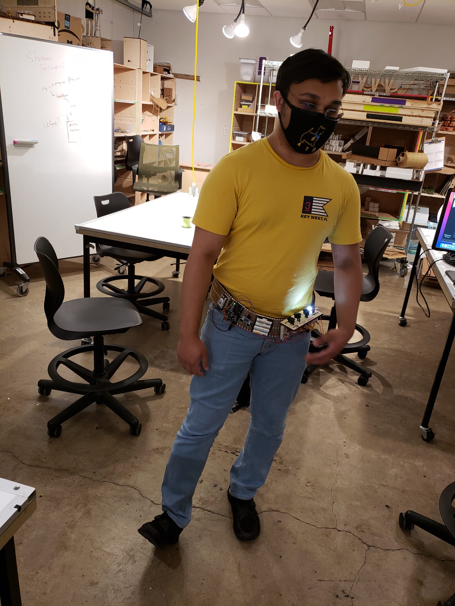
Testing components with batteries after initial mounting
Mounting everything on the belt with double sided tape and glue gun
Process Reflection
What worked well?
The flexibility of the belt seemed to have helped a lot in fastening it, as it would not only bend really well but also stretch enough to tighten around the waist. The belt was also hard at the same time allowing easy mounting of components. On top of that, bendable wood has always been a fascinating thing to me so I was glad I got to use it.
When I first tried it on, I was afraid that the components wouldn’t stay vertical. However, it seemed to be staying on pretty strong. It was even more apparent when I was trying to dismount some of the things on the belt. The reason I wasn’t too confident about it staying on was in fact not the mounting mechanism but the belt. I shall talk more about this in the next section.
Thanks to the suggestion in the in-progress critique, I made sure the switches and LEDs were facing upwards by mounting them on the board on top of the belt. This allowed the user to interact with the switches and read the LEDs properly simply by looking down.
What could have been better?
I definitely believe that the belt could have looked better. While it did give off a ‘cyborg’ vibe, the inner workings and the electronics were something I was hoping I could hide. It was an issue I ran into after mounting the components. I realized that the belt was too heavy. While the user would have been able to bear more weight, I cannot say the same about the belt. The laser-cut design that caused the belt to bend also made it weak in the vertical direction. If I added more material to hide the circuits, the middle part with the components would put too much weight resulting in either a break in the belt or a very uncomfortable and unstable belt.
The next thing I would have hoped to improve was the mounting of the components on the wooden board and how it looked. This had to be done by drilling holes instead of using the laser cutters as the laser cutters were closed on Sunday. In hindsight, I should have planned this step better to have what I needed laser cut beforehand.
Furthermore, I would have also preferred to use a different sensor with not only a larger range but also a way to detect if the object detected is a person and not a wall. This was an issue that arose at one of the earlier discussions. While it wasn’t on top of my priority list to solve this issue, I would have still preferred if I could come up with something that allowed me to differentiate an object and human being with ease.
Finally, I did gain a lot of insight into improvements I could have made in the critiques we had. Two major points were the material I could have used and another form of the kit I could have used. The first critique made me understand that I can deal with some of the weight problems I was having by using a fanny pack instead of a belt. It did seem like a good way to make it look visually better as well. The fastening mechanism would also be more secure this way. The second critique was that instead of using it like a belt, I could use it like a sash. This would definitely make it easier to deal with in terms of weight. Not only would it not feel as heavy, the weight would also be distributed horizontally.
Learning
I definitely enjoyed utilizing the maker cards with a lot of different output, input, power and control components. They helped me widen my outputs for this project, and I know that I will be using them again in the future. I am glad I was also able to implement transistors for driving components that couldn’t be driven by logic circuits. This was my first time using transistors in an IDEATE project, and I am glad I have this in my arsenal for the next upcoming projects. Lastly, the logic gates were something I was excited playing with. While I knew how they worked, I still felt like a kid trying out new toys when working with actual gate components. Learning with them made me realize how many things there are in this world that can be split into simple binary.
Pictures and Video of Cov-Aid in action

Presentation with the belt
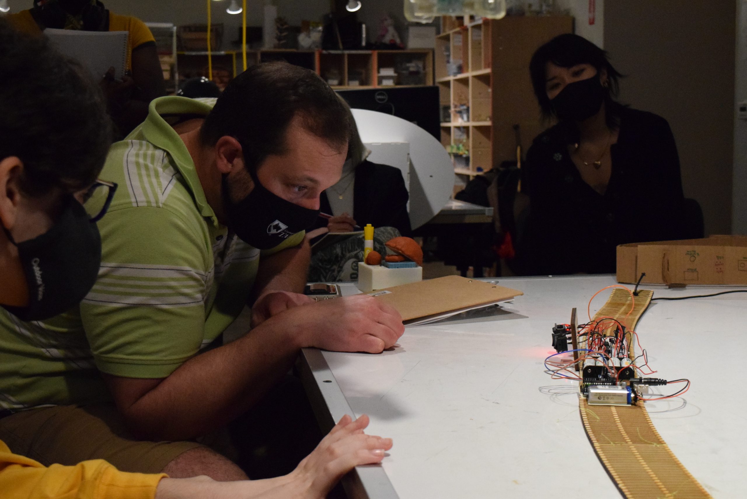
People interacting with the logic of the belt
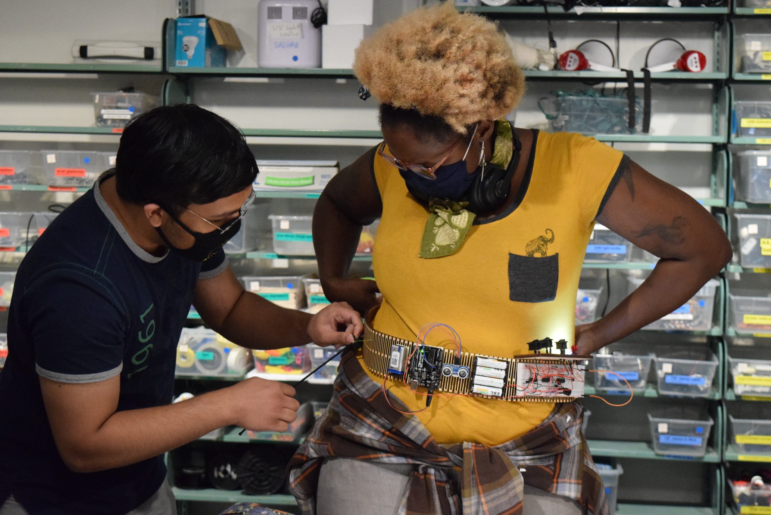
Fastening the belt on a volunteer
People testing the distance sensor and the different statuses
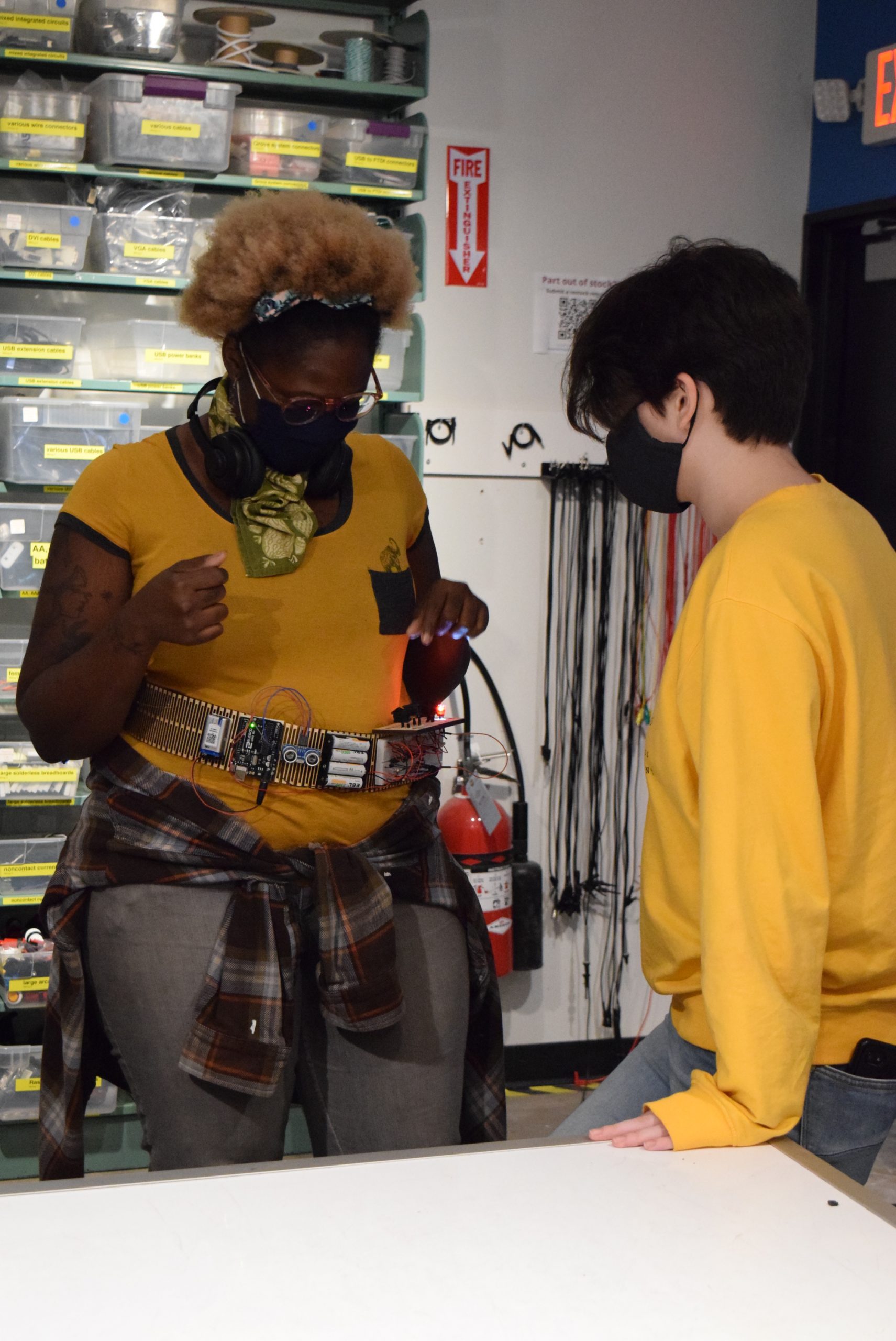
Belt on a different person to show it works on multiple waist sizes
Belt in action
Code for Ultrasonic Sensor
/*
*Cov-Aid Belt
*This code is for the ultrasonic sensor. It measures the distance of any object from the sensor
*and compares it to a threshold. If it's less than the threshold, it outputs a HIGH to SEN_PIN
*and LOW otherwise.
*/
#include <NewPing.h>

/* Part of the code taken from https://nsfsmartmakerspaces.github.io/physcomp/parts/0572/ */

const int TRIGGER_PIN = 11; // Digital output pin for chirp trigger
const int ECHO_PIN = 12;    // Digital input pin for echo reply
const int SEN_PIN = 13;
// Maximum distance we want to ping for (in centimeters).
// Typical maximum sensor distance is rated to 100cm.
const int MAX_DIST = 100;

// Variable to keep track of the current proximity
int currentDist;
int outSen;

// Setup the ultrasonic ranger with the correct pins and
// maximum distance
NewPing mySonar(TRIGGER_PIN, ECHO_PIN, MAX_DIST);

void setup() {
  pinMode(SEN_PIN, OUTPUT);
  // Setup serial port to send the current proximity back to the computer
  Serial.begin(9600);
}

void loop() {
  // Get the ultrasonic ranger distance
  currentDist = mySonar.ping_cm();
  // Send HIGH when object less than 10cm, LOW otherwise
  // currentDist == 0 implies that no object is detected
  if (currentDist<10 && currentDist!=0) {
    digitalWrite(SEN_PIN, HIGH);
    outSen = 1;
  } else {
    digitalWrite(SEN_PIN, LOW);
    outSen = 0;
  }
  // Send the data over serial
  Serial.print("Ping (cm): ");
  Serial.println(currentDist); // Send ping, get distance in cm and print result (0 = outside set distance range)
  Serial.println(outSen);
  // Delay to not send messages too fast.
  delay(100);
}