Displaying data on an I²C LCD screen
An alphanumeric LCD screen is a low-cost, simple device that makes it easy to produce a user-readable display of data. In the Physical Computing Lab, we carry “16×2” alphanumeric displays (part number 0628 in the Physical Computing Lab Inventory) which can display 16 columns of characters wide, by 2 rows tall.
Wiring
A typical 16×2 LCD screen has about 10 wires that need to be connected to the Arduino to work.
The LCD screens we carry, however, have a little “backpack” on them which does a few convenient things:
- provide a potentiometer for adjusting the screen contrast,
- allow you to switch on/off LCD screen’s backlight, and
- most significantly: condense all of the communication between the LCD screen and the Arduino into two little wires (
SDAandSCL) using the I²C communication protocol
The wiring for the LCD screen with the I²C “backpack” is very simple:
| I²C LCD pin | Arduino pin |
|---|---|
SDA |
SDA (close to the reset button, to the right of pin 13) |
SCL |
SCL (right next to SDA) |
VCC |
5V |
GND |
GND |
Writing to the screen
This tutorial uses the Arduino library called “LiquidCrystal I2C” by Frank de Brabender, based on work from DFRobot. As of this writing (November 2018) this library works nicely with the Phys Comp Lab’s I²C LCD screens. If you don’t have this library, in the Arduino IDE (development software), select Tools –> Manage Libraries… and search for LiquidCrystal I2C. Select this library and click Install.
Here’s a sketch that will display sample text and show you how to use various features of the library:
/*
Example showing how to use the LiquidCrystal_I2C library.
Demonstrates:
- initializing an LCD device
- setting the cursor
- printing text
- turning the text display on and off
- turning the backlight on and off
- printing right-justified text
- printing a variable's value
- scrolling text laterally
- using special characters
- using characters you define yourself
- modifying only one part of the display
Below is a diagrammatic map of each cursor position in a 16 x 2 (columns x rows) display.
Each position is notated as a (column,row) coordinate.
(0,0) (1,0) (2,0) ... (15,0)
(0,1) (1,1) (2,1) ... (15,1)
example code by Robert Zacharias at Carnegie Mellon University, rzach@cmu.edu
released by the author to the public domain, November 2018
*/
#include <Wire.h>
#include <LiquidCrystal_I2C.h>
/* Create an LCD display object called "screen" with I2C address 0x27
which is 16 columns wide and 2 rows tall. You can use any name you'd like. */
LiquidCrystal_I2C screen(0x27, 16, 2);
int x = 123;
/* Definition of a custom character called "frowny" which will be used later.
Each digit is a pixel of the 5x7 array that forms a single character on this display.
Draw your own at https://maxpromer.github.io/LCD-Character-Creator/ */
byte frowny[] = {
B00000,
B11011,
B11011,
B00000,
B00000,
B01110,
B10001,
B00000
}; // (note the extra row of zeros at the bottom)
void setup() {
// initialize the screen (only need to do this once)
screen.init();
// turn on the backlight to start
screen.backlight();
// set cursor to home position, i.e. the upper left corner
screen.home();
// print the words Hello, world! onto the screen starting at the above cursor position
screen.print("Hello, world!");
// move cursor to column 0, row 1
screen.setCursor(0, 1);
// print text starting in that position
screen.print("2nd row text");
delay(2000); // do nothing for 2 seconds
// noDisplay() and display() will switch off and on the text
screen.noDisplay();
delay(1000);
screen.display();
delay(1000);
// noBacklight() and backlight() will switch off and on the backlight
screen.noBacklight();
delay(1000);
screen.backlight();
delay(1000);
screen.clear();
// autoscroll() will make the text right-justified, noAutoscroll() is regular flow
screen.autoscroll();
// therefore, set the cursor one square off of right side of the screen
screen.setCursor(16, 0);
screen.print("righttext");
delay(1000);
screen.noAutoscroll();
screen.clear();
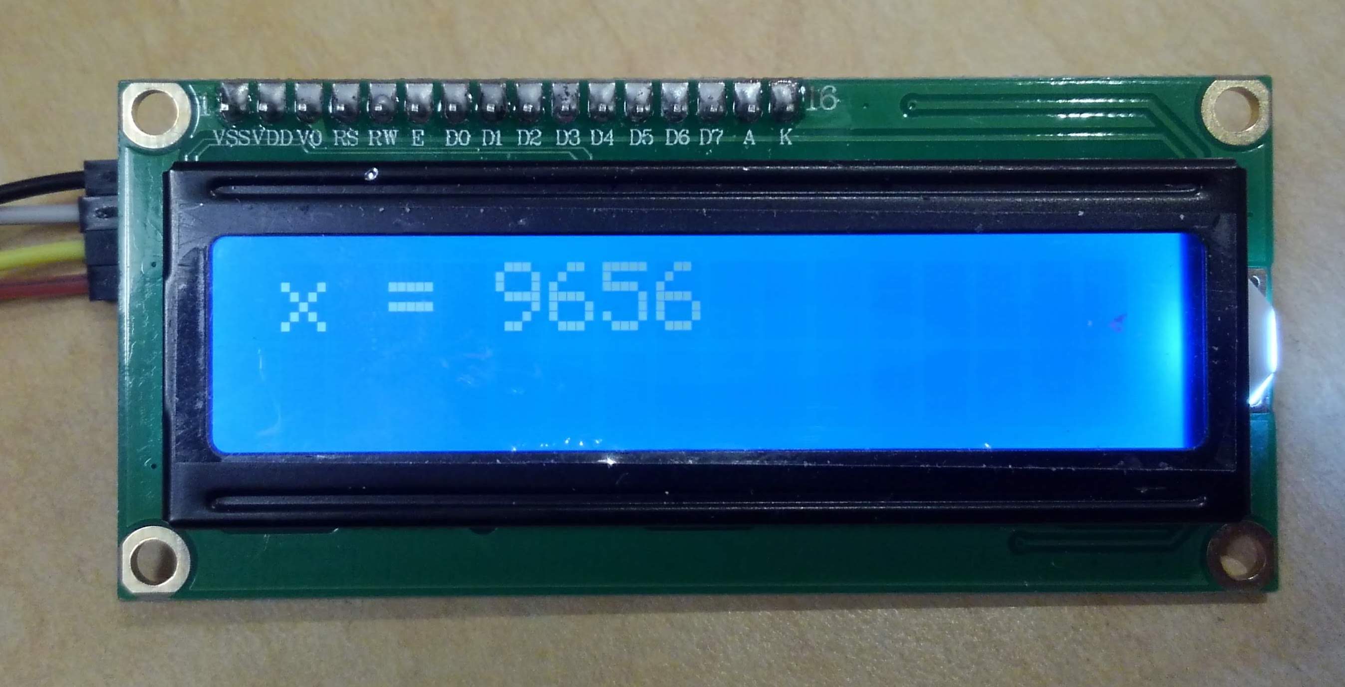
// you can also display a variable on the screen
screen.home();
screen.print("x = ");
screen.print(x);
delay(1000);
screen.clear();
/* You can scroll the display right or left to show long text lines, etc.
Use screen.scrollDisplayLeft() and ...Right() to move in one-column increments. */
screen.home();
screen.print("top long line of text, too much!");
screen.setCursor(0, 1);
screen.print("a second line that's also too long");
for (int i = 0; i < 25; i++) {
delay(500);
screen.scrollDisplayLeft();
}
screen.clear();
/* You can create custom characters.
screen.createChar() below reads the array "frowny" (defined above)
and loads it into memory location 0 on the LCD screen. */
screen.createChar(0, frowny);
/* Use screen.write(codenumber) to print pre-defined non-standard characters.
See https://learn.robotgeek.com/getting-started/59-lcd-special-characters.html
for a complete table of available symbols and their codes. */
screen.home();
screen.write(126); // right arrow symbol
screen.print(" ");
screen.write(243); // infinity symbol
screen.print(" and beyond!");
screen.write(233); // to the negative first power symbol
screen.setCursor(0, 1);
screen.write(232); // square root symbol
screen.print("(-1) = ");
screen.write(0); // "0" is the memory address of the custom character "frowny" from above
delay(5000);
screen.clear();
screen.home();
screen.print("x = ");
}
void loop() {
// just count up to show x changing (the rest of the text will remain untouched)
screen.setCursor(4, 0);
screen.print(x);
x++;
delay(1000);
}
I don’t see anything!
If you’ve wired the screen as mentioned above but aren’t seeing text, there are some easy troubleshooting steps:
1. The contrast potentiometer may be set incorrectly
There is a blue rectangular box on the back of the I²C backpack with a cross inscribed into a grey circle. This is a potentiometer, adjustable with a small screwdriver.
While looking at the front of the LCD screen, slowly turn this potentiometer to make the characters appear properly.
2. The I²C address may be set incorrectly
If you’re seeing a row of blocks on the screen, or no text at all, you may have the wrong I²C address set.
Line 32 of the example sketch given above is:
LiquidCrystal_I2C screen(0x27, 16, 2);
The 0x27 in that line represents the I²C address of the LCD screen—however, if that address is incorrect, then your Arduino won’t send signals to the screen.
First: try the alternative address 0x3F in that line of code; some of our I²C LCD screens have that address instead of 0x27 but they don’t look any different physically.
If it still isn’t working then upload the following “I²C scanner” sketch to your Arduino and open up the Serial Monitor. You should see serial feedback indicating the I²C address of all devices attached to the Arduino, including your LCD screen. Use that value in the address field in line 32 of the example sketch.
/*
  i2c_scanner

  Version 1
    This program (or code that looks like it) can be found in many places.
    For example on the Arduino.cc forum. The original author is not know.
  Version 2, Juni 2012, Using Arduino 1.0.1
     Adapted to be as simple as possible by Arduino.cc user Krodal
  Version 3, Feb 26  2013
    V3 by louarnold
  Version 4, March 3, 2013, Using Arduino 1.0.3
    by Arduino.cc user Krodal.
    Changes by louarnold removed. Scanning addresses changed from 0...127 to 1...119,
    according to the i2c scanner by Nick Gammon http://www.gammon.com.au/forum/?id=10896
  Version 5, March 28, 2013
    As version 4, but address scans now to 127. A sensor seems to use address 120.
  Version 6, November 27, 2015.
    Added waiting for the Leonardo serial communication.

  This sketch tests the standard 7-bit addresses
  Devices with higher bit address might not be seen properly.
*/


#include <Wire.h>


void setup(){
  Wire.begin();
  Serial.begin(9600);
  Serial.println("\nI2C Scanner");
}


void loop() {
  byte error, address;
  int nDevices;

  Serial.println("Scanning...");

  nDevices = 0;
  for (address = 1; address < 127; address++ )
  {
    // The i2c_scanner uses the return value of
    // the Write.endTransmisstion to see if
    // a device did acknowledge to the address.
    Wire.beginTransmission(address);
    error = Wire.endTransmission();

    if (error == 0)
    {
      Serial.print("I2C device found at address 0x");
      if (address < 16)
        Serial.print("0");
      Serial.print(address, HEX);
      Serial.println("  !");

      nDevices++;
    }
    else if (error == 4)
    {
      Serial.print("Unknown error at address 0x");
      if (address < 16)
        Serial.print("0");
      Serial.println(address, HEX);
    }
  }
  if (nDevices == 0)
    Serial.println("No I2C devices found\n");
  else
    Serial.println("done\n");

  delay(5000);           // wait 5 seconds for next scan
}
3. The jumper to power the backlight LED may be missing
There are two male pins sticking out of the left side of the I²C backpack labeled “LED.” If they are in electrical contact with each other, then the backlight will illuminate when screen.backlight() is called, and you’ll be able to read the words on the LCD screen. But if they are not in electrical contact, the screen backlight will never light up.
Use a small “jumper” to easily connect these pins to each other if they’re not already connected. In Phys Comp, we have jumpers: part 0726 in bin 2, row 4, column 5.
