Using a ULN2803 transistor
The transistor’s job is to act as a switch; the Arduino doesn’t need to touch the 6V external power supply shown in this circuit, but can just flip the “switch” on pin 5 to affect the motor on the left, or pin 8 to affect the motor on the right.
This circuit uses a ULN2803 transistor, which is actually a single IC (chip) with 8 different transistors in it.
A digital HIGH signal from the Arduino will turn the motor on, and a LOW signal will turn it off. Notice that the motors are always connected to power (they are plugged right into the 6V supply), so what the transistor does in this case is “turn on and off” their connection to ground. It’s a funny logic, but it works!
The circuit
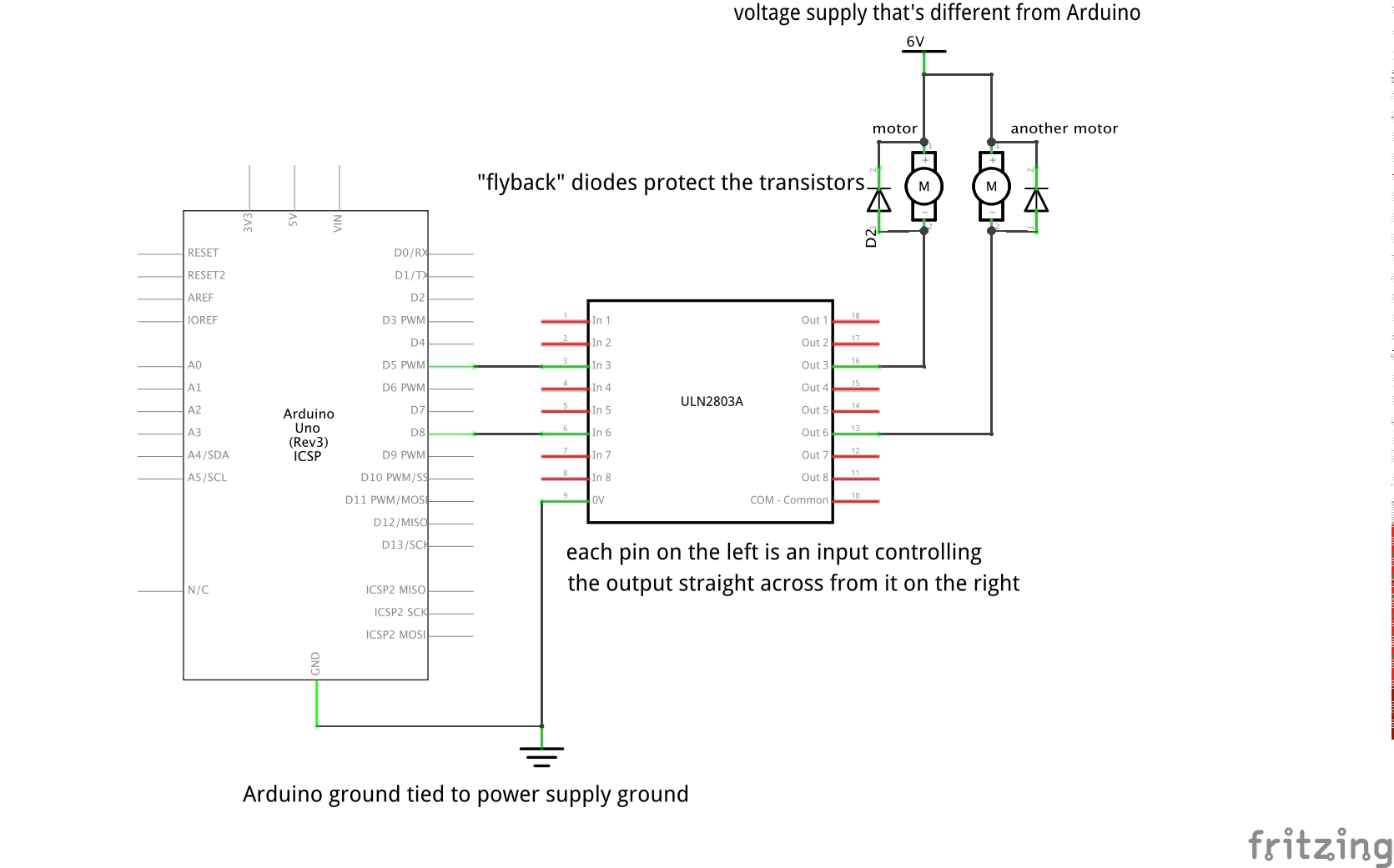
The diodes attached parallel to the motors are there for the protection of the transistors. They are necessary because when power is suddenly shut off to a coil (motors have big coils in them), that coil has a tendency to kick with a high voltage for a brief period. The diodes give that kick somewhere to go so it doesn’t damage anything. You don’t need diodes like these if you’re powering something without a coil, such as an LED strip.
Sample code to drive the motors
Sample Arduino sketch to play with switching two loads on and off:
const int MOTOR_ONE = 8; // shortcut to refer to the motor pin later
const int MOTOR_TWO = 5;

void setup() {
  pinMode(MOTOR_ONE, OUTPUT); // we will be writing data to the motor pins
  pinMode(MOTOR_TWO, OUTPUT);
}

void loop() {
  // we can “blink” pin 8 (MOTOR_ONE) by just turning it on for a bit
  digitalWrite(MOTOR_ONE, HIGH);
  delay(500);
  digitalWrite(MOTOR_ONE, LOW);


  // we can also fade pin 5 (MOTOR_TWO) up and down, because it’s a PWM (tilde)
  // pin so it can do analog write in addition to digital write

  // fade from 0 to 255, which is the full range of analogWrite
  for (int i = 0; i < 256; i++) {
    analogWrite(MOTOR_TWO, i);
    delay(5);
  }

  // fade back down from 255 to 0
  for (int i = 255; i > 0; i--) {
    analogWrite(MOTOR_TWO, i);
    delay(5);
  }
}
