Exercise: Juggling System Design
The main objective of this exercise is to explore kinematic and dynamic principles through the design and simulation of a simple juggling system. For the purpose of this exercise we will define ‘juggler’ as a machine which can keep one or more passive objects in continuous motion. The emphasis is on designing a kinetic sculpture as an articulated structure of rigid bodies connected by joints. It will move under the combined influence of gravity, physics, and actuators. Every juggler involves free object motion and is intrinsically underactuated.
A fully actuated system is one in which every degree of freedom is controlled. For example, a typical industrial robot arm has six joints, each with an servomotor actuator with position control. Within the workspace the end effector has six degrees of freedom and the pose is fully controlled. Such system frequently manipulate parts by gripping the part to rigidly connect the object kinematics to the robot.
In contrast, an underactuated system has degrees of freedom which cannot be directly controlled. Our specific interest is in systems with more degrees of freedom than actuators, resulting in one or more passive freedoms. We utilize this kind of dynamics constantly, e.g. when pushing an object across a table using one fingertip, the point contact has only two freedoms but the object has three planar freedoms, and we use our experience of friction and dynamic control to stabilize the action.
In some sense, every robotic system is underactuated. At the core, the very notion of rigid body system is an abstraction which omits freedoms. But also in practice, robots which are mobile or which manipulate objects come into contact with a great many external freedoms which may transiently become part of the robot system. E.g. a mobile robot might need to open a door, or push around objects, or grasp a flexible or articulated object.
As a creative practice, passive freedoms add dynamic kinetic possibilities to a machine in a parsimonious way. Consider the use of clothing and hair in animation: the core expressive movements of the body are amplified through the motion of the attached soft materials.
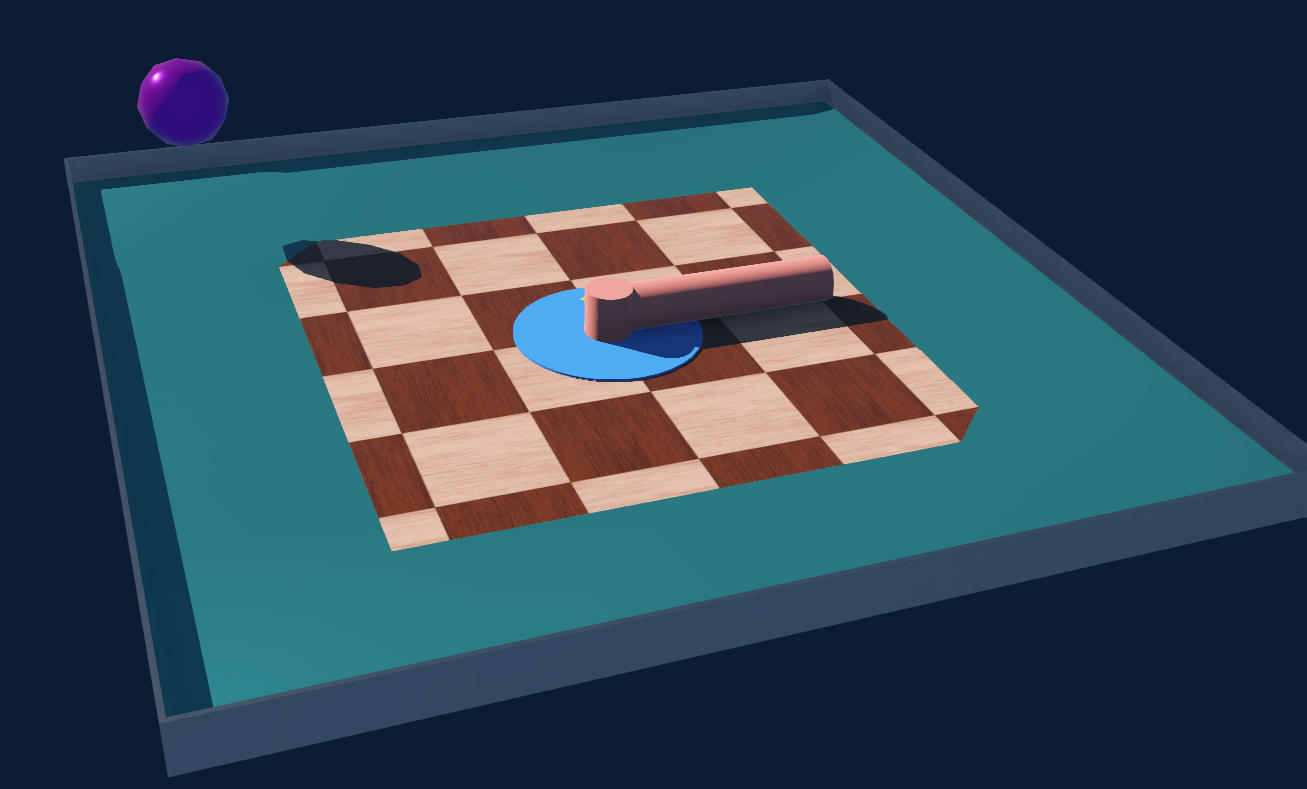
Screenshot of sample Webots model of the impeller in an arena with a sloped ElevationGrid floor providing a central restoring force.
Contents
Objectives
After this exercise, you should be able to:
Design a kinetic sculptural form using rigid bodies and joints.
Manipulate and extend a kinematic description of a rigid body system.
Attach actuators to simulated joints.
Manipulate dynamic properties of a rigid body system, including mass and friction.
Reference Guides
Please review the following reference guides as needed:
Documentation on the sample project: Impeller Robot Model
Resources
The sample Webots world is included in the reference project Webots.zip described under Webots Robot Simulator Examples.
The sample model is documented in Impeller Robot Model.
Webots/worlds/impeller-demo.wbt: sample world file, opening it should launch the simulatorWebots/controllers/impeller/impeller.py: Python script to control the simulated robot
Creative Constraints
TBD
Creative Possibilities
You may choose either a vertical or horizontal juggling cycle.
You may wish to add additional tilted or shaped ground bodies or obstacles as ‘passive’ manipulators.
The impeller robot can be duplicated and modified. As long as the motor name remains the same different version can share the same controller.
General Recommendations
Stick with hinge joints (pivots) to start; other joint types can come later (e.g. linear sliding joints).
Choose a convenient ‘reference pose’ in which all joints are at a neutral position. The work will be simpler if this is as axis-aligned as possible.
The Webots native units are meters. Shape objects can be scaled but it is simplest to design in meters.
Start with careful paper sketches, including a careful kinematic diagram with the joint axes and body coordinate systems.
Build and test a model incrementally. It is much easier to fix coordinate systems and parameter vectors in stages.
Use basic geometric forms to work out the kinematics, dynamics, and contact models. The visual shape and rendering properties can be detailed later if desired.
Parameters can be adjusted while the simulator is running. But I highly recommend you get in the habit of resetting the simulation state before saving any world changes in order to preserve the accuracy of the initial conditions.
A physical structure with rich dynamics may not need much motion programming, as even simple actuation processes might activate the system by exciting the dynamics. E.g. the sample controller code just applies a periodic movement via the motor. This could be elaborated by coupling the movement to the sensor to respond to proximal objects.
Deliverables
Please submit to Canvas:
A paragraph briefly describing your sculptural objectives and outcomes.
Short video clip (under one minute) of simulated behavior, submitted to Canvas either as a video file or a link to a third-party streaming service.
Zip file of your Webots project.