Project Objective
Our objective was to replicate microfluidics experiments from the paper ‘Venous Materials’ at a larger, more wearable scale, by using molds, silicone, and traditional bonding techniques. We wanted to explore various aesthetic effects of moving liquid from a silicone repository through a set of channels, where the motion would be actuated by physically pressing on the channel. We also wanted to explore reversible color change, caused by different colors of liquid traveling through separate but overlapping channels. Additionally, we wanted to explore how we could design our silicone microfluidics piece such that liquid could get locked into a specific area, even when pressure was released from the repository.
Creative Design Opportunities
When we first began this project, we had initially planned to create a silicone piece for athletes to wear that uses microfluidics to visually indicate pressure applied to different parts of the body. For example, a headgear could have a liquid repository that, when pressed (after the side of the head was banged), would release liquid through a channel into a “locked state”. We wanted this effect to be reversible; we were aiming to design our silicone piece so that applying pressure at various points could cause the liquid to retreat back from its locked position into its original repository.
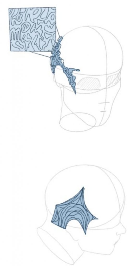
Above all, we were aiming for a strong visual component to our silicone piece. We wanted our liquid to flow through channels in an intricate, beautiful way, and incorporate effects such as color change. In short, we wanted our piece to not only be functional, but also aesthetically pleasing and invoke a ‘surprise effect’ when the liquid traveled through the channels upon impact.
We also realized that because we wanted this piece to be wearable, the individual layers making up the full piece needed to be as thin as possible, so that when we stacked them, the overall piece would be flexible and allow free motion of the body.
Outcomes
At first, we decided to use Ecoflex 45 for our experiments. We started by testing simple motion of liquid through a short channel, which was successful. We did this with two layers: one which was a piece of silicone that contained deformations for the repositories and channel with a floor underneath, and the other was a piece of silicone that served as the ‘ceiling’ to this first piece. We bonded the two pieces and injected liquid from the top of each repository using a .5 mm needle.
We then moved on to testing an overlap effect by essentially creating two of the first piece we tested, and bonding them on top of each other. We injected blue liquid into one side and red liquid into the other, with the blue liquid accidentally being much lighter than the red liquid, seeing as we didn’t realize how volume of colored liquid impacted how dark the liquid was. Thus, we could see that on the side with the red liquid, the liquid going through the channel appeared bright red, however on the side with the blue liquid, we saw that the liquid appeared purple because of the red directly underneath. In the video, we can see the actual blue color in the square repository, where the red isn’t overlapping. Thus, our overlap effect was successful.
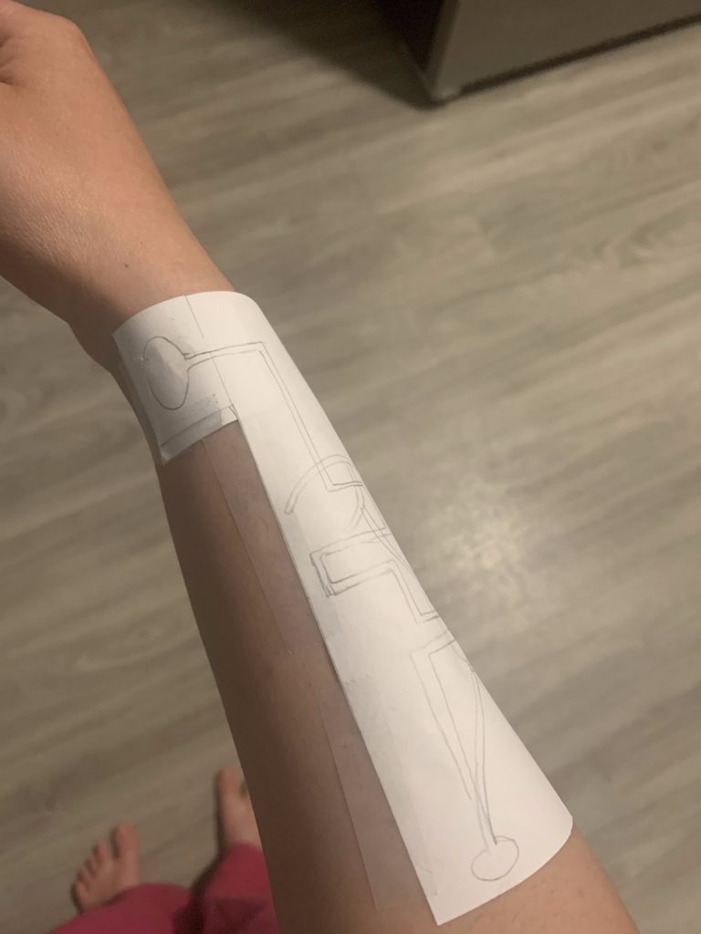
Afterwards, we tried to scale up our design into a full wearable piece with simple actuation: press the liquid repository in the palm and liquid would travel up to the fingertip. However, when scaling up, we realized that when we were making the liquid repository and channel bigger, we also had to adjust the thickness of the silicone accordingly, otherwise pressure wouldn’t be concentrated in such a way as to make the liquid move.
Next, we experimented with a locking mechanism. We wanted to imitate the mechanism from ‘Venous Materials’ here:
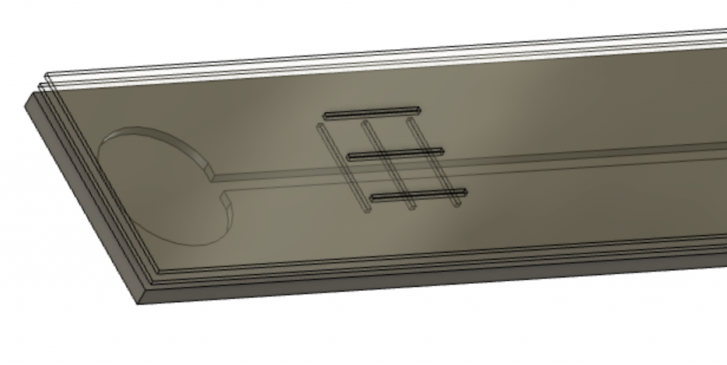
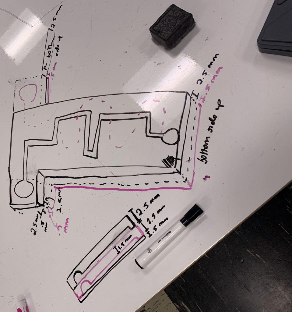
After viewing this effect several times, and prototyping with paper, we decided we needed four layers to imitate this effect. The first layer would be the standard “repo + channel” layer, with deformations for both and a floor underneath. The second layer would be a .5mm sheet of silicone with 3 vertical grid line punctures that were 15mm long and 2mm thick, the third layer would be a .5mm sheet of silicone with 3 horizontal grid line punctures that were 15mm long and 2mm thick, and the fourth would be the ‘ceiling’ layer. Liquid would travel from the repository through the channel in the base layer, then flow through the vertical punctures in the second layer and travel along the ‘floor’ of the third layer surrounded by the walls of the horizontal punctures. Surface tension, we hoped, would keep some of the liquid trapped in the third layer, with the rest of the liquid flowing from the third to the first layer. After discovering that 2mm thick grid lines were too thick to enable much surface for the liquid to bond to, we settled on .5mm thick grid lines.
Since this required some very fine bonding and detail work with the molds, we initially experimented with laser cut .5mm Yupo paper layers for the grid layers. This ended up working poorly because the Yupo paper bonded very badly to the silicone top and bottom layers, which meant liquid would consistently leak out of the ends. Additionally, it was a bad idea to inject into the repository from the top because upon pressing the repository, liquid would gush out through the injection hole.
Although we ended up getting an effect similar to what we wanted, as shown below, it was dubious as to whether this was because the Yupo paper was getting stained, or the liquid was actually getting trapped. Thus, we moved on to actually using silicone for all 4 layers.
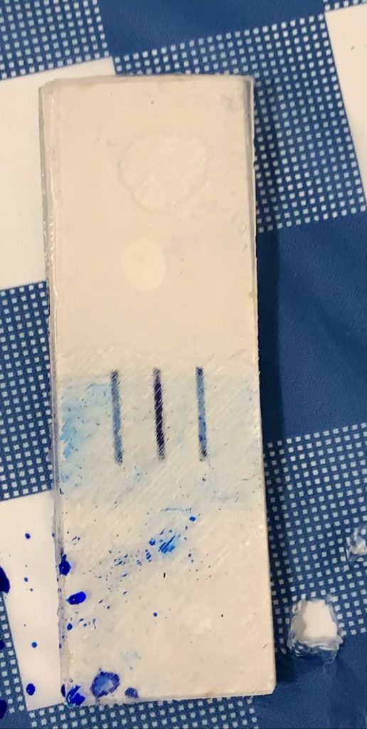
When we used silicone for all 4 layers, we ran into a lot of issues related to bonding, where liquid would easily leak from the channel/grid lines out of the sides. Our first semi-successful attempt involved the use of DragonSkin 20, hence why we decided to make the switch to DragonSkin after using EcoFlex 45 for all of our previous attempts. This we considered successful because as intended, liquid was traveling orthogonally to the initial direction of the base channel, and then it was getting trapped in the third layer due to surface tension (note the dark blue stain among the lighter blue). However, the effect wasn’t that pronounced, so it wasn’t a complete success.
From this, however, we learned that we could devise a mechanism where liquid would travel from a channel in the base layer through a puncture in the layer above it into a second channel in that same layer (include an image to illustrate what you’re talking about). This meant that we could potentially achieve the color overlap effect without the traditional approach of channel + ceiling + channel + ceiling, instead doing channel + channel + ceiling, which meant that our overall silicone piece could be much thinner.
When we put this into practice, however, our results were poor because it proved difficult to bond the layers together. There was the pitfall of using too much silicone to bond, and having the second layer channel be sealed up with silicone, or using too little silicone to bond, and having liquid from the base layer mix with the liquid that was in the second layer, because there wasn’t enough silicone to bond the part of the sheet that separated the base layer and second layer, or having the liquid leak out from the sides where the puncture was located.
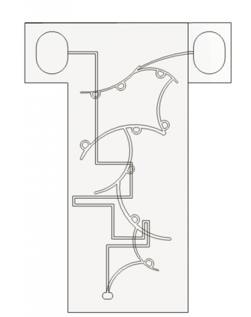
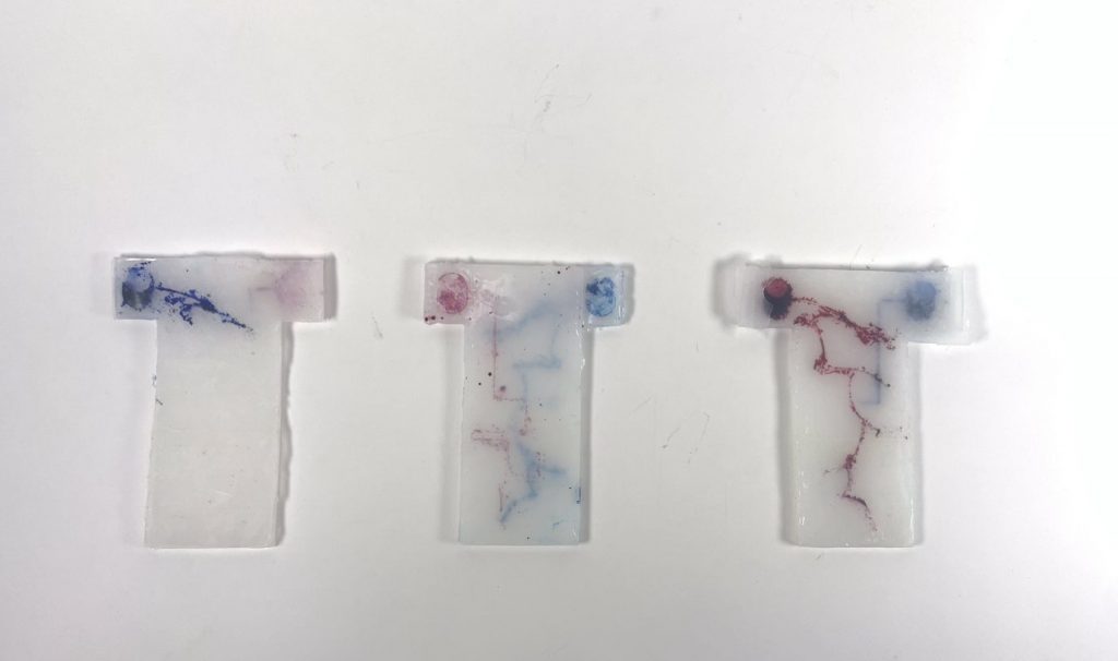
Our final experiment involved a small tweak to the first approach where we stacked channels on top of each other. Instead of doing channel + ceiling + channel + ceiling, where each “channel” piece would be face-up with the floor on the bottom, we decided to do ceiling + channel A (face down) + channel B (face down), where the floor of channel A would serve as the “ceiling” of channel B. In order to reduce the likelihood of liquid colors mixing, which was still possible if the liquid repositories were stacked directly on top of each other and a needle accidentally punctured the floor of the topmost repository, we also decided to design the layers in a “wristwatch” style. This meant that one repository was located on the left side of the wrist, and the other repository was located on the right side of the wrist, so if the needle accidentally punctured the floor of either repository, there was no way for color to mix between the two.
This method turned out to be our most successful method, though we still had a lot of issues with bonding. The way we solved this was by using a paintbrush to apply an even layer of silicone. Additionally, the Dragonskin 20 turned out to be too opaque to clearly see the different colors of liquid when layers were stacked, so we reverted back to using Ecoflex 45. We discovered our issues with Ecoflex 45 in the past had been due to poor bonding and poor injection.
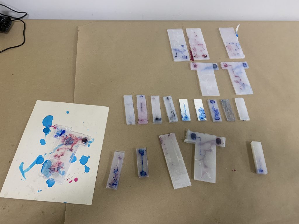
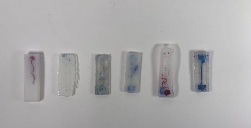
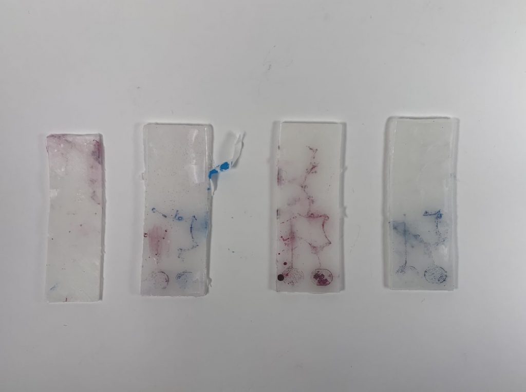
Here are our most successful experiments
Key Takeaways
For injection
- Before injecting, turn the needle upwards, tap on the side of the liquid chamber a few times, and slowly push up to release any air. This won’t release all of the air, but it will release most of it, and keep the repository from ballooning up when injected with the needle
- Inject from the back side of the repository and slowly shimmy the needle into the actual repository before releasing liquid. Additionally, don’t inject too close to the repository’s ceiling, but also don’t inject too close to the floor. Otherwise, it’s easier for liquid to leak out after injection
For molding
- When making molds with a certain depth for the channel, make sure that there’s a decent amount of thickness for the floor. Ie if your mold has 2mm deep channels, the floor underneath those channels should be at least 5mm, meaning the entire mold should be 7mm tall. Otherwise, the printer won’t register the floor as existing.
- Use the vacuum degasser to remove air bubbles
For channel/repo design
- Channel volume (area * depth) should be less than or equal to the volume of the repository
- If you’re scaling up the area of your repository (i.e. by 1.5x), you need to scale up the depth of the repository (i.e. by the same 1.5x)
For bonding
- Use a paintbrush to get an even layer
- Potentially create a slightly raised silicone “wall” around your channel in the base layer that combines with indents in the ceiling layer, so that when bonding, you don’t need to worry about silicone leaking into the actual channel and can thus be more generous with applying the bonding layers
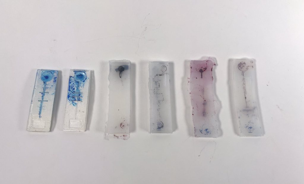
Overall, a lot of mistakes were made, and a lot of trials were needed. Here are the trials we did.
How the Molds were fabricated
In Fusion:
- We started by modeling what we wanted the silicone piece to look like
- If the silicone piece had divots for the channels, we would flip it 180 degrees so it was upside down
- We then made a larger block that surrounded the piece and had its ceiling level with the ceiling of the silicone piece (or flipped piece), and had a height that was ~5mm additional to the height of the silicone piece
- We then used “Combine”, used the larger block as a Target body and the silicone piece as the Tool body, and used the cut operation, keeping the tool for volume calculation purposes
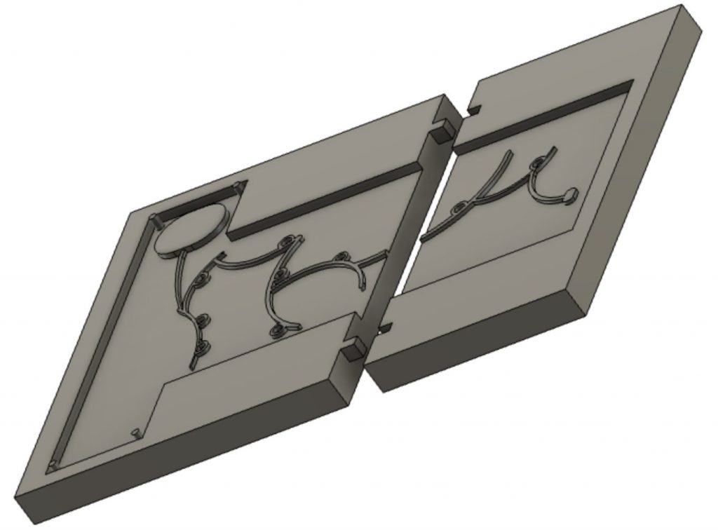
In order to have multiple molds combine to create one silicone piece (in the event that the printer can’t handle the entire mold), we would slice the mold at a particular space (preferably where there wasn’t a lot of intricate channel work happening) and then create hinges so the two edges of the ‘broken’ mold can connect into one.
Technical and Artistic Contributions
Sunjana
- Engineered and cadded up molds for grid locking mechanism
- Engineered and cadded up all large-scale molds (puncture overlap, wristwatch, initial single-channel with palm repository)
- Engineered and cadded up small molds for initial pressure and color change tests
- Constructed and bonded all silicone pieces for grid locking tests, initial pressure tests, and color change tests
Jina
- Designed the look of the channels and how they would overlap
- Engineered and cadded up small molds for overlap using final channel design
- Engineered and cadded up molds to test shape change due to pumping air
- Engineered and cadded up molds to test Tesla locking valve
Sunjana and Jina worked together on bonding the molds for the puncture overlap mechanism, the wristwatch overlap mechanism, and the smaller version of the wristwatch overlap mechanism (channel + channel + ceiling). Sunjana primarily worked on molding and injecting while Jina worked on bonding. They also worked closely together on ideation.
Final Documentation of Prototypes
When we first started working on our project, we tested simple mechanisms through different techniques like using paper to even just having an extra layer in between. In regards to the paper, the material would stain and not be affective.
https://youtube.com/shorts/uTZhcKelyHE?feature=share
https://youtube.com/shorts/xj96ZMnt1KQ?feature=share
In the video above, you can see the earlier iterations that we created. Due to the video uploading as a short (it can not embed into wordpress). We tried to upload as a normal video but it wouldn’t let us.
In the final prototype, we tried to perfect the bonding as it would affect how the patterns would appear.
https://youtube.com/shorts/YuYRkwfu4b0?feature=share
https://youtube.com/shorts/av7hcFXaE_A?feature=share
Citations
Hila Mor, Tianyu Yu, Ken Nakagaki, Benjamin Harvey Miller, Yichen Jia, and Hiroshi Ishii. 2020. Venous Materials: Towards Interactive Fluidic Mechanisms. In CHI Conference on Human Factors in Computing Systems (CHI ’20), April 25–30, 2020, Honolulu, HI, USA. ACM, New York, NY, USA 15 Pages. https://doi.org/10.1145/3313831.3376129