The interaction installation is composed of plants that react to gentle contact by producing a computer-synthesized sound. The texture and volume of the sound depends on movements and gestures made by the person.
Taiko no Tatsujin
This is a arcade/video game that based on music and rhyme. Players can recognize if they are doing a good job by listening to the rhyme of the music, the rhyme made by the drum, and feedback lines like “50 strikes”.
Augmented Drilling Machine
The device makes pulsing sound of different pitches if the drill is deviated from the ideal angle to different angles.
After reading Make it So Chapters 6 and 10, I have realized that sound has many more roles than I thought. To people, sound can provide clues of the size of the space, direction, or even the distance. It is far more capable of being used as an alert/alarm. The sound is one of the strongest elements to involve in a device. It does not only interacts with people physically but also psychologically. Sound is a valuable part of human memory. This means, that in a device, one can even approach to condition one to the sound of the device. For example, when we hear our phone ding, the thumb is already tapping the screen for thumbprint recognition/password. The power of sound can also be seen in emotional interaction. For example, music can make one feel the whole spectrum of emotions such as being gloomy or calm. This can be used in devices that cooperate for one’s emotional support in situations like when one indicates physical signs of being angry such as faster heartbeat/increase in blood pressure, the device can detect those signs and play calm music. Sound can also interact with the user from sound to sound — like a conversation. As Chapter 10 mentions, features like playback can also play a big role in devices even if the sounds don’t necessarily make a full-on conversation (even siri today fails to make a smooth conversation!) Sound gives people a lot of space to work with, and the fact that sound doesn’t necessarily have to be audible to human sounds makes it even more potent. (If anyone’s a fan of the netflix show Umbrella Academy, *spoiler alert* I think you would know that the sound is so powerful)
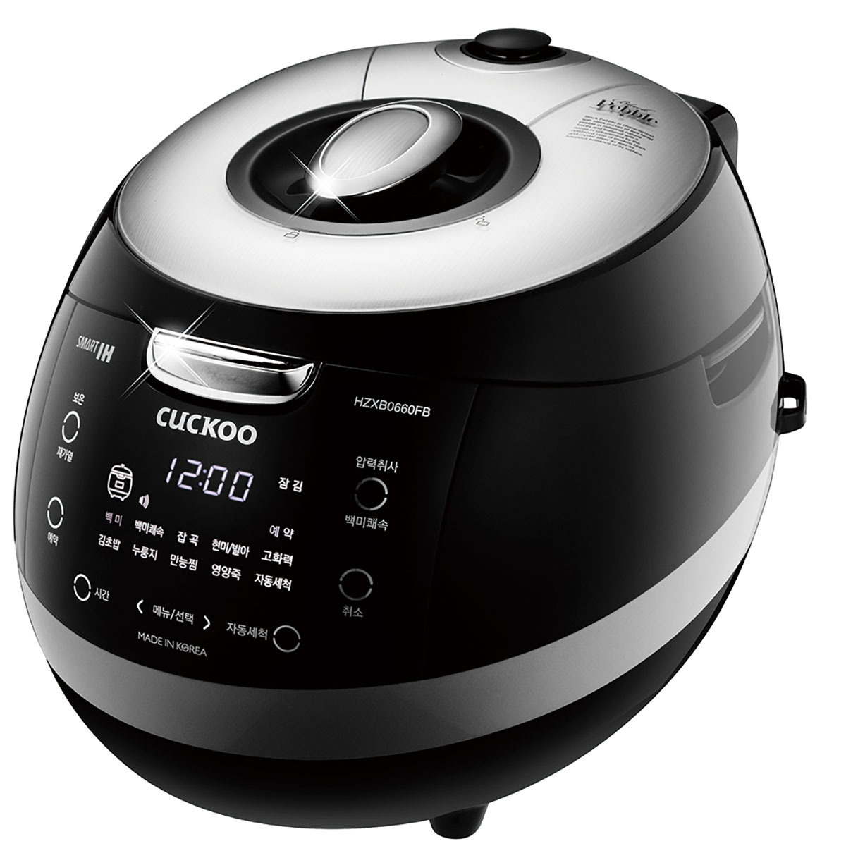
Korean rice cooker: when the rice is ready, the voice says “Delicious rice is ready to be served” and the lid automatically opens. Based on time/water level one sets, the rice cooker serves the most ideal type of rice.
Theft alarm in stores: When people walk out with a product without paying, the alarm detects it and makes a loud noise.
Automatic Cat feeder at my house: whenever it is user’s set time, the voice recording of me saying “time to eat kitties!”(which I trained my cats to come and eat when I say this) plays automatically, and the chamber inside the feeder rotates and sends out cat food.
Not related to this topic, but I also made something similar in my last semester’s class, which is an automatic feeder that detects cats movement and also a cat exerciser.
This device can recognize a secret knock pattern that’s up to 20 knocks long and unlock the door if it is correct! Instructions on how to make it can be found here.
The world’s deepest bin
This trash can makes it sound like garbage thrown in is taking a really long time. It made throwing trash away more fun and even got some people to pick up litter.
Urban Lights Contacts:
This interactive sound installation changes the sound output based on electrostatic connections; in other words, it will make varying sounds from how close people are and if people are touching. This is a really cool concept, but definitely something that would give me anxiety to try because of COVID.
Use your Arduino, speaker, and servos or solenoids to make some noise. Post something to the blog if you like, this is mostly an exercise making sure you have all the hardware we need for the Sound section.
Reading assignment: Make It So chapters 6 and 10.
Post something to Looking Outward showing use of sound in physical interaction.
I’ve added a tool that shows up in the Post editor as the icon “{…}”. To post the code below, I clicked on that icon, pasted in my code, turned off indentation, then selected C++, and hit “OK”.
// -*-c++-*-
/*
  The MIT License (MIT)

  Copyright (c) 2017 J. Eric Townsend

  Permission is hereby granted, free of charge, to any person obtaining a copy
  of this software and associated documentation files (the "Software"), to deal
  in the Software without restriction, including without limitation the rights
  to use, copy, modify, merge, publish, distribute, sublicense, and/or sell
  copies of the Software, and to permit persons to whom the Software is
  furnished to do so, subject to the following conditions:

  The above copyright notice and this permission notice shall be included in
  all copies or substantial portions of the Software.

  THE SOFTWARE IS PROVIDED "AS IS", WITHOUT WARRANTY OF ANY KIND, EXPRESS OR
  IMPLIED, INCLUDING BUT NOT LIMITED TO THE WARRANTIES OF MERCHANTABILITY,
  FITNESS FOR A PARTICULAR PURPOSE AND NONINFRINGEMENT. IN NO EVENT SHALL THE
  AUTHORS OR COPYRIGHT HOLDERS BE LIABLE FOR ANY CLAIM, DAMAGES OR OTHER
  LIABILITY, WHETHER IN AN ACTION OF CONTRACT, TORT OR OTHERWISE, ARISING FROM,
  OUT OF OR IN CONNECTION WITH THE SOFTWARE OR THE USE OR OTHER DEALINGS IN
  THE SOFTWARE.
*/

/*
  using interrupts to stop/alter a process that's eating up the loop()
cycle with delays

 */

static const int potOnPin = A1;
static const int potOffPin = A1;


static const int togglePin = 2;

static const int LED1Pin = 5;
static const int LED2Pin = 6;
static const int LED3Pin = 9;

int LEDOnDuration = 1000;  // milliseconds
int LEDOffDuration = 1000;  // milliseconds
long LEDOnTime = 0;
long LEDOffTime = 0;;
bool LEDState = false;
bool LEDStatePrev = false;
int toggleState = 0;

bool flagState = false;
const bool isInterrupt = true;

// TODO: how do we stop the for() loops so we can do another analogRead()?
void SwitchPressed()
{
    // we can set the delay to 0 and fall out of the loops
  //LEDOnDuration = 0;
  //LEDOffDuration = 0;
    // or we can modify a flag variable and use that to exit the loop
       flagState = true;
}

void setup() {
  Serial.begin(115200);

  pinMode(potOnPin, INPUT);
  pinMode(potOffPin, INPUT);
  pinMode(togglePin, INPUT);

  pinMode(LED1Pin, OUTPUT);
  pinMode(LED2Pin, OUTPUT);
  pinMode(LED3Pin, OUTPUT);

  if (isInterrupt) {
    attachInterrupt (digitalPinToInterrupt(togglePin), SwitchPressed, CHANGE);
  }
}

void loop() {

  if (!isInterrupt) {
    flagState = digitalRead(togglePin);
  }

  if (flagState) {
    Serial.println("flagState true");
  }

  // take input from the pots to determine on/off times
  int pot = analogRead(potOnPin);
  if (pot != LEDOnDuration) {
   //Serial.print("on: ");
    //Serial.println(pot);
    LEDOnDuration = map(pot, 0, 1024, 0, 255);
  }
  pot = analogRead(potOffPin);
  if (pot != LEDOffDuration) {
   // Serial.print("off: ");
   // Serial.println(pot);
    LEDOffDuration = map(pot, 0, 1024, 0, 255);
  }


  // now let's write some really bad code
  // turn the LEDs on
  for (int i = 0; i < 255; i++) {
      if (flagState) {
        break;
  // is more reliable than setting i = 256;
          // if we set flagState back to false here we
          // won't make a change in the next loop where we
          // turn LEDs off
      }
      else {
          analogWrite(LED1Pin, i);
          analogWrite(LED2Pin, i);
          analogWrite(LED3Pin, i);
          delay(LEDOnDuration);
      }
  }
  // turn the LEDs off
  for (int i = 255; i > 0; i--) {
      if (flagState) {
          break;
  // is more reliable than setting i = 256;
          // if we set flagState back to false here we
          // won't make a change in the next loop where we
          // turn LEDs on
      }
      else {
          analogWrite(LED1Pin, i);
          analogWrite(LED2Pin, i);
          analogWrite(LED3Pin, i);
          delay(LEDOffDuration);
      }
  }

  // this is the proper place to turn off the flagState.
  // We could do this with just a statement and never check
  // its status, but using a test makes debugging easier
  if (flagState == true) {
      flagState = false;
      // because we could add this
      Serial.println("flagState was on, now turned off");
  }

}
It can be very difficult for people with seeing difficulty to orient themselves. In fact, it is already difficult enough to locate the braille signs, which is supposed to help them. In addition, there are situations where visual clues are necessary, such as deciding which elevator goes up when two arrive at the same time. Here is a video that mentions such difficulty.
As a result, people with visual difficulty have to memorize routes. It is also very challenging for them to travel through a new district or locate a room in an unfamiliar building.
Solution
The key that causes this problem is the lost of visual clues. When we walk into a new building, we can look for signs for directions. When we travel through a new place, we can use google map as a guide. However, for people with seeing difficulty, the same clues are either impossible to get, like the road sings for example, or very inaccessible like the braille sign that hides behind a door.
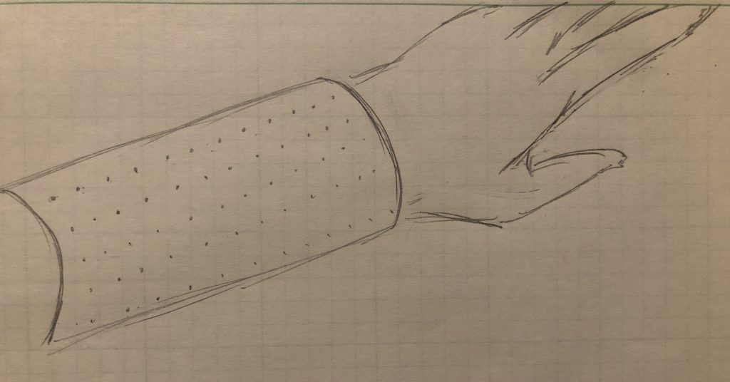
To solve this problem, I would like to translate the visual clues into braille on a device that is accessible. In other words, instead of looking for physical sign of braille, the user can read the signs in braille on a device in his or her hand. This device, however, can not only be used as a navigator but also a “seeing” tool to read the visuals in a space or environment.
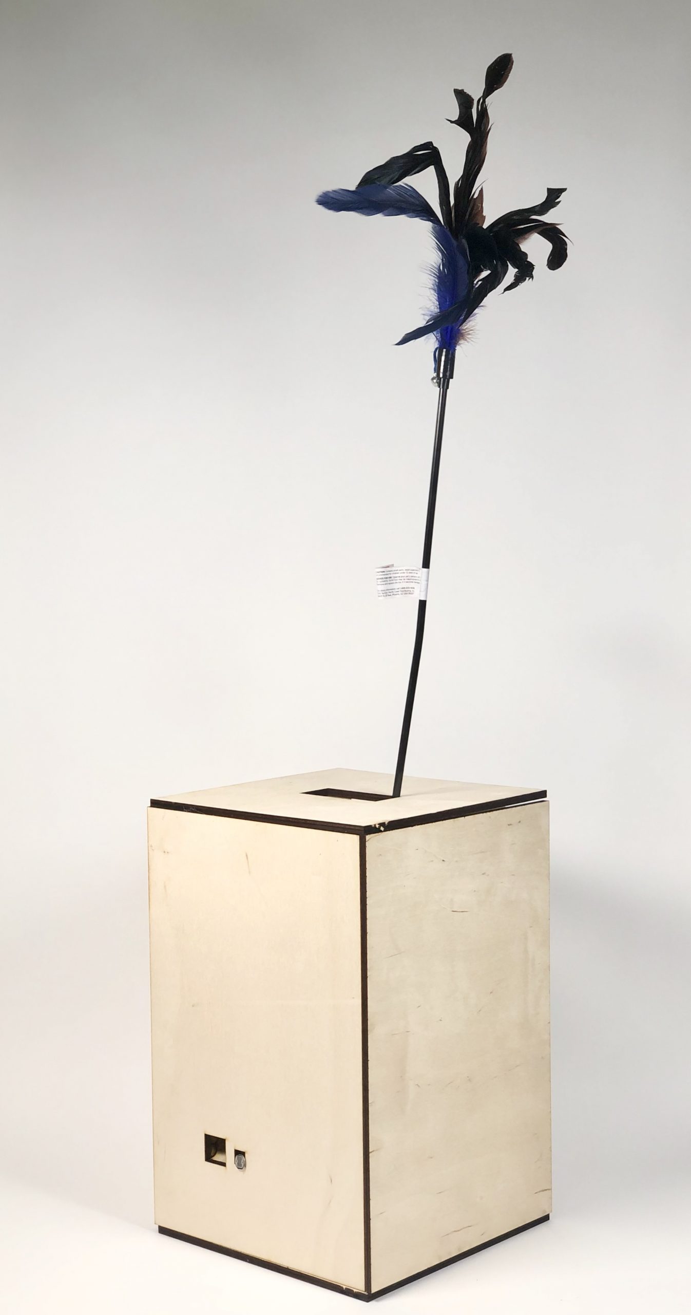
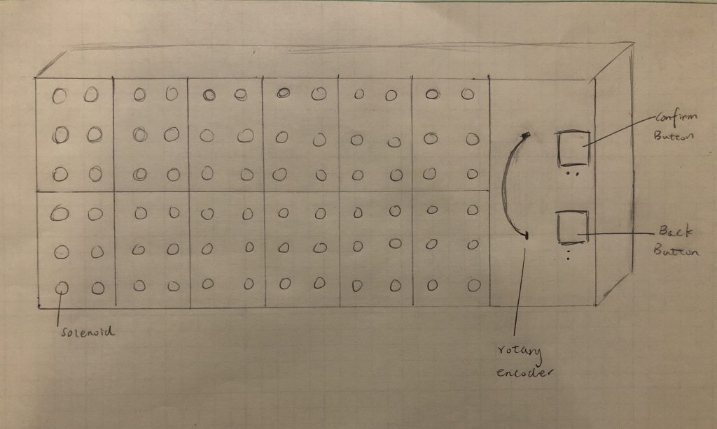
The design of the prototype
As shown in the figure above, the device have 12 digits for displaying letters and punctuations. Each digit is made of 6 solenoids and will display alphabet in braille. The rotary encode on the right is for flipping to the next 12 letters in the sentences. There are also a confirm button and a back button. This device can be connected to smart phone and indoor devices through Bluetooth or wi-fi.
Suppose a person with difficulty wants to go to new place, he or she can use app on his or her smartphone to determine the route. The person can then use the device to navigate while walking. When there are road signs or alerts that need attention, the device will vibrate and display the message. The device will go back to the route when the alert was read and confirm button pressed. The person can also use the back button to check the last direction or instruction.
Of course, the effectiveness of this device depends heavily on how small we can make it to be. With the current material of mini-solenoid, I can make it to have a length of 18 cm and a width of 7.2 cm. This cannot work effective as a navigation tool because it is too big and cumbersome. However, it can still be used while stationary such as in a restaurant, museum, and a room.
For future design
If we have the interactive surface technology in the future, this is the design I will give to the device. It wrap around the arm of the user so that the user can hold a white cane in one hand, and read the information using another hand. No more buttons and rotary encoder are needed because everything can be displayed and interacted with through the surface.
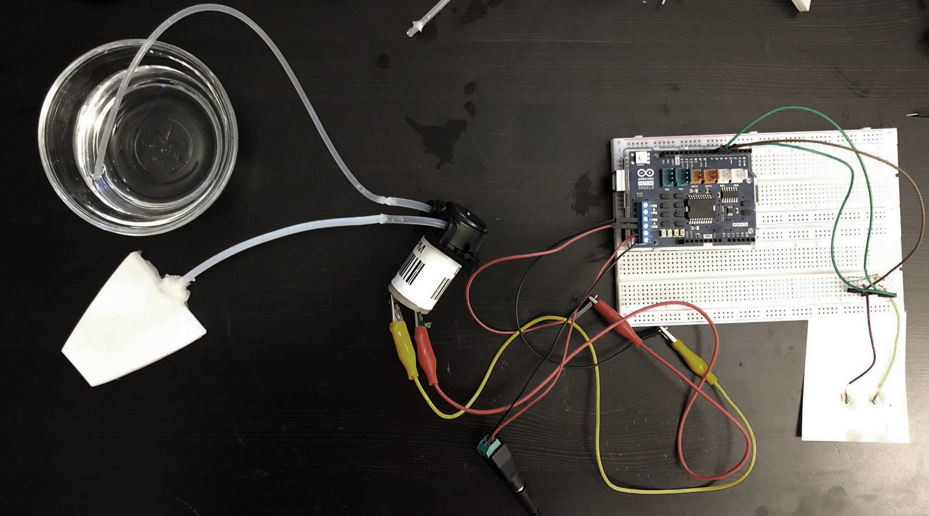
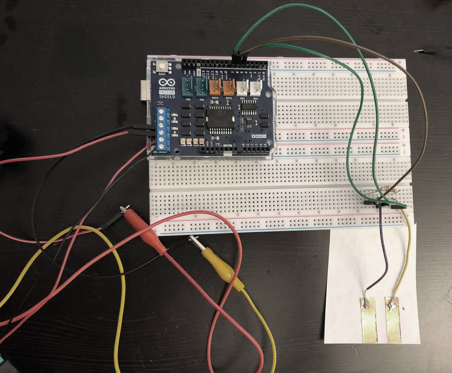
Proof of Logic
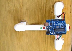
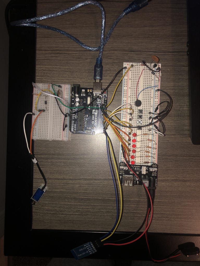
The components of the demonstration
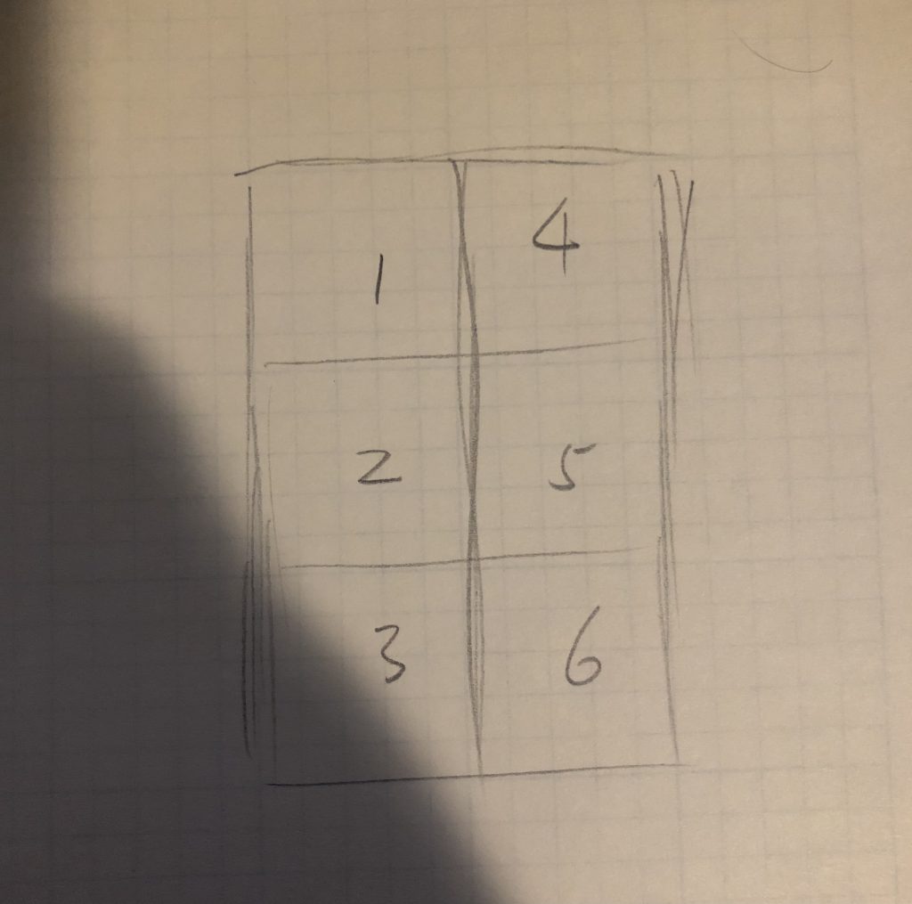
The demo is made up of a solenoid, a Bluetooth module, 6 LED, 4 buttons, and a vibration motor. The LEDs represent the 6-dot grid of the braille. The corresponding grid is shown below.
LED braille grid
Because the demo-device is relatively complex, it will be explained with video of demonstration.
This shows the normal function of the solenoid. In the later demonstration it does not function correctly due to the insufficient current arduino UNO supplies.
The two button pressed in the video represents the rotary encode that allows the user to flip to the next or previous 12 letters.
The buttons pressed in the video are confirm button and back button, which allows the user to display the next or previous message instruction.
Finally, in the video alerts are sent from the PC to the device through Bluetooth. The device then vibrate and display the alert with the corresponding braille letter.
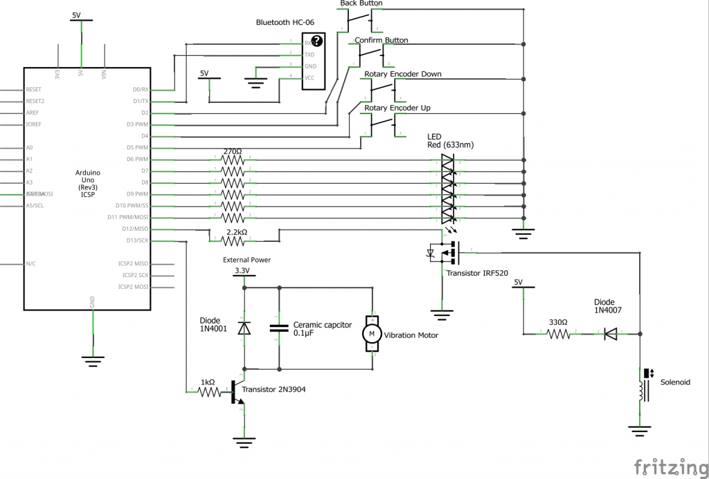
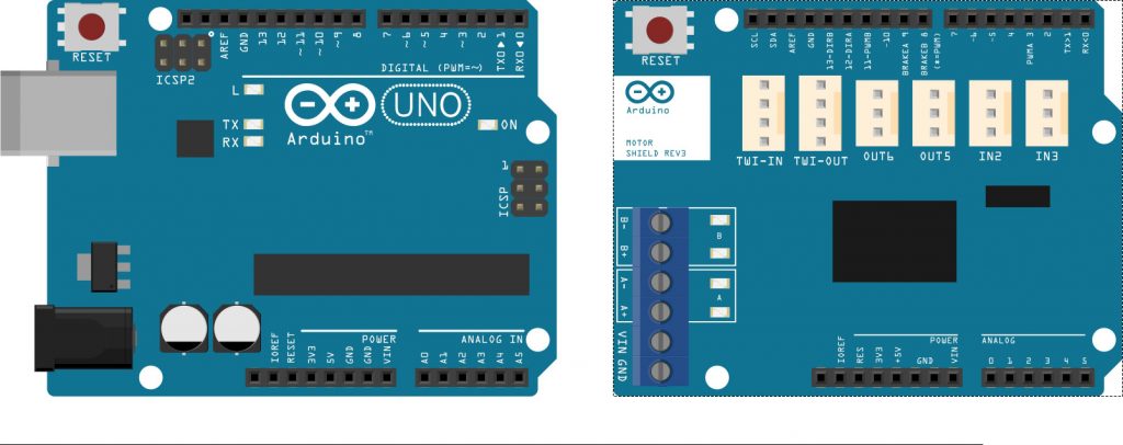
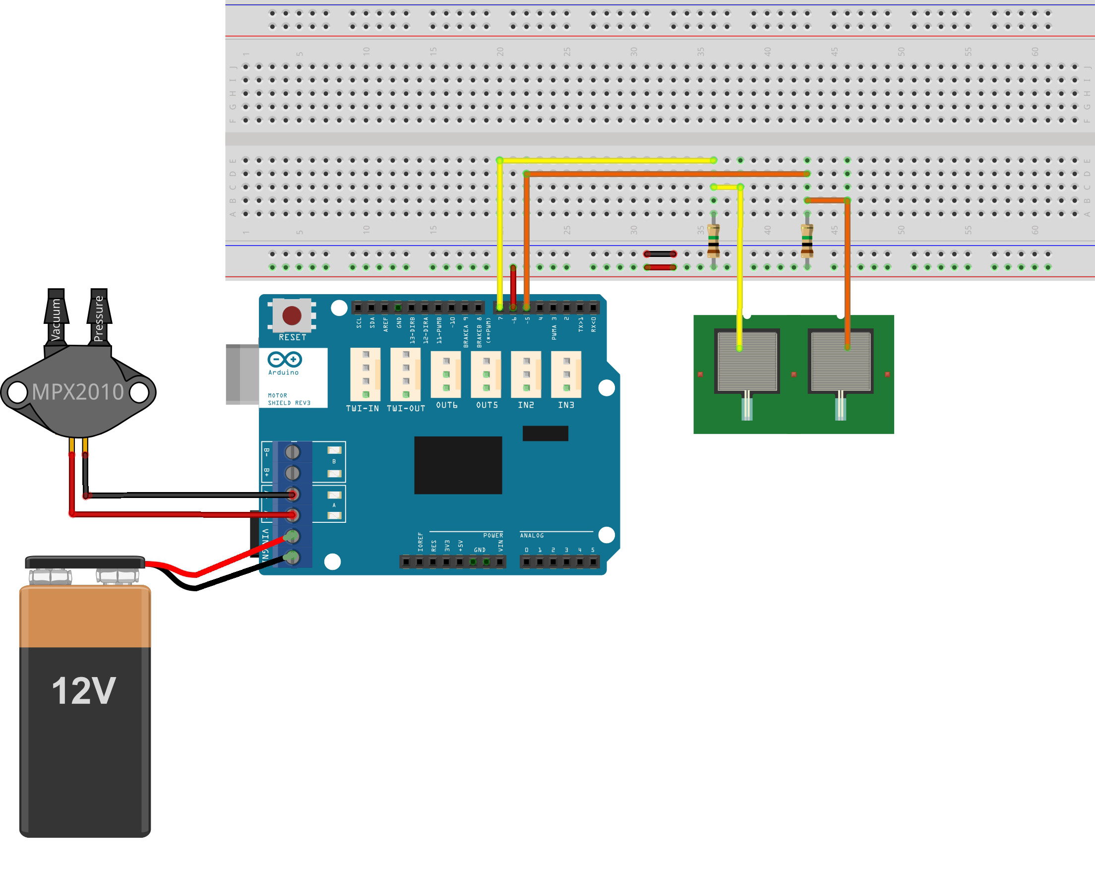
Schematic:
Code:
//Defining the pins
#define solenoide 12
#define motor 13
#define rotary_up 5
#define rotary_down 4
#define confirm 3
#define back 2
#define LED1 11
#define LED2 10
#define LED3 9
#define LED4 8
#define LED5 7
#define LED6 6

//Variables
//constant variables
char *INPUT_STRINGS[] = {"information destk is at first floor","elevator is to the right by ten meters" ,"this is room b ten"};

//Message is like the route and direction
int message;
int message_length;
String string;
int start_letter;

//Alert is like the signs or alerts on the street or in buildings
String incoming_alert; //string that stores the incoming message
String alert[5];
int alert_index;
bool has_alert;
bool vibration_on;

//variable for interrupt, note that message is also a ISR variable
const bool isInterrupt = true;
int message_number = 3;

//timer
//Clock 1 is the timer for checking the rotary encoder
unsigned long clock1 = 0; // variable for timing
const int INTERVAL1 = 300; // milliseconds between updates

//Clock 2 is for serial printing for illustration
unsigned long clock2 = 0; // variable for timing
const int INTERVAL2 = 2000; // milliseconds between updates

//Clock 3 is for serial printing for illustration
unsigned long clock3 = 0; // variable for timing
const int INTERVAL3 = 1500; // milliseconds between updates


// the interrupt method
// NOTE:  we shouldn't use Serial.prinln(), delay(), and many
// other functions in an interrupt method
void ConfirmSwitchPressed()
{
  if (digitalRead(confirm) == LOW) {
    if (has_alert == true) {
      //alert index also show how many alerts are in the alert array
      if (alert_index == 1) {
        has_alert = false;
      }

      for (int i; i < alert_index; i++) {
        alert[i] = alert[i + 1];
      }

      if (alert_index != 0) {
        alert_index -= 1;
      }

      Serial.println("Alert read");
      return;
    }


    if (has_alert == false) {
      message == message_number ? message = 0 : message++;
      start_letter = 0;

      Serial.println("Next Message");
    }
  }
}

void BackSwitchPressed()
{
  if (digitalRead(back) == LOW) {

    if (has_alert == false) {
      message == 0 ? message = message_number : message--;
      start_letter = 0;

      Serial.println("Previous Message");
    }
  }
}

//Functions
//demonstration function that shows how to move solenoid
void move_solenoid() {
  digitalWrite(solenoide, HIGH);
  delay(1000);
  digitalWrite(solenoide, LOW);
  delay(1000);
}

//Demonstration function
void vibrate_motor() {
  digitalWrite(motor, HIGH);
  delay(2000);
  digitalWrite(motor, LOW);
  delay(2000);
}


void show_letters() {
  if (has_alert == true) {
    braille(alert[0][start_letter]);
  }

  if (has_alert == false) {
    braille(INPUT_STRINGS[message][start_letter]);
  }

  //if there are actually 12 digits, each made of 6 solenoid
  //int digit;
  //for (i=start_letter, i< start_letter +13,i++) {
  //     braille(digit, INPUT_STRINGS[message][start_letter + i])
  //     digit += 1;
  //    }
}

//This function put the incoming alert into the alert array
void insert_alert() {
  //-1 indicates that there is no \ in the alert message
  int null_index = incoming_alert.indexOf('.');
  if (null_index != -1 and alert_index < 4) {
    alert[alert_index] = incoming_alert.substring(0, null_index);
    alert_index += 1;
    //Tell the system there are alerts
    has_alert = true;

    //Turn the vibration and its corresponding timer on
    digitalWrite(motor, HIGH);
    vibration_on = true;
    clock3 = millis() + INTERVAL3;

    //Clear the string for the next incoming alert
    incoming_alert = "";

    Serial.print("Alert received, ");
    Serial.println("vibration on.");
  }
}


//In the actual desgin instead of this demo, the 6 LEDs are 6 solenoides
void braille(char input) {
  digitalWrite(LED1, LOW);
  digitalWrite(LED2, LOW);
  digitalWrite(LED3, LOW);
  digitalWrite(LED4, LOW);
  digitalWrite(LED5, LOW);
  digitalWrite(LED6, LOW);
  digitalWrite(solenoide, LOW);


  if (input == 'a') {
    digitalWrite(LED1, HIGH);

    digitalWrite(solenoide, HIGH);
  }

  if (input == 'b') {
    digitalWrite(LED1, HIGH);
    digitalWrite(LED2, HIGH);

    digitalWrite(solenoide, HIGH);
  }

  if (input == 'c') {
    digitalWrite(LED1, HIGH);
    digitalWrite(LED4, HIGH);

    digitalWrite(solenoide, HIGH);
  }

  if (input == 'd') {
    digitalWrite(LED1, HIGH);
    digitalWrite(LED4, HIGH);
    digitalWrite(LED5, HIGH);

    digitalWrite(solenoide, HIGH);
  }

  if (input == 'e') {
    digitalWrite(LED1, HIGH);
    digitalWrite(LED5, HIGH);

    digitalWrite(solenoide, HIGH);
  }

  if (input == 'f') {
    digitalWrite(LED1, HIGH);
    digitalWrite(LED2, HIGH);
    digitalWrite(LED5, HIGH);

    digitalWrite(solenoide, HIGH);
  }

  if (input == 'g') {
    digitalWrite(LED1, HIGH);
    digitalWrite(LED2, HIGH);
    digitalWrite(LED4, HIGH);
    digitalWrite(LED5, HIGH);

    digitalWrite(solenoide, HIGH);
  }

  if (input == 'h') {
    digitalWrite(LED1, HIGH);
    digitalWrite(LED2, HIGH);
    digitalWrite(LED5, HIGH);

    digitalWrite(solenoide, HIGH);
  }

  if (input == 'i') {

    digitalWrite(LED2, HIGH);
    digitalWrite(LED4, HIGH);

  }

  if (input == 'j') {
    digitalWrite(LED2, HIGH);
    digitalWrite(LED4, HIGH);
    digitalWrite(LED5, HIGH);
  }

  if (input == 'k') {
    digitalWrite(LED1, HIGH);
    digitalWrite(LED3, HIGH);

    digitalWrite(solenoide, HIGH);

  }

  if (input == 'l') {
    digitalWrite(LED1, HIGH);
    digitalWrite(LED2, HIGH);
    digitalWrite(LED3, HIGH);

    digitalWrite(solenoide, HIGH);
  }

  if (input == 'm') {
    digitalWrite(LED1, HIGH);
    digitalWrite(LED3, HIGH);
    digitalWrite(LED4, HIGH);

    digitalWrite(solenoide, HIGH);
  }

  if (input == 'n') {
    digitalWrite(LED1, HIGH);
    digitalWrite(LED5, HIGH);
    digitalWrite(LED3, HIGH);
    digitalWrite(LED4, HIGH);

    digitalWrite(solenoide, HIGH);
  }

  if (input == 'o') {
    digitalWrite(LED1, HIGH);
    digitalWrite(LED5, HIGH);
    digitalWrite(LED3, HIGH);

    digitalWrite(solenoide, HIGH);
  }

  if (input == 'p') {
    digitalWrite(LED1, HIGH);
    digitalWrite(LED2, HIGH);
    digitalWrite(LED3, HIGH);
    digitalWrite(LED4, HIGH);

    digitalWrite(solenoide, HIGH);
  }

  if (input == 'q') {
    digitalWrite(LED1, HIGH);
    digitalWrite(LED2, HIGH);
    digitalWrite(LED3, HIGH);
    digitalWrite(LED4, HIGH);
    digitalWrite(LED5, HIGH);

    digitalWrite(solenoide, HIGH);
  }


  if (input == 'r') {
    digitalWrite(LED1, HIGH);
    digitalWrite(LED2, HIGH);
    digitalWrite(LED3, HIGH);
    digitalWrite(LED5, HIGH);

    digitalWrite(solenoide, HIGH);
  }


  if (input == 's') {
    digitalWrite(LED2, HIGH);
    digitalWrite(LED3, HIGH);
    digitalWrite(LED4, HIGH);

  }


  if (input == 't') {
    digitalWrite(LED2, HIGH);
    digitalWrite(LED3, HIGH);
    digitalWrite(LED4, HIGH);
    digitalWrite(LED5, HIGH);
  }


  if (input == 'u') {
    digitalWrite(LED1, HIGH);
    digitalWrite(LED3, HIGH);
    digitalWrite(LED6, HIGH);

    digitalWrite(solenoide, HIGH);
  }


  if (input == 'v') {
    digitalWrite(LED1, HIGH);
    digitalWrite(LED2, HIGH);
    digitalWrite(LED3, HIGH);
    digitalWrite(LED6, HIGH);

    digitalWrite(solenoide, HIGH);

  }


  if (input == 'w') {

    digitalWrite(LED2, HIGH);
    digitalWrite(LED6, HIGH);
    digitalWrite(LED4, HIGH);
    digitalWrite(LED5, HIGH);
  }


  if (input == 'x') {
    digitalWrite(LED1, HIGH);
    digitalWrite(LED3, HIGH);
    digitalWrite(LED4, HIGH);
    digitalWrite(LED6, HIGH);

    digitalWrite(solenoide, HIGH);
  }


  if (input == 'y') {
    digitalWrite(LED1, HIGH);
    digitalWrite(LED6, HIGH);
    digitalWrite(LED3, HIGH);
    digitalWrite(LED4, HIGH);
    digitalWrite(LED5, HIGH);

    digitalWrite(solenoide, HIGH);
  }


  if (input == 'z') {
    digitalWrite(LED1, HIGH);
    digitalWrite(LED6, HIGH);
    digitalWrite(LED3, HIGH);
    digitalWrite(LED5, HIGH);

    digitalWrite(solenoide, HIGH);
  }


  if (input == ',') {
    digitalWrite(LED2, HIGH);
  }


  if (input == '.') {
    digitalWrite(LED2, HIGH);
    digitalWrite(LED6, HIGH);
    digitalWrite(LED5, HIGH);
  }

  if (input == '!') {
    digitalWrite(LED2, HIGH);
    digitalWrite(LED3, HIGH);
    digitalWrite(LED5, HIGH);
  }
}


void setup() {
  // Setup the pin modes
  pinMode(solenoide, OUTPUT);
  pinMode(motor, OUTPUT);
  pinMode(LED1, OUTPUT);
  pinMode(LED2, OUTPUT);
  pinMode(LED3, OUTPUT);
  pinMode(LED4, OUTPUT);
  pinMode(LED5, OUTPUT);
  pinMode(LED6, OUTPUT);


  //When the buttons are pushed, digitalRead shows 0
  pinMode(rotary_up, INPUT_PULLUP);
  pinMode(rotary_down, INPUT_PULLUP);
  pinMode(confirm, INPUT_PULLUP);
  pinMode(back, INPUT_PULLUP);


  //Initiate the serial monitor
  Serial.begin(9600);

  // attach the interrupt pin to a method
  if (isInterrupt) {
    attachInterrupt (digitalPinToInterrupt(confirm), ConfirmSwitchPressed, FALLING);
    attachInterrupt (digitalPinToInterrupt(back), BackSwitchPressed, FALLING);
  }


}


void loop() {
  //Determining the number of messages/alerts and the length of each message

  if (has_alert == true) {
    string = alert[0];
    message_length = string.length();
  }

  if (has_alert == false) {
    string = INPUT_STRINGS[message];
    message_length = string.length();
  }

  //Receiving the characters of incoming alerts
  while (Serial.available()) {
    //while there is data available on the serial monitor
    //Serial.println(Serial.read());
    incoming_alert += char(Serial.read()); //store string from serial command
  }

  insert_alert();

  //Check if any movement has been made on the rotary encoder
  if (millis() >=  clock1) {

    if (digitalRead(rotary_up) == LOW) {
      if (start_letter + 12 <= message_length) {
        start_letter += 12;
        Serial.println("Next 12 letters");
      }
    }

    if (digitalRead(rotary_down) == LOW) {
      if (start_letter - 12 >= 0)  {
        start_letter -= 12;
        Serial.println("Last 12 letters");
      }
    }

    clock1 = millis() + INTERVAL1 ;

  }

  show_letters();

  //For serial printing of demonstration
  if (millis() >=  clock2) {

    if (incoming_alert != "") {
      Serial.print("Incoming Alert: ");
      Serial.println(incoming_alert);
    }

    //Serial.print("The current message or alert: ");
    Serial.println(string);


    clock2 = millis() + INTERVAL2 ;

  }

  //For 2-second duration of the vibration motor
  if (millis() >=  clock3 and vibration_on == true) {
    digitalWrite(motor, LOW);
    vibration_on = false;
    Serial.println("vibration off.");
  }


}
Do you like having natural light in the room during the day, but often forget to close the curtains at night and so get woken up earlier than you wanted in the morning? Do you ever just want to wake up with natural light in the room, but not get woken up too early by it? After not getting enough sleep, do you find yourself having trouble getting up to your alarm or being blinded when you turn on the light or open the curtains because your eyes aren’t used to it? If you’re like me and have answered yes to these questions, this worry free curtain and alarm clock supplement could be the solution!
Proposed Solution:
Enter the time times you want to wake up each day of the week, the current date and time, upload the program, and that’s it your curtains will open according to the time you want to wake up and when you went to bed (set by pressing button) and close when it’s evening and dark. If you didn’t get nearly enough sleep, a fan will also blow in your face when your alarm goes off to help ensure you wake up. The fan could be an overhead one, but one on a nightstand or a taller one on the floor next to the bed would be best. I used the left and right threaded rods coupled together that I had from a previous project to be able to control the open and closing of the curtains movement. The logic I used for when the curtains should open compared to when you want to wake up and when you went to sleep were set by my preferences wherein the less sleep I got, the earlier the curtains would open based on time frames of amount of sleep. For me if I’ve gotten less sleep, I wake up to slight changes less than if I got enough sleep. Also, the fan is set to blow at a low speed for a minute when you’ve had under 5 hours sleep and high speed for 30 seconds if you’ve had between 5 and 6 hours. This is because higher speed will be more annoying and so needs to be on less; the lower speed is for the least sleep case because you are more likely to get sick on less sleep. I used a stepper motor to control the opening and closing of the curtains as that is what I had available and I can easily control the distance moved forward and reverse precisely. I would’ve used a faster motor if available and ideally a DC motor and an encoder instead as I’d be able to control the amounts forward and reverse easily and it’s more efficient in this scenario. Additionally, if I had a pressure sensor, the time you went to bed would be detected by the time you went on the bed and didn’t get up again before the alarm. This way you wouldn’t have to remember to click a button. To add to this, I would add a speaker so that this could be used for an alarm sound itself too. Finally, as someone mentioned during the crit, an app would be really useful for inputting the parameters and quickly making any changes. With the materials I was able to use and the time given, I’m happy with this prototype and in the future may make this for myself on an actual scale.
For reference, this is what the curtains in my room look like:
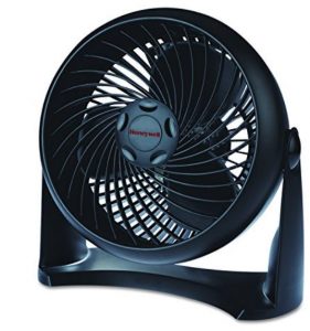
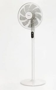
Ideal fans:
small fan for nightstandfloor stand fan to be put near head of bed
Proof of Concept:
Closing the curtains after 6:00PM and dark
Setting the time went to bed, opening curtains, and blowing the fan.
You might notice that in this video, the printing format changed from day, month, year to month, day, year. This was an intentional change after the first video because it’s the format we are accustomed to.
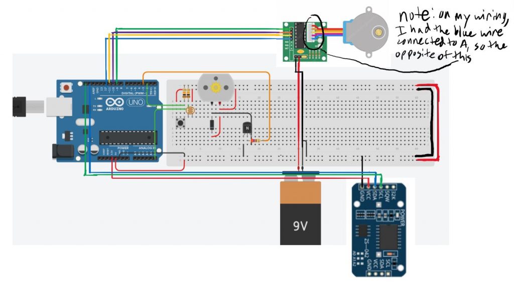
Circuit
#include <AccelStepper.h>

// stepper Motor pin definitions:
#define motorPin1  9      // IN1 on the ULN2003 driver
#define motorPin2  10      // IN2 on the ULN2003 driver
#define motorPin3  11     // IN3 on the ULN2003 driver
#define motorPin4  12     // IN4 on the ULN2003 driver

// Define the AccelStepper interface type; 4 wire motor in half step mode:
#define MotorInterfaceType 8

// Initialize with pin sequence IN1-IN3-IN2-IN4 for using the AccelStepper library with 28BYJ-48 stepper motor:
AccelStepper stepper = AccelStepper(MotorInterfaceType, motorPin1, motorPin3, motorPin2, motorPin4);
//above from  https://www.makerguides.com to learn how to use this specific stepper motor and driver

#include <Wire.h>
#include <RTC.h>
const int photoPin = A5;
static DS3231 RTC;

//input times for each day with hr then min; 24 hr time but as it'll be morning, it shouldn't make too much of a difference
int wakeUpTimes[7][2] ={{12, 12}, //sun
                        {9, 0}, //mon
                        {9, 35}, //tues
                        {8, 55}, //wed
                        {9, 30}, //thurs
                        {10, 10}, //fri
                        {11, 11}};//sat

const int fanMotorPin = 3;
int low = 50;
int high = 150;
int fanSpeed;
int turnOnFan;
int fanDuration;

int timeSlept[3];
int openCurtainsXbeforeWakeUpTime;
int sleep = 0;
const int buttonPin = 2;

int timeWentToBed[3];

void calcTimeSlept() {
  //seconds
  int secs = 60 - timeWentToBed[0];
  if (secs == 60) {
    timeSlept[2] = 0;
  }
  else {
    timeSlept[2] = secs;
  }

  //mins
  if (wakeUpTimes[RTC.getWeek() - 1][1] >= timeWentToBed[1]) {
    if (timeSlept[2] == 0) {
      timeSlept[1] = wakeUpTimes[RTC.getWeek() - 1][1] - timeWentToBed[1];
    }
    else {
      timeSlept[1] = wakeUpTimes[RTC.getWeek() - 1][1] - timeWentToBed[1] - 1;
    }
  }
  else {
    if (timeSlept[2] == 0) {
      timeSlept[1] = wakeUpTimes[RTC.getWeek() - 1][1] + 60 - timeWentToBed[1];
    }
    else {
      timeSlept[1] = wakeUpTimes[RTC.getWeek() - 1][1] + 60 - timeWentToBed[1] - 1;
    }
  }

  //hrs
  if (timeWentToBed[0] < 12) {
    if (wakeUpTimes[RTC.getWeek() - 1][1] >= timeWentToBed[1]) {
      timeSlept[0] = wakeUpTimes[RTC.getWeek() - 1][0] - timeWentToBed[0];
    }
    else {
      timeSlept[0] = wakeUpTimes[RTC.getWeek() - 1][0] - timeWentToBed[0] - 1;
    }
  }
  else { //if went to bed before midnight, need to add hours bc subtraction not right otherwise
    int hrsBeforeMidnight = 24 - timeWentToBed[0];
    if (wakeUpTimes[RTC.getWeek() - 1][1] >= timeWentToBed[1]) {
      timeSlept[0] = wakeUpTimes[RTC.getWeek() - 1][0] + hrsBeforeMidnight;
    }
    else {
      timeSlept[0] = wakeUpTimes[RTC.getWeek() - 1][0] + hrsBeforeMidnight - 1;
    }
  }
}

void goinToSleep() {
  if (digitalRead(buttonPin) == HIGH) {
    sleep = 1;
  }
}

void openCurtains() {
  while (stepper.currentPosition() != 4096 * 7) { //choosing this bc it was enough rev to at least show some opening
    stepper.setSpeed(1000);
    stepper.runSpeed();
  }
}
void closeCurtains() {
  while (stepper.currentPosition() != 0) {
    stepper.setSpeed(-1000);
    stepper.runSpeed();
  }
}

void setup() {
  // put your setup code here, to run once:
  stepper.setMaxSpeed(1000);
  Serial.begin(9600);
  RTC.begin();

  RTC.setDay(16);
  RTC.setMonth(10);
  RTC.setYear(2020);

  RTC.setWeek(6);

//to show setting time went to bed from button for Fri
  RTC.setHours(10);
  RTC.setMinutes(8);
  RTC.setSeconds(0);

//to show fan turning on when not enough sleep for Mon
//  RTC.setHours(8);
//  RTC.setMinutes(59);
//  RTC.setSeconds(30);

////to show closing:
//  stepper.setCurrentPosition(4096 * 7);

  //to show curtains closing past 5 and dark
//  RTC.setHours(17);
//  RTC.setMinutes(59);
//  RTC.setSeconds(45);

//to show opening:
    stepper.setCurrentPosition(0);
  //to show curtain opening:
//  RTC.setHours(8);
//  RTC.setMinutes(49);
//  RTC.setSeconds(58);

  RTC.setHourMode(CLOCK_H24);

  pinMode(fanMotorPin, OUTPUT);

  attachInterrupt (digitalPinToInterrupt (buttonPin), goinToSleep, HIGH);

  /*set time went to bed to hr before wakeup as default after woken up
        will change if/when press button before going to sleep
        this way if you forget still get this, and assuming if didn't press,
        you went to bed really late
  */
  //commenting out for demo of button to set time went to bed
  timeWentToBed[0] = wakeUpTimes[RTC.getWeek() - 1][0] - 1;
  timeWentToBed[1] = wakeUpTimes[RTC.getWeek() - 1][1];
  timeWentToBed[2] = 0;
}

void loop() {
  int  photoVal = analogRead(photoPin);
  //Serial.println(photoVal);
  if (RTC.getHours() >= 18) {//6:00PM
    if (photoVal < 600) {
      //if it's past 6PM and dark(here just chose 600, but would be lower in real thing), close curtains
      closeCurtains();
    }
  }
  if (sleep == 1) {
    Serial.println("clicked");
    timeWentToBed[0] = RTC.getHours();
    timeWentToBed[1] = RTC.getMinutes();
    timeWentToBed[2] = RTC.getSeconds();
    calcTimeSlept();
    sleep = 0;
  }
  if (timeSlept[0] >= 8) {
    openCurtainsXbeforeWakeUpTime = 5; //mins
  }
  else if (6 <= timeSlept[0] && timeSlept[0] < 8) {
    openCurtainsXbeforeWakeUpTime = 30; //mins
  }
  else if (5 <= timeSlept[0] && timeSlept[0] < 6) {
    openCurtainsXbeforeWakeUpTime = 45; //mins
    turnOnFan = 1;
    fanSpeed = high;
    fanDuration = 30;
  }
  else {//under 5 hrs
    //for demo
    //openCurtainsXbeforeWakeUpTime = 1; //mins
    openCurtainsXbeforeWakeUpTime = 55; //mins
    turnOnFan = 1;
    fanSpeed = low;
    fanDuration = 60;
  }
  if (wakeUpTimes[RTC.getWeek() - 1][1] >= openCurtainsXbeforeWakeUpTime) {
    if (RTC.getHours() == wakeUpTimes[RTC.getWeek() - 1][0]) {
//Serial.println(openCurtainsXbeforeWakeUpTime);
        //Serial.println((wakeUpTimes[RTC.getWeek() - 1][1] - openCurtainsXbeforeWakeUpTime));
      if (RTC.getMinutes() == (wakeUpTimes[RTC.getWeek() - 1][1] - openCurtainsXbeforeWakeUpTime)) {
        openCurtains();
        timeWentToBed[0] = wakeUpTimes[RTC.getWeek() - 1][0] - 1;
        timeWentToBed[1] = wakeUpTimes[RTC.getWeek() - 1][1];
        timeWentToBed[2] = 0;
      }
    }
  }
  else {//minutes of wakeUpTime<time to subtract to wake up
    if (RTC.getHours() == (wakeUpTimes[RTC.getWeek() - 1][0] - 1)) { //took hr off here
      //right side of eq subtracted amount of time left after changing hr
      if (RTC.getMinutes() == (60 - openCurtainsXbeforeWakeUpTime + wakeUpTimes[RTC.getWeek() - 1][1])) {
        openCurtains();
        timeWentToBed[0] = wakeUpTimes[RTC.getWeek() - 1][0] - 1;
        timeWentToBed[1] = wakeUpTimes[RTC.getWeek() - 1][1];
        timeWentToBed[2] = 0;
      }
    }
  }

  if (RTC.getHours() == wakeUpTimes[RTC.getWeek() - 1][0]) {
    if (RTC.getMinutes() == wakeUpTimes[RTC.getWeek() - 1][1]) {
      //Serial.println(RTC.getSeconds());
      if (turnOnFan) {
        if (RTC.getSeconds() <= fanDuration) {
          //Serial.println(RTC.getSeconds());
          analogWrite(fanMotorPin, fanSpeed);
        }
        else {
                    analogWrite(fanMotorPin, 0);
          turnOnFan = 0;
          }
      }

    }
  }
  static int startPrint=millis();
  if ((millis()-startPrint)>=1000){//putting this here so don't use delay while also showing the times
   switch (RTC.getWeek())
    {
      case 1:
        Serial.print("SUN");
        break;
      case 2:
        Serial.print("MON");
        break;
      case 3:
        Serial.print("TUE");
        break;
      case 4:
        Serial.print("WED");
        break;
      case 5:
        Serial.print("THU");
        break;
      case 6:
        Serial.print("FRI");
        break;
      case 7:
        Serial.print("SAT");
        break;
    }
    Serial.print(" ");
    Serial.print(RTC.getMonth());
    Serial.print("-");
    Serial.print(RTC.getDay());
    Serial.print("-");
    Serial.print(RTC.getYear());

    Serial.print(" ");

    Serial.print(RTC.getHours());
    Serial.print(":");
    Serial.print(RTC.getMinutes());
    Serial.print(":");
    Serial.println(RTC.getSeconds());

    startPrint=millis();
  }
  //  delay(1000);
}
Problem:
As we transition into a working from home setup during covid, we lose alot of the immediate feedback through body language and facial cues from people we are communicating with. In particular, this is pronounced in a presenting information to a large group of people, where a successful presentation relies on tailoring the speed, complexity and cadence to engage the audience sufficiently to keep them interested, but not go too fast that you leave them behind.
When presenting a deck through online meeting platforms, presenters are often unable to monitor the real-time vibe of the audience since participants are not always visible due to screen real-estate (assuming that they have their cameras on). Even with the hand-raise feature, it’s hard for presenters to respond to questions in a timely manner.
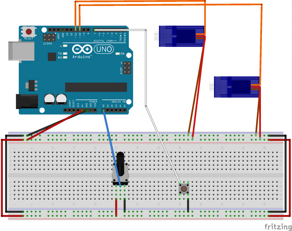
Solution:
I identified two main modes of feedback that are most important to a presenter:
Are there any questions?
Are people paying attention?
Raising your hand
To indicate if the audience has any questions, I used a servo as a physical indicator of the presence of questions. Typically, when participants raise their hands during a meeting virtually, this is missed. By mapping this state to the servo, presenters now have a better understanding of when exactly questions are being raised.
Paying attention
One of the indicators of restlessness in your audience is fidgeting. If people are bored and unable to pay attention, they are likely to be crossing their arms, rearranging their seating posture, etc. We can monitor this by observing the rate of change in their posture. Using the poseNet in p5.js, we can abstract this information by drawing keypoints of your posture in the webcam and do a comparison.
I wasn’t quite able to get the serial output from p5.js to work, so I replaced it with a potentiometer as an abstraction for the demo 🙁
Kinetic feedback
By translating this to a tapping pattern if the changes exceed a particular threshold, presenters are able to understand when their audience get restless.
It is hard to discern the nuances if the tapping pattern were to change incrementally, so I set up 3 states with a threshold rate of change that matches 3 different tapping states.
1 No need to worry
Some movement is to be expected in the audience, so presenters don’t need to be concerned about a non-zero level of movement.
2 Antsy
When the audience starts getting restless, the tapping starts with a lower frequency. The presenter can quickly re-engage the audience by speeding up and moving on. As the audience returns back to normal and pays attention, the tapping should cease.
3 I can’t stand this anymore
If the audience crosses the second threshold indicating restlessness, the frequency of taps doubles and conveys to the presenter that they should try to wrap up the presentation ASAP since they’ve likely already lost their audience.
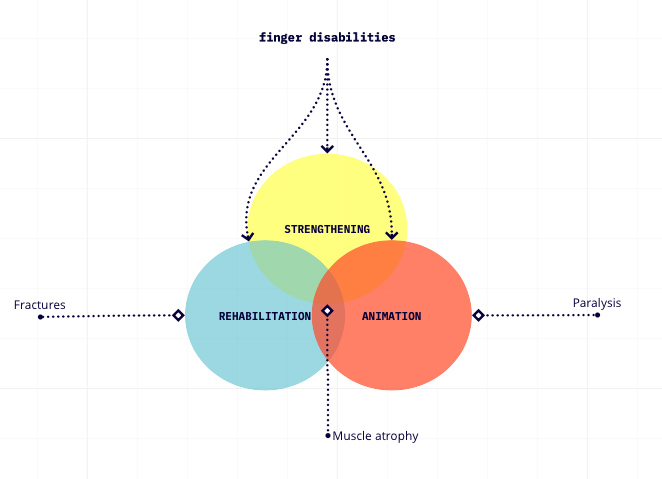
PROBLEM: People experiencing finger -specific motor disabilities are often asked to participate in rehabilitation sessions, either within clinical settings or at home. Unfortunately, a lot of them (including me) do not execute the instructed exercises for finger strengthening and as a result their traumatised fingers may not fully recover back to their original potential.
SOLUTION: RehabActuators constitute a portable, soft robotic wearable that exploits tangible interaction to motivate patients to execute finger exercises like bending/unbending. RehabActuators turns rehabilitation into a playful activity, where the participant can manipulate its own finger by using interacting with the interface.