#include "SoftwareSerial.h"
#include "DFRobotDFPlayerMini.h"
#include <LiquidCrystal_I2C.h>
SoftwareSerial mySoftwareSerial(6, 7); // RX, TX
DFRobotDFPlayerMini myDFPlayer;
void printDetail(uint8_t type, int value);
LiquidCrystal_I2C screen(0x27, 16, 2);
RF24 radio(8, 9); // CE, CSN
const int ROTARY_DOWN = 4;
const int ROTARY_CONFRIM = 3;
const int BACK_LYRICS = 2;
const int VOLUME_CONTROL = A0;
int ButtonState_rotaryUp;
int ButtonState_rotaryDown;
int ButtonState_Back_Lyrics;
int lastButtonState_rotaryUp = HIGH;
int lastButtonState_rotaryDown = HIGH;
int lastButtonState_Confirm = HIGH;
int lastButtonState_Back_Lyrics = HIGH;
unsigned long lastDebounceTime = 0; // the last time the output pin was toggled
unsigned long debounceDelay = 50; // the debounce time; increase if the output flickers
//The variables related to display the lyrics
//This is for counting the time when lyrics are displayed throughout the song.
unsigned long lyrics_timer_Start;
unsigned long lyrics_time;
unsigned long lyrics_time_oponent;
unsigned long accelerometer_timer_Start;
unsigned long accelerometer_time;
//Exercise for 10 seconds to get a chance for jackpot
const unsigned long accelerometer_time_jackpot = 10000;
//The variables used in building the interface
String interFace = "Menu";
String interFace_Secondary;
int interFace_Option = 1;
unsigned long Jackpot_Clock;
const int OneDay = 60000; //For demo purpose 1_Day is 1 minute.
unsigned long Receive_Clock;
bool song_received = false;
//Can't read the number of file yet in the global scope so make the array as big as the capacity of the SD card. Or assume the information is already given when the songs are downloaded from internet.
//The sizes of the array are set for the demo purpose
//Arrary that includes all the unlocked songs
int input_indice_unlocked;
//Array taht includes the unlocked 2010s movie soundtrack
int Unlocked_2010s_Movie[1];
int Unlocked_2010s_Pop[1];
int Unlocked_50s_Jazz[3];
//Transceiver's addresses
//One for writing and one for reading
const byte addresses[][6] = {"00001", "00002"};
//Functions related to the MP3 player
void read_information() {
Serial.println(myDFPlayer.readState()); //read mp3 state
Serial.println(myDFPlayer.readVolume()); //read current volume
Serial.println(myDFPlayer.readEQ()); //read EQ setting
Serial.println(myDFPlayer.readFileCounts()); //read all file counts in SD card
Serial.println(myDFPlayer.readCurrentFileNumber()); //read current play file number
//Serial.println(myDFPlayer.readFileCountsInFolder(3)); //read fill counts in folder SD:/03
//Function related to the transveriver
void share_song(int shared_song) {
radio.write(&shared_song, sizeof(shared_song));
//Function that receives song from "Be connected"
if (radio.available() && song_received == false ) {
radio.read(&shared_song, sizeof(shared_song));
//Write the number of the number into the array for unlocked_songs
unlocked_Song[input_indice_unlocked] = shared_song;
input_indice_unlocked += 1;
screen.print("New Song");
screen.print("Unlocked Songs");
//Function related to the accelerometer
void read_accelerometer() {
if (analogRead(ZPIN) > 321) {
accelerometer_timer_Start = millis();
if (analogRead(ZPIN) <= 321 && analogRead(ZPIN) >= 317) {
accelerometer_time += millis() - accelerometer_timer_Start;
//Functions related to the interface of the device
//Function that checks whether there is an zero in the array, which means there is still song for that category to unlock. (supplemental to function jackpot)
bool CheckforZero(String Genre, String Period) {
if (Genre == "Movie" && Period == "2010s") {
for (int i = 0; i < (sizeof(Unlocked_2010s_Movie) / sizeof(Unlocked_2010s_Movie[0])); i++) {
if (Unlocked_2010s_Movie[i] == 0) {
else if (Genre == "Pop" && Period == "2010s") {
for (int i = 0; i < (sizeof(Unlocked_2010s_Pop) / sizeof(Unlocked_2010s_Pop[0])); i++) {
if (Unlocked_2010s_Pop[i] == 0) {
else if (Genre == "Jazz" && Period == "50s") {
for (int i = 0; i < (sizeof(Unlocked_50s_Jazz) / sizeof(Unlocked_50s_Jazz[0])); i++) {
if (Unlocked_50s_Jazz[i] == 0) {
//return false when there is no more 0 in the array
//Function that check whether a number is already in an array. (supplemental to function jackpot)
bool checkNumberinList(int numb, String Genre, String Period) {
if (Genre == "Movie" && Period == "2010s") {
//Serial.println((sizeof(Unlocked_2010s_Movie) / sizeof(Unlocked_2010s_Movie[0])));
//Serial.println(Unlocked_2010s_Movie[0]);
for (int i = 0; i < (sizeof(Unlocked_2010s_Movie) / sizeof(Unlocked_2010s_Movie[0])); i++) {
if (Unlocked_2010s_Movie[i] == numb) {
//Serial.println("Here");
else if (Genre == "Pop" && Period == "2010s") {
for (int i = 0; i < (sizeof(Unlocked_2010s_Pop) / sizeof(Unlocked_2010s_Pop[0])); i++) {
if (numb == Unlocked_2010s_Pop[i]) {
else if (Genre == "Jazz" && Period == "50s") {
for (int i = 0; i < (sizeof(Unlocked_50s_Jazz) / sizeof(Unlocked_50s_Jazz[0])); i++) {
if (numb == Unlocked_50s_Jazz[i]) {
//Function that select a random song to unlock in Jackpot. (supplemental to function button pressed)
int jackpot(String Genre, String Period) {
//Check if the selected category still has songs in the songbank to unlock
if (CheckforZero(Genre, Period) != true) {
//Print the information on the lcd screen
screen.print(String("No more " + Genre));
screen.print(String("in " + Period));
screen.print("Select another");
screen.print("genre/period");
if (Genre == "Movie" && Period == "2010s") {
//Number 1 to number 1 represents Movie Soundtracks in 2010s
int randomPick = random(1, 2);
while (checkNumberinList(randomPick, Genre, Period) == true) {
randomPick = random(1, 2);
//Serial.println(randomPick);
//Add the song into the array of unlocked song
unlocked_Song[input_indice_unlocked] = randomPick;
input_indice_unlocked += 1;
//Add the song into the array of unlcoked movie soundtrack array
Unlocked_2010s_Movie[input_indice_movie] = randomPick;
else if (Genre == "Pop" && Period == "2010s") {
//Number 1 to number 1 represents Movie Soundtracks in 2010s
int randomPick = random(2, 3);
while (checkNumberinList(randomPick, Genre, Period) == true) {
randomPick = random(2, 3);
//Add the song into the array of unlocked song
unlocked_Song[input_indice_unlocked] = randomPick;
input_indice_unlocked += 1;
//Add the song into the array of unlcoked movie soundtrack array
Unlocked_2010s_Pop[input_indice_pop] = randomPick;
else if (Genre == "Jazz" && Period == "50s") {
//Number 1 to number 1 represents Movie Soundtracks in 2010s
int randomPick = random(3, 6);
while (checkNumberinList(randomPick, Genre, Period) == true) {
randomPick = random(3, 6);
//Add the song into the array of unlocked song
unlocked_Song[input_indice_unlocked] = randomPick;
input_indice_unlocked += 1;
//Add the song into the array of unlcoked movie soundtrack array
Unlocked_50s_Jazz[input_indice_jazz] = randomPick;
//Function thats returns the name of the song given the interface_option. (supplemental to function button pressed)
String SongName(int song) {
return "Fly Me to the Moon";
return "The Best is yet to Come";
//Function that determines what happens when the rotary enocoder is rolled up or down. (supplemental to function button pressed)
void Rotary(int input, String pressed_button, int min, int max) {
if (pressed_button == "ROTARY_UP") {
interFace_Option = input - 1;
else if (pressed_button == "ROTARY_DOWN") {
interFace_Option = input + 1;
//Function that decide what to do when buttons are pressed. (supplemental to function Read Button)
void button_pressed(String pressed_button) {
//When buttons are pressed at the menu
if (interFace == "Menu") {
Rotary(interFace_Option, pressed_button, 1, 3);
if (pressed_button == "ROTARY_CONFIRM") {
if (interFace_Option == 1) {
interFace = "Unlocked Songs";
interFace_Secondary = "Select_Song";
else if (interFace_Option == 2) {
//Check if the user has earned a chance for jackpot through exercising
if (accelerometer_time >= accelerometer_time_jackpot) {
Serial.println(accelerometer_time);
if (Jackpot_Chance == 0) {
//No more chance to get a new song for the day through Jackpot
interFace_Secondary = "NoMore";
interFace_Secondary = "Genre";
else if (interFace_Option == 3) {
interFace = "Be Connected";
interFace_Secondary = "Receive";
//Display the options in Menu to the LCD screen
if (interFace == "Menu") {
if (interFace_Option == 1) {
screen.print("Unlocked Songs");
else if (interFace_Option == 2) {
else if (interFace_Option == 3) {
screen.print("Be Connected");
else if (interFace == "Unlocked Songs") {
screen.print("Unlocked Songs");
if (unlocked_Song[interFace_Option - 1] == 0) {
screen.print("Unlocked Songs");
int song = unlocked_Song[interFace_Option - 1];
screen.setCursor((16 - SongName(song).length()) / 2, 1);
screen.print(SongName(song));
else if (interFace == "Jackpot") {
if (interFace_Secondary == "NoMore") {
screen.print("Unavailable");
screen.print("Right now");
screen.print("Earn More Song");
screen.print("by exercising");
screen.print("and meeting");
screen.print("friends!");
//Goes back the menu page
screen.print("Unlocked Songs");
else if (interFace == "Be Connected") {
screen.print("Be Connected");
screen.print("Share Song");
//When buttons are pressed at Unlocked Songs
else if (interFace == "Unlocked Songs") {
if (interFace_Secondary == "Select_Song") {
Rotary(interFace_Option, pressed_button, 1, input_indice_unlocked);
if (pressed_button == "ROTARY_CONFIRM") {
myDFPlayer.play(unlocked_Song[interFace_Option - 1]);
interFace_Secondary = "Playing_song";
else if (pressed_button == "BACK_LYRICS") {
screen.print("Unlocked Songs");
else if (interFace_Secondary == "Playing_song") {
if (pressed_button == "ROTARY_CONFIRM") {
else if (pressed_button == "BACK_LYRICS") {
//Serial.println(myDFPlayer.readState());
//This means the song is finished
if (myDFPlayer.readState() == 512) {
screen.print("Unlocked Songs");
//Serial.println(lyrics);
//Add the lyrics-displaying time to the sum
//Display the options in Menu to the LCD screen
if (interFace == "Unlocked Songs") {
if (unlocked_Song[0] == 0) {
screen.print("Unlocked Songs");
else if (interFace_Secondary == "Select_Song") {
int song = unlocked_Song[interFace_Option - 1];
//Serial.println("Hello");
screen.print("Unlocked Songs");
screen.setCursor((16 - SongName(song).length()) / 2, 1);
screen.print(SongName(song));
else if (interFace == "Menu") {
if (interFace_Option == 1) {
screen.print("Unlocked Songs");
//When buttons are pressed at Jackpot
else if (interFace == "Jackpot") {
//Selecting the Genre of the music of jackpot
if (interFace_Secondary == "Genre") {
Rotary(interFace_Option, pressed_button, 1, 3);
if (pressed_button == "ROTARY_CONFIRM") {
if (interFace_Option == 1) {
selected_Genre = "Movie";
else if (interFace_Option == 2) {
else if (interFace_Option == 3) {
interFace_Secondary = "Period";
//Serial.println(selected_Genre);
else if (pressed_button == "BACK_LYRICS") {
//Display the options in Menu to the LCD screen
if (interFace == "Menu") {
screen.print("Unlocked Songs");
else if (interFace_Secondary == "Period") {
if (interFace_Option == 1) {
else if (interFace_Option == 2) {
else if (interFace_Option == 3) {
else if (interFace_Secondary == "Period") {
Rotary(interFace_Option, pressed_button, 1, 2);
if (pressed_button == "ROTARY_CONFIRM") {
if (interFace_Option == 1) {
selected_Period = "2010s";
//When there is no more songs in the selected category to unlock
else if (interFace_Option == 2) {
int song = jackpot(selected_Genre, selected_Period);
//Go back to choose another genre
interFace_Secondary = "Genre";
//Serial.println(jackpot(selected_Genre, selected_Period));
screen.print("Jackpot!");
String Acquired_Song = SongName(song);
screen.setCursor((16 - Acquired_Song.length()) / 2, 1);
screen.print(Acquired_Song);
//Returns to the Menu page
screen.print("Unlocked Songs");
else if (pressed_button == "BACK_LYRICS") {
interFace_Secondary = "Genre";
//Display the options in Menu to the LCD screen
if (interFace_Secondary == "Genre") {
if (interFace_Option == 1) {
else if (interFace_Option == 2) {
//When the interface is Be Connected
else if (interFace == "Be Connected") {
if (interFace_Secondary == "Receive") {
Rotary(interFace_Option, pressed_button, 1, 2);
if (pressed_button == "ROTARY_CONFIRM") {
if (interFace_Option == 1) {
interFace_Secondary = "share_song";
else if (interFace_Option == 2) {
interFace_Secondary = "compete";
else if (pressed_button == "BACK_LYRICS") {
if (interFace == "Menu") {
screen.print("Unlocked Songs");
else if (interFace_Secondary == "Receive") {
screen.print("Be Connected");
if (interFace_Option == 1) {
screen.print("Share Song");
else if (interFace_Option == 2) {
else if (interFace_Secondary == "share_song") {
screen.print("Share Song");
if (unlocked_Song[0] == 0) {
interFace_Secondary = "Receive";
screen.print("Be Connected");
screen.print("Share Song");
int song = unlocked_Song[interFace_Option - 1];
//Serial.println("Hello");
screen.setCursor((16 - SongName(song).length()) / 2, 1);
screen.print(SongName(song));
else if (interFace_Secondary == "compete") {
if (unlocked_Song[0] == 0) {
interFace_Secondary = "Receive";
screen.print("Be Connected");
screen.print("Share Song");
int song = unlocked_Song[interFace_Option - 1];
//Serial.println("Hello");
screen.setCursor((16 - SongName(song).length()) / 2, 1);
screen.print(SongName(song));
else if (interFace_Secondary == "Playing_song") {
if (pressed_button == "ROTARY_CONFIRM") {
else if (pressed_button == "BACK_LYRICS") {
//Serial.println(myDFPlayer.readState());
//This means the song is finished
if (myDFPlayer.readState() == 512) {
lyrics_time += millis() - lyrics_timer_Start;
//Send and receive the lyrics_time, then determines who wins
radio.write(&lyrics_time, sizeof(lyrics_time));
while (!radio.available()); //wait until the lyrics_time of the opponenet was received
radio.read(&lyrics_time_oponent , sizeof(lyrics_time_oponent));
if (lyrics_time <= lyrics_time_oponent) {
screen.print("You Win!");
screen.print("Great Work!");
screen.print("You Lose");
screen.print("Unlocked Songs");
Serial.println("Lyrics");
//Serial.println(lyrics);
lyrics_timer_Start = millis();
//Add the lyrics-displaying time to the sum
lyrics_time += millis() - lyrics_timer_Start;
//Instead of receiving information, either sharing song or competing
Rotary(interFace_Option, pressed_button, 1, input_indice_unlocked);
if (pressed_button == "ROTARY_CONFIRM") {
//Sending the number of the song through transceiver
if (interFace_Secondary == "share_song") {
int song = unlocked_Song[interFace_Option - 1];
//lcd displays the song shared confirmation
//Serial.println("Here");
interFace_Secondary = "Receive";
else if (interFace_Secondary == "compete") {
int song = unlocked_Song[interFace_Option - 1];
myDFPlayer.play(unlocked_Song[interFace_Option - 1]);
interFace_Secondary = "Playing_song";
else if (pressed_button == "BACK_LYRICS") {
interFace_Secondary = "Receive";
if (interFace_Secondary == "Receive") {
screen.print("Be Connected");
screen.print("Share Song");
else if (interFace_Secondary != "Playing_song") {
if (interFace_Secondary == "share_song") {
screen.print("Share Song");
else if (interFace_Secondary == "compete") {
int song = unlocked_Song[interFace_Option - 1];
screen.setCursor((16 - SongName(song).length()) / 2, 1);
screen.print(SongName(song));
//Function that read the pressing of the buttons
//Read Potentiometer and adjust the volume
int potVal = analogRead(VOLUME_CONTROL);
int currentVolume = map(potVal, 0, 1023, 0, 30);
if (currentVolume != lastVolume) {
//Serial.println(currentVolume);
myDFPlayer.volume(currentVolume);
lastVolume = currentVolume;
//Reading the buttons (with debounce)
int reading_Up = digitalRead(ROTARY_UP);
int reading_Down = digitalRead(ROTARY_DOWN);
int reading_Confirm = digitalRead(ROTARY_CONFRIM);
int reading_back_Lyrics = digitalRead(BACK_LYRICS);
if (reading_Up != lastButtonState_rotaryUp || reading_Down != lastButtonState_rotaryDown || reading_Confirm != lastButtonState_Confirm || reading_back_Lyrics != lastButtonState_Back_Lyrics) {
// reset the debouncing timer
lastDebounceTime = millis();
if ((millis() - lastDebounceTime) > debounceDelay) {
// whatever the reading is at, it's been there for longer than the debounce
// delay, so take it as the actual current state:
// if the button state has changed:
if (reading_Up != ButtonState_rotaryUp) {
ButtonState_rotaryUp = reading_Up;
if (ButtonState_rotaryUp == LOW) {
//Serial.println(interFace_Option);
Serial.println("Rotary Up");
button_pressed("ROTARY_UP");
Serial.println(interFace_Option);
if (reading_Down != ButtonState_rotaryDown) {
ButtonState_rotaryDown = reading_Down;
if (ButtonState_rotaryDown == LOW) {
Serial.println("Rotary Down");
button_pressed("ROTARY_DOWN");
Serial.println(interFace_Option);
if (reading_Confirm != ButtonState_Confirm) {
ButtonState_Confirm = reading_Confirm;
if (ButtonState_Confirm == LOW) {
Serial.println("Confirm");
button_pressed("ROTARY_CONFIRM");
Serial.println(interFace);
//Back or show lyric Button
if (reading_back_Lyrics != ButtonState_Back_Lyrics) {
ButtonState_Back_Lyrics = reading_back_Lyrics;
if (ButtonState_Back_Lyrics == LOW) {
Serial.println("Back or show lyrics");
button_pressed("BACK_LYRICS");
Serial.println(interFace);
// save the readinga. Next time through the loop, they'll be the lastButtonState:
lastButtonState_rotaryUp = reading_Up;
lastButtonState_rotaryDown = reading_Down;
lastButtonState_Confirm = reading_Confirm;
lastButtonState_Back_Lyrics = reading_back_Lyrics;
mySoftwareSerial.begin(9600);
if (!myDFPlayer.begin(mySoftwareSerial)) { //Use softwareSerial to communicate with mp3.
Serial.println(F("Unable to begin:"));
Serial.println(F("1.Please recheck the connection!"));
Serial.println(F("2.Please insert the SD card!"));
Serial.println(F("DFPlayer Mini online."));
//Set serial communictaion time out 500ms
myDFPlayer.setTimeOut(500);
myDFPlayer.volume(15); //Set volume value (0~30).
//----Set different EQ----
myDFPlayer.EQ(DFPLAYER_EQ_NORMAL);
//----Set device we use SD as default----
myDFPlayer.outputDevice(DFPLAYER_DEVICE_SD);
//Setting up the pins (buttons)
pinMode(ROTARY_UP, INPUT_PULLUP);
pinMode(ROTARY_DOWN, INPUT_PULLUP);
pinMode(ROTARY_CONFRIM, INPUT_PULLUP);
pinMode(BACK_LYRICS, INPUT_PULLUP);
//Initial Display on the lcd for the menu
screen.print("Unlocked Songs");
radio.openWritingPipe(addresses[1]); // 00002
radio.openReadingPipe(1, addresses[0]); // 00001
radio.setPALevel(RF24_PA_MIN);
//Serial.println(Unlocked_2010s_Movie[0]);
//Check if it is already 1 day after the last Jackpot. If so, add 1 chance to jackpot.
if (millis() - Jackpot_Clock > OneDay) {
Jackpot_Clock = millis();
//Check if it is already 1 day after the last reception of song. If so, allow reception again.
if (millis() - Receive_Clock > OneDay) {
Receive_Clock = millis();
//Update the interface according to the inputs
//Check if there is song being shared to receive
if (interFace == "Be Connected") {
//Song_received is the bool variable that check whether a reception has already occured
if (interFace_Secondary == "Receive" && song_received == false) {
if (interFace_Option == 1) {
//Library
#include "Arduino.h"
#include "SoftwareSerial.h"
#include "DFRobotDFPlayerMini.h"
#include <Wire.h>
#include <LiquidCrystal_I2C.h>
#include <SPI.h>
#include <nRF24L01.h>
#include <RF24.h>
//Set up of hardwares
//Mp3 player
SoftwareSerial mySoftwareSerial(6, 7); // RX, TX
DFRobotDFPlayerMini myDFPlayer;
void printDetail(uint8_t type, int value);
//LCD
LiquidCrystal_I2C screen(0x27, 16, 2);
//Transceiver
RF24 radio(8, 9); // CE, CSN
//Global Variables
//Constant variables
const int ROTARY_UP = 5;
const int ROTARY_DOWN = 4;
const int ROTARY_CONFRIM = 3;
const int BACK_LYRICS = 2;
const int VOLUME_CONTROL = A0;
const int XPIN = A1;
const int YPIN = A2;
const int ZPIN = A3;
//Chaning Variables
//Button
int ButtonState_rotaryUp;
int ButtonState_rotaryDown;
int ButtonState_Confirm;
int ButtonState_Back_Lyrics;
int lastButtonState_rotaryUp = HIGH;
int lastButtonState_rotaryDown = HIGH;
int lastButtonState_Confirm = HIGH;
int lastButtonState_Back_Lyrics = HIGH;
//Mp3
int lastVolume = 15;
//Debounce Varibale
unsigned long lastDebounceTime = 0; // the last time the output pin was toggled
unsigned long debounceDelay = 50; // the debounce time; increase if the output flickers
//The variables related to display the lyrics
bool lyrics = false;
//This is for counting the time when lyrics are displayed throughout the song.
unsigned long lyrics_timer_Start;
unsigned long lyrics_time;
unsigned long lyrics_time_oponent;
bool playing = false;
//Accelerometer
bool timer = false;
unsigned long accelerometer_timer_Start;
unsigned long accelerometer_time;
//Exercise for 10 seconds to get a chance for jackpot
const unsigned long accelerometer_time_jackpot = 10000;
//The variables used in building the interface
String interFace = "Menu";
String interFace_Secondary;
int interFace_Option = 1;
String selected_Genre;
String selected_Period;
int Jackpot_Chance = 1;
unsigned long Jackpot_Clock;
const int OneDay = 60000; //For demo purpose 1_Day is 1 minute.
unsigned long Receive_Clock;
bool song_received = false;
//Can't read the number of file yet in the global scope so make the array as big as the capacity of the SD card. Or assume the information is already given when the songs are downloaded from internet.
//The sizes of the array are set for the demo purpose
//Arrary that includes all the unlocked songs
int unlocked_Song[5];
int input_indice_unlocked;
//Array taht includes the unlocked 2010s movie soundtrack
int Unlocked_2010s_Movie[1];
int input_indice_movie;
int Unlocked_2010s_Pop[1];
int input_indice_pop;
int Unlocked_50s_Jazz[3];
int input_indice_jazz;
//Transceiver's addresses
//One for writing and one for reading
const byte addresses[][6] = {"00001", "00002"};
//Function
//Functions related to the MP3 player
void read_information() {
Serial.println(myDFPlayer.readState()); //read mp3 state
Serial.println(myDFPlayer.readVolume()); //read current volume
Serial.println(myDFPlayer.readEQ()); //read EQ setting
Serial.println(myDFPlayer.readFileCounts()); //read all file counts in SD card
Serial.println(myDFPlayer.readCurrentFileNumber()); //read current play file number
//Serial.println(myDFPlayer.readFileCountsInFolder(3)); //read fill counts in folder SD:/03
}
//Function related to the transveriver
void share_song(int shared_song) {
radio.stopListening();
radio.write(&shared_song, sizeof(shared_song));
}
//Function that receives song from "Be connected"
void receive_song() {
radio.startListening();
if (radio.available() && song_received == false ) {
int shared_song;
radio.read(&shared_song, sizeof(shared_song));
//Write the number of the number into the array for unlocked_songs
unlocked_Song[input_indice_unlocked] = shared_song;
input_indice_unlocked += 1;
song_received = true;
screen.clear();
screen.setCursor(4, 0);
screen.print("New Song");
screen.setCursor(5, 1);
screen.print("Added!");
delay(3000);
screen.clear();
screen.setCursor(6, 0);
screen.print("Menu");
screen.setCursor(1, 1);
screen.print("Unlocked Songs");
interFace = "Menu";
interFace_Option = 1;
radio.stopListening();
}
}
//Function related to the accelerometer
void read_accelerometer() {
if (timer == false) {
if (analogRead(ZPIN) > 321) {
timer = true;
accelerometer_timer_Start = millis();
}
}
else {
if (analogRead(ZPIN) <= 321 && analogRead(ZPIN) >= 317) {
accelerometer_time += millis() - accelerometer_timer_Start;
timer = false;
}
}
}
//Functions related to the interface of the device
//Function that checks whether there is an zero in the array, which means there is still song for that category to unlock. (supplemental to function jackpot)
bool CheckforZero(String Genre, String Period) {
if (Genre == "Movie" && Period == "2010s") {
for (int i = 0; i < (sizeof(Unlocked_2010s_Movie) / sizeof(Unlocked_2010s_Movie[0])); i++) {
if (Unlocked_2010s_Movie[i] == 0) {
return true;
}
}
}
else if (Genre == "Pop" && Period == "2010s") {
for (int i = 0; i < (sizeof(Unlocked_2010s_Pop) / sizeof(Unlocked_2010s_Pop[0])); i++) {
if (Unlocked_2010s_Pop[i] == 0) {
return true;
}
}
}
else if (Genre == "Jazz" && Period == "50s") {
for (int i = 0; i < (sizeof(Unlocked_50s_Jazz) / sizeof(Unlocked_50s_Jazz[0])); i++) {
if (Unlocked_50s_Jazz[i] == 0) {
return true;
}
}
}
return false;
//return false when there is no more 0 in the array
}
//Function that check whether a number is already in an array. (supplemental to function jackpot)
bool checkNumberinList(int numb, String Genre, String Period) {
if (Genre == "Movie" && Period == "2010s") {
//Serial.println((sizeof(Unlocked_2010s_Movie) / sizeof(Unlocked_2010s_Movie[0])));
//Serial.println(Unlocked_2010s_Movie[0]);
for (int i = 0; i < (sizeof(Unlocked_2010s_Movie) / sizeof(Unlocked_2010s_Movie[0])); i++) {
if (Unlocked_2010s_Movie[i] == numb) {
//Serial.println("Here");
return true;
}
}
}
else if (Genre == "Pop" && Period == "2010s") {
for (int i = 0; i < (sizeof(Unlocked_2010s_Pop) / sizeof(Unlocked_2010s_Pop[0])); i++) {
if (numb == Unlocked_2010s_Pop[i]) {
return true;
}
}
}
else if (Genre == "Jazz" && Period == "50s") {
for (int i = 0; i < (sizeof(Unlocked_50s_Jazz) / sizeof(Unlocked_50s_Jazz[0])); i++) {
if (numb == Unlocked_50s_Jazz[i]) {
return true;
}
}
}
}
//Function that select a random song to unlock in Jackpot. (supplemental to function button pressed)
int jackpot(String Genre, String Period) {
//Check if the selected category still has songs in the songbank to unlock
if (CheckforZero(Genre, Period) != true) {
//Print the information on the lcd screen
screen.clear();
screen.setCursor(1, 0);
screen.print(String("No more " + Genre));
screen.setCursor(3, 1);
screen.print(String("in " + Period));
delay(5000);
screen.setCursor(1, 0);
screen.print("Select another");
screen.setCursor(2, 1);
screen.print("genre/period");
delay(5000);
screen.clear();
return 0;
}
else {
if (Genre == "Movie" && Period == "2010s") {
//Number 1 to number 1 represents Movie Soundtracks in 2010s
int randomPick = random(1, 2);
while (checkNumberinList(randomPick, Genre, Period) == true) {
randomPick = random(1, 2);
//Serial.println(randomPick);
}
//Add the song into the array of unlocked song
unlocked_Song[input_indice_unlocked] = randomPick;
input_indice_unlocked += 1;
//Add the song into the array of unlcoked movie soundtrack array
Unlocked_2010s_Movie[input_indice_movie] = randomPick;
input_indice_movie += 1;
return randomPick;
}
else if (Genre == "Pop" && Period == "2010s") {
//Number 1 to number 1 represents Movie Soundtracks in 2010s
int randomPick = random(2, 3);
while (checkNumberinList(randomPick, Genre, Period) == true) {
randomPick = random(2, 3);
}
//Add the song into the array of unlocked song
unlocked_Song[input_indice_unlocked] = randomPick;
input_indice_unlocked += 1;
//Add the song into the array of unlcoked movie soundtrack array
Unlocked_2010s_Pop[input_indice_pop] = randomPick;
input_indice_pop += 1;
return randomPick;
}
else if (Genre == "Jazz" && Period == "50s") {
//Number 1 to number 1 represents Movie Soundtracks in 2010s
int randomPick = random(3, 6);
while (checkNumberinList(randomPick, Genre, Period) == true) {
randomPick = random(3, 6);
}
//Add the song into the array of unlocked song
unlocked_Song[input_indice_unlocked] = randomPick;
input_indice_unlocked += 1;
//Add the song into the array of unlcoked movie soundtrack array
Unlocked_50s_Jazz[input_indice_jazz] = randomPick;
input_indice_jazz += 1;
return randomPick;
}
}
}
//Function thats returns the name of the song given the interface_option. (supplemental to function button pressed)
String SongName(int song) {
if (song == 1) {
return "City of Star";
}
else if (song == 2) {
return "Stay";
}
else if (song == 3) {
return "Fly Me to the Moon";
}
else if (song == 4) {
return "All of You";
}
else if (song == 5) {
return "The Best is yet to Come";
}
}
//Function that determines what happens when the rotary enocoder is rolled up or down. (supplemental to function button pressed)
void Rotary(int input, String pressed_button, int min, int max) {
if (pressed_button == "ROTARY_UP") {
if (input == 1) {
interFace_Option = max;
}
else {
interFace_Option = input - 1;
}
}
else if (pressed_button == "ROTARY_DOWN") {
if (input == max) {
interFace_Option = 1;
}
else {
interFace_Option = input + 1;
}
}
}
//Function that decide what to do when buttons are pressed. (supplemental to function Read Button)
void button_pressed(String pressed_button) {
//When buttons are pressed at the menu
if (interFace == "Menu") {
Rotary(interFace_Option, pressed_button, 1, 3);
if (pressed_button == "ROTARY_CONFIRM") {
if (interFace_Option == 1) {
interFace = "Unlocked Songs";
interFace_Secondary = "Select_Song";
interFace_Option = 1;
}
else if (interFace_Option == 2) {
interFace = "Jackpot";
//Check if the user has earned a chance for jackpot through exercising
if (accelerometer_time >= accelerometer_time_jackpot) {
Serial.println(accelerometer_time);
Jackpot_Chance += 1;
accelerometer_time = 0;
}
if (Jackpot_Chance == 0) {
//No more chance to get a new song for the day through Jackpot
interFace_Secondary = "NoMore";
}
else {
interFace_Secondary = "Genre";
}
interFace_Option = 1;
}
else if (interFace_Option == 3) {
interFace = "Be Connected";
interFace_Option = 1;
interFace_Secondary = "Receive";
}
}
//Display the options in Menu to the LCD screen
//Clear the screen first
screen.clear();
if (interFace == "Menu") {
screen.setCursor(6, 0);
screen.print("Menu");
if (interFace_Option == 1) {
screen.setCursor(1, 1);
screen.print("Unlocked Songs");
}
else if (interFace_Option == 2) {
screen.setCursor(4, 1);
screen.print("Jackpot");
}
else if (interFace_Option == 3) {
screen.setCursor(2, 1);
screen.print("Be Connected");
}
}
else if (interFace == "Unlocked Songs") {
screen.setCursor(1, 0);
screen.print("Unlocked Songs");
if (unlocked_Song[interFace_Option - 1] == 0) {
screen.setCursor(5, 1);
screen.print("Empty");
delay(3000);
screen.clear();
screen.setCursor(6, 0);
screen.print("Menu");
screen.setCursor(1, 1);
screen.print("Unlocked Songs");
interFace = "Menu";
interFace_Option = 1;
}
else {
int song = unlocked_Song[interFace_Option - 1];
screen.setCursor((16 - SongName(song).length()) / 2, 1);
screen.print(SongName(song));
}
}
else if (interFace == "Jackpot") {
if (interFace_Secondary == "NoMore") {
screen.setCursor(2, 0);
screen.print("Unavailable");
screen.setCursor(3, 1);
screen.print("Right now");
delay(3000);
screen.clear();
screen.setCursor(1, 0);
screen.print("Earn More Song");
screen.setCursor(1, 1);
screen.print("by exercising");
delay(3000);
screen.clear();
screen.setCursor(2, 0);
screen.print("and meeting");
screen.setCursor(4, 1);
screen.print("friends!");
delay(3000);
//Goes back the menu page
screen.clear();
interFace = "Menu";
interFace_Option = 1;
screen.setCursor(6, 0);
screen.print("Menu");
screen.setCursor(1, 1);
screen.print("Unlocked Songs");
}
else {
screen.setCursor(5, 0);
screen.print("Genre");
screen.setCursor(5, 1);
screen.print("Movie");
}
}
else if (interFace == "Be Connected") {
screen.setCursor(2, 0);
screen.print("Be Connected");
screen.setCursor(3, 1);
screen.print("Share Song");
}
}
//When buttons are pressed at Unlocked Songs
else if (interFace == "Unlocked Songs") {
if (interFace_Secondary == "Select_Song") {
Rotary(interFace_Option, pressed_button, 1, input_indice_unlocked);
if (pressed_button == "ROTARY_CONFIRM") {
myDFPlayer.play(unlocked_Song[interFace_Option - 1]);
interFace_Secondary = "Playing_song";
playing = true;
screen.clear();
}
else if (pressed_button == "BACK_LYRICS") {
interFace = "Menu";
interFace_Option = 1;
screen.clear();
screen.setCursor(6, 0);
screen.print("Menu");
screen.setCursor(1, 1);
screen.print("Unlocked Songs");
}
}
else if (interFace_Secondary == "Playing_song") {
if (pressed_button == "ROTARY_CONFIRM") {
playing = !playing;
if (playing == false) {
Serial.println("pause");
myDFPlayer.pause();
}
else {
myDFPlayer.start();
}
}
else if (pressed_button == "BACK_LYRICS") {
//Serial.println(myDFPlayer.readState());
//This means the song is finished
if (myDFPlayer.readState() == 512) {
if (lyrics == true) {
lyrics = false;
}
interFace = "Menu";
interFace_Option = 1;
screen.clear();
interFace = "Menu";
interFace_Option = 1;
screen.setCursor(6, 0);
screen.print("Menu");
screen.setCursor(1, 1);
screen.print("Unlocked Songs");
}
else {
lyrics = !lyrics;
//Serial.println(lyrics);
if (lyrics == true) {
screen.setCursor(5, 0);
screen.print("Lyrics");
screen.setCursor(5, 1);
screen.print("Lyrics");
}
else {
screen.clear();
//Add the lyrics-displaying time to the sum
}
}
}
}
//Display the options in Menu to the LCD screen
//Clear the screen first
if (interFace == "Unlocked Songs") {
if (unlocked_Song[0] == 0) {
screen.clear();
screen.setCursor(1, 0);
screen.print("Unlocked Songs");
screen.setCursor(5, 1);
screen.print("Empty");
}
else if (interFace_Secondary == "Select_Song") {
int song = unlocked_Song[interFace_Option - 1];
//Serial.println("Hello");
screen.clear();
screen.setCursor(1, 0);
screen.print("Unlocked Songs");
screen.setCursor((16 - SongName(song).length()) / 2, 1);
screen.print(SongName(song));
}
}
else if (interFace == "Menu") {
screen.clear();
screen.setCursor(6, 0);
screen.print("Menu");
if (interFace_Option == 1) {
screen.setCursor(1, 1);
screen.print("Unlocked Songs");
}
}
}
//When buttons are pressed at Jackpot
else if (interFace == "Jackpot") {
//Selecting the Genre of the music of jackpot
if (interFace_Secondary == "Genre") {
Rotary(interFace_Option, pressed_button, 1, 3);
if (pressed_button == "ROTARY_CONFIRM") {
if (interFace_Option == 1) {
selected_Genre = "Movie";
}
else if (interFace_Option == 2) {
selected_Genre = "Jazz";
}
else if (interFace_Option == 3) {
selected_Genre = "Pop";
}
interFace_Secondary = "Period";
interFace_Option = 1;
//Serial.println(selected_Genre);
}
else if (pressed_button == "BACK_LYRICS") {
interFace = "Menu";
interFace_Option = 1;
}
//Display the options in Menu to the LCD screen
//Clear the screen first
screen.clear();
if (interFace == "Menu") {
screen.setCursor(6, 0);
screen.print("Menu");
screen.setCursor(1, 1);
screen.print("Unlocked Songs");
}
else if (interFace_Secondary == "Period") {
screen.setCursor(5, 0);
screen.print("Period");
screen.setCursor(5, 1);
screen.print("2010s");
}
else {
screen.setCursor(5, 0);
screen.print("Genre");
if (interFace_Option == 1) {
screen.setCursor(5, 1);
screen.print("Movie");
}
else if (interFace_Option == 2) {
screen.setCursor(6, 1);
screen.print("Jazz");
}
else if (interFace_Option == 3) {
screen.setCursor(6, 1);
screen.print("Pop");
}
}
}
//Selecting the Period
else if (interFace_Secondary == "Period") {
Rotary(interFace_Option, pressed_button, 1, 2);
if (pressed_button == "ROTARY_CONFIRM") {
if (interFace_Option == 1) {
selected_Period = "2010s";
//When there is no more songs in the selected category to unlock
}
else if (interFace_Option == 2) {
selected_Period = "50s";
}
int song = jackpot(selected_Genre, selected_Period);
if (song == 0) {
//Go back to choose another genre
interFace_Secondary = "Genre";
interFace_Option = 1;
screen.setCursor(5, 0);
screen.print("Genre");
screen.setCursor(5, 1);
screen.print("Movie");
return;
}
else {
//Serial.println(jackpot(selected_Genre, selected_Period));
Jackpot_Chance -= 1;
screen.clear();
screen.setCursor(4, 0);
screen.print("Jackpot!");
String Acquired_Song = SongName(song);
screen.setCursor((16 - Acquired_Song.length()) / 2, 1);
screen.print(Acquired_Song);
delay(2000);
//Returns to the Menu page
interFace = "Menu";
interFace_Option = 1;
screen.clear();
screen.setCursor(6, 0);
screen.print("Menu");
screen.setCursor(1, 1);
screen.print("Unlocked Songs");
return;
}
}
else if (pressed_button == "BACK_LYRICS") {
interFace_Secondary = "Genre";
interFace_Option = 1;
}
//Display the options in Menu to the LCD screen
//Clear the screen first
screen.clear();
if (interFace_Secondary == "Genre") {
screen.setCursor(5, 0);
screen.print("Genre");
screen.setCursor(5, 1);
screen.print("Movie");
}
else {
screen.setCursor(5, 0);
screen.print("Period");
if (interFace_Option == 1) {
screen.setCursor(5, 1);
screen.print("2010s");
}
else if (interFace_Option == 2) {
screen.setCursor(6, 1);
screen.print("50s");
}
}
}
}
//When the interface is Be Connected
else if (interFace == "Be Connected") {
if (interFace_Secondary == "Receive") {
Rotary(interFace_Option, pressed_button, 1, 2);
if (pressed_button == "ROTARY_CONFIRM") {
if (interFace_Option == 1) {
interFace_Secondary = "share_song";
interFace_Option = 1;
}
else if (interFace_Option == 2) {
interFace_Secondary = "compete";
interFace_Option = 1;
}
}
else if (pressed_button == "BACK_LYRICS") {
interFace = "Menu";
interFace_Option = 1;
}
//lcd display
screen.clear();
if (interFace == "Menu") {
screen.clear();
screen.setCursor(6, 0);
screen.print("Menu");
screen.setCursor(1, 1);
screen.print("Unlocked Songs");
}
else if (interFace_Secondary == "Receive") {
screen.setCursor(2, 0);
screen.print("Be Connected");
if (interFace_Option == 1) {
screen.setCursor(3, 1);
screen.print("Share Song");
}
else if (interFace_Option == 2) {
screen.setCursor(4, 1);
screen.print("Compete");
}
}
else if (interFace_Secondary == "share_song") {
screen.setCursor(3, 0);
screen.print("Share Song");
if (unlocked_Song[0] == 0) {
screen.setCursor(5, 1);
screen.print("Empty");
delay(2000);
interFace_Secondary = "Receive";
interFace_Option = 1;
screen.setCursor(2, 0);
screen.print("Be Connected");
screen.setCursor(3, 1);
screen.print("Share Song");
}
else {
int song = unlocked_Song[interFace_Option - 1];
//Serial.println("Hello");
screen.setCursor((16 - SongName(song).length()) / 2, 1);
screen.print(SongName(song));
}
}
else if (interFace_Secondary == "compete") {
screen.setCursor(4, 0);
screen.print("Compete");
if (unlocked_Song[0] == 0) {
screen.setCursor(5, 1);
screen.print("Empty");
delay(2000);
interFace_Secondary = "Receive";
interFace_Option = 1;
screen.setCursor(2, 0);
screen.print("Be Connected");
screen.setCursor(3, 1);
screen.print("Share Song");
}
else {
int song = unlocked_Song[interFace_Option - 1];
//Serial.println("Hello");
screen.setCursor((16 - SongName(song).length()) / 2, 1);
screen.print(SongName(song));
}
}
}
else if (interFace_Secondary == "Playing_song") {
if (pressed_button == "ROTARY_CONFIRM") {
playing = !playing;
if (playing == false) {
Serial.println("pause");
myDFPlayer.pause();
}
else {
myDFPlayer.start();
}
}
else if (pressed_button == "BACK_LYRICS") {
//Serial.println(myDFPlayer.readState());
//This means the song is finished
if (myDFPlayer.readState() == 512) {
if (lyrics == true) {
lyrics_time += millis() - lyrics_timer_Start;
lyrics = false;
}
//Send and receive the lyrics_time, then determines who wins
radio.stopListening();
radio.write(&lyrics_time, sizeof(lyrics_time));
radio.startListening();
while (!radio.available()); //wait until the lyrics_time of the opponenet was received
radio.read(&lyrics_time_oponent , sizeof(lyrics_time_oponent));
if (lyrics_time <= lyrics_time_oponent) {
screen.setCursor(4, 0);
screen.print("You Win!");
screen.setCursor(2, 1);
screen.print("Great Work!");
}
else {
screen.setCursor(4, 0);
screen.print("You Lose");
}
delay(5000);
lyrics_time = 0;
lyrics_time_oponent = 0;
//Goes back to the menu
interFace = "Menu";
interFace_Option = 1;
screen.clear();
interFace = "Menu";
interFace_Option = 1;
screen.setCursor(6, 0);
screen.print("Menu");
screen.setCursor(1, 1);
screen.print("Unlocked Songs");
}
else {
Serial.println("Lyrics");
lyrics = !lyrics;
//Serial.println(lyrics);
if (lyrics == true) {
lyrics_timer_Start = millis();
screen.setCursor(5, 0);
screen.print("Lyrics");
screen.setCursor(5, 1);
screen.print("Lyrics");
}
else {
screen.clear();
//Add the lyrics-displaying time to the sum
lyrics_time += millis() - lyrics_timer_Start;
}
}
}
}
//Instead of receiving information, either sharing song or competing
else {
Rotary(interFace_Option, pressed_button, 1, input_indice_unlocked);
if (pressed_button == "ROTARY_CONFIRM") {
//Sending the number of the song through transceiver
if (interFace_Secondary == "share_song") {
int song = unlocked_Song[interFace_Option - 1];
share_song(song);
//lcd displays the song shared confirmation
//Serial.println("Here");
screen.clear();
screen.setCursor(6, 0);
screen.print("Song");
screen.setCursor(4, 1);
screen.print("Shared!");
delay(2000);
interFace_Secondary = "Receive";
interFace_Option = 1;
}
//For competing
else if (interFace_Secondary == "compete") {
int song = unlocked_Song[interFace_Option - 1];
share_song(song);
myDFPlayer.play(unlocked_Song[interFace_Option - 1]);
interFace_Secondary = "Playing_song";
playing = true;
screen.clear();
}
}
else if (pressed_button == "BACK_LYRICS") {
interFace_Secondary = "Receive";
interFace_Option = 1;
}
//lcd display
screen.clear();
if (interFace_Secondary == "Receive") {
screen.setCursor(2, 0);
screen.print("Be Connected");
screen.setCursor(3, 1);
screen.print("Share Song");
}
else if (interFace_Secondary != "Playing_song") {
if (interFace_Secondary == "share_song") {
screen.setCursor(3, 0);
screen.print("Share Song");
}
else if (interFace_Secondary == "compete") {
screen.setCursor(4, 0);
screen.print("Compete");
}
int song = unlocked_Song[interFace_Option - 1];
screen.setCursor((16 - SongName(song).length()) / 2, 1);
screen.print(SongName(song));
}
}
}
}
//Function that read the pressing of the buttons
void read_buttons() {
//Read Potentiometer and adjust the volume
int potVal = analogRead(VOLUME_CONTROL);
int currentVolume = map(potVal, 0, 1023, 0, 30);
if (currentVolume != lastVolume) {
//Serial.println(currentVolume);
myDFPlayer.volume(currentVolume);
lastVolume = currentVolume;
}
//Reading the buttons (with debounce)
int reading_Up = digitalRead(ROTARY_UP);
int reading_Down = digitalRead(ROTARY_DOWN);
int reading_Confirm = digitalRead(ROTARY_CONFRIM);
int reading_back_Lyrics = digitalRead(BACK_LYRICS);
if (reading_Up != lastButtonState_rotaryUp || reading_Down != lastButtonState_rotaryDown || reading_Confirm != lastButtonState_Confirm || reading_back_Lyrics != lastButtonState_Back_Lyrics) {
// reset the debouncing timer
lastDebounceTime = millis();
}
if ((millis() - lastDebounceTime) > debounceDelay) {
// whatever the reading is at, it's been there for longer than the debounce
// delay, so take it as the actual current state:
//Rotary up button
// if the button state has changed:
if (reading_Up != ButtonState_rotaryUp) {
ButtonState_rotaryUp = reading_Up;
if (ButtonState_rotaryUp == LOW) {
//Serial.println(interFace_Option);
Serial.println("Rotary Up");
button_pressed("ROTARY_UP");
Serial.println(interFace_Option);
}
}
//Rotary Down Button
if (reading_Down != ButtonState_rotaryDown) {
ButtonState_rotaryDown = reading_Down;
if (ButtonState_rotaryDown == LOW) {
Serial.println("Rotary Down");
button_pressed("ROTARY_DOWN");
Serial.println(interFace_Option);
}
}
//Rotary Confirm Button
if (reading_Confirm != ButtonState_Confirm) {
ButtonState_Confirm = reading_Confirm;
if (ButtonState_Confirm == LOW) {
Serial.println("Confirm");
button_pressed("ROTARY_CONFIRM");
Serial.println(interFace);
}
}
//Back or show lyric Button
if (reading_back_Lyrics != ButtonState_Back_Lyrics) {
ButtonState_Back_Lyrics = reading_back_Lyrics;
if (ButtonState_Back_Lyrics == LOW) {
Serial.println("Back or show lyrics");
button_pressed("BACK_LYRICS");
Serial.println(interFace);
}
}
}
// save the readinga. Next time through the loop, they'll be the lastButtonState:
lastButtonState_rotaryUp = reading_Up;
lastButtonState_rotaryDown = reading_Down;
lastButtonState_Confirm = reading_Confirm;
lastButtonState_Back_Lyrics = reading_back_Lyrics;
}
//Setup Function
void setup()
{
//For the mp3 player
mySoftwareSerial.begin(9600);
Serial.begin(115200);
if (!myDFPlayer.begin(mySoftwareSerial)) { //Use softwareSerial to communicate with mp3.
Serial.println(F("Unable to begin:"));
Serial.println(F("1.Please recheck the connection!"));
Serial.println(F("2.Please insert the SD card!"));
while (true);
}
Serial.println(F("DFPlayer Mini online."));
//For the LCD screen
screen.init();
screen.backlight();
//Set serial communictaion time out 500ms
myDFPlayer.setTimeOut(500);
//----Set volume----
myDFPlayer.volume(15); //Set volume value (0~30).
//----Set different EQ----
myDFPlayer.EQ(DFPLAYER_EQ_NORMAL);
//----Set device we use SD as default----
myDFPlayer.outputDevice(DFPLAYER_DEVICE_SD);
//Setting up the pins (buttons)
pinMode(ROTARY_UP, INPUT_PULLUP);
pinMode(ROTARY_DOWN, INPUT_PULLUP);
pinMode(ROTARY_CONFRIM, INPUT_PULLUP);
pinMode(BACK_LYRICS, INPUT_PULLUP);
pinMode(XPIN, INPUT);
pinMode(YPIN, INPUT);
pinMode(ZPIN, INPUT);
//Initial Display on the lcd for the menu
screen.setCursor(4, 0);
screen.print("Welcome");
delay(1500);
screen.clear();
screen.setCursor(6, 0);
screen.print("Menu");
screen.setCursor(1, 1);
screen.print("Unlocked Songs");
//Set up the transceiver
radio.begin();
radio.openWritingPipe(addresses[1]); // 00002
radio.openReadingPipe(1, addresses[0]); // 00001
radio.setPALevel(RF24_PA_MIN);
//Test ground
//Serial.println(Unlocked_2010s_Movie[0]);
//myDFPlayer.play(1);
//read_information();
}
void loop()
{
//Check if it is already 1 day after the last Jackpot. If so, add 1 chance to jackpot.
if (millis() - Jackpot_Clock > OneDay) {
accelerometer_time = 0;
Jackpot_Chance += 1;
Jackpot_Clock = millis();
}
//Check if it is already 1 day after the last reception of song. If so, allow reception again.
if (millis() - Receive_Clock > OneDay) {
song_received = false;
Receive_Clock = millis();
}
//Update the interface according to the inputs
read_accelerometer();
read_buttons();
//Check if there is song being shared to receive
if (interFace == "Be Connected") {
//Song_received is the bool variable that check whether a reception has already occured
if (interFace_Secondary == "Receive" && song_received == false) {
if (interFace_Option == 1) {
receive_song();
}
}
}
}


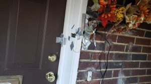
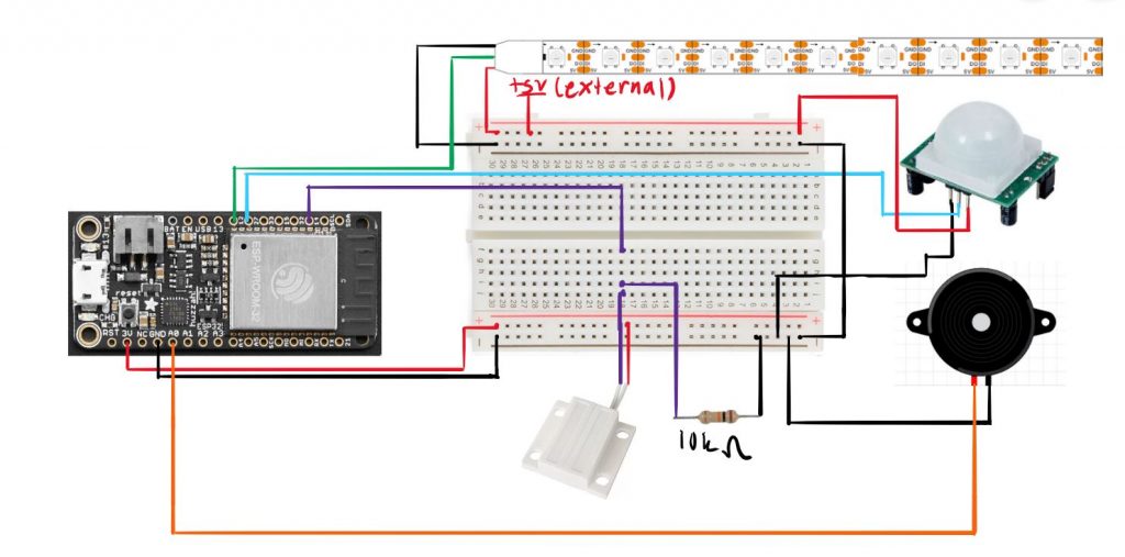
 In the final version, a rechargeable 9V battery would be stepped down to 5V would power the LED strip and PIR motion sensor rather than my uno plugged into my laptop which I used because my 9V battery was drained. Using a usb wall plug, I would power the esp32 board rather than my laptop’s port. The outlet my laptop is plugged into would be used for this.
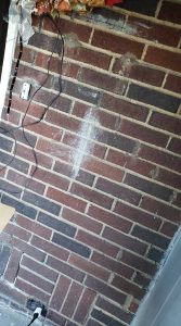
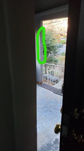 I would run the LED strip wires across the roof of the porch and put the LED strip where the green circle is. This way, it would be where you face while leaving the house and is in the line of sight for going down the porch stairs.