Problem:
There are many factors that have to be considered in managing risk of contagion during the pandemic. These are not straightforward, and can vary wildly depending on the context and combination of variables. Constantly trying to analyze these can cause fatigue, anxiety and unnecessary worry about perceived risks.
One particularly difficult element to get a good gauge on whether it is safe to remain indoors in a particular space. While maintaining 6ft of distance is still a good rule of thumb, it doesn’t always guarantee low risk.
This can be counterbalanced by other risk factors, such as ventilation and speaking volume. Risky activity such as singing generates significantly more droplets and aerosols that increases infection risks significantly, even when keeping a distance of 6ft.
Often, in an enclosed space, even when in individuals are in close proximity, a powerful HVAC system is circulating the air can prevent significant spreading. For example, when looking at transmission patterns in airplanes, only a few individuals sitting directly next to, in front of and behind Patient Zero were infected. Others remained safe, even though they remained in the same (relatively small) enclosed area for a significant amount of time.
This further complicated by having to consider the volume of indoor space – how risky these factors are varies considerably based on that as well.
Without ventilation, aerosols remain suspended in the air, becoming increasingly concentrated as time goes by. (Source)
Solution:
Lots of these factors, such as ventilation and speaking volume, are invisible and hard to keep track to begin with. Compared to distance from the next person, it’s really difficult for the average person to estimate what’s safe and what’s not.
It is even more challenging and stressful to calibrate these against dynamic changes from people coming and leaving, and the type of activity or behavior they choose when in said space.
By developing a system that balances all these factors and aggregates an overall risk grade that is displayed in a public space, it’s much easier for incoming and outgoing individuals to gauge their risk and exposure, and take the necessary precautions immediately.
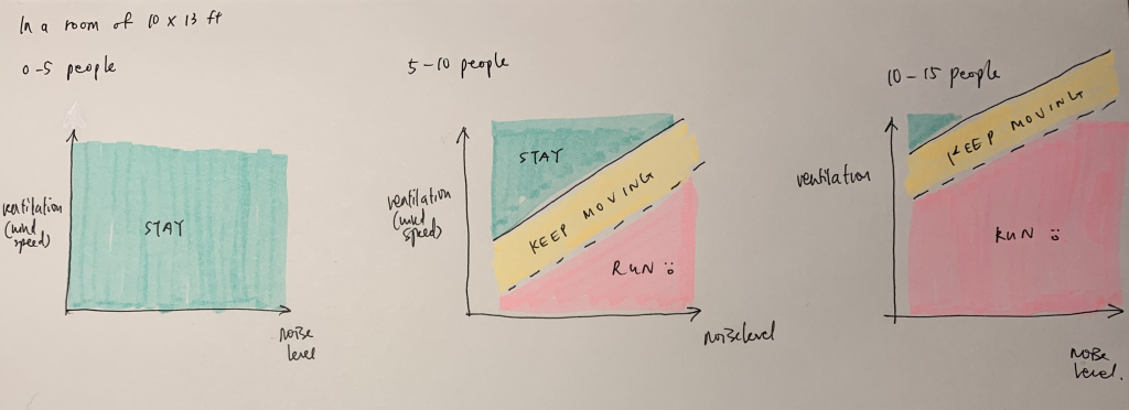
As the number of people increase, the tradeoff between ventilation and noise level changes. We monitor these different axes with a wind sensor, a sound sensor and an ultrasonic sensor.
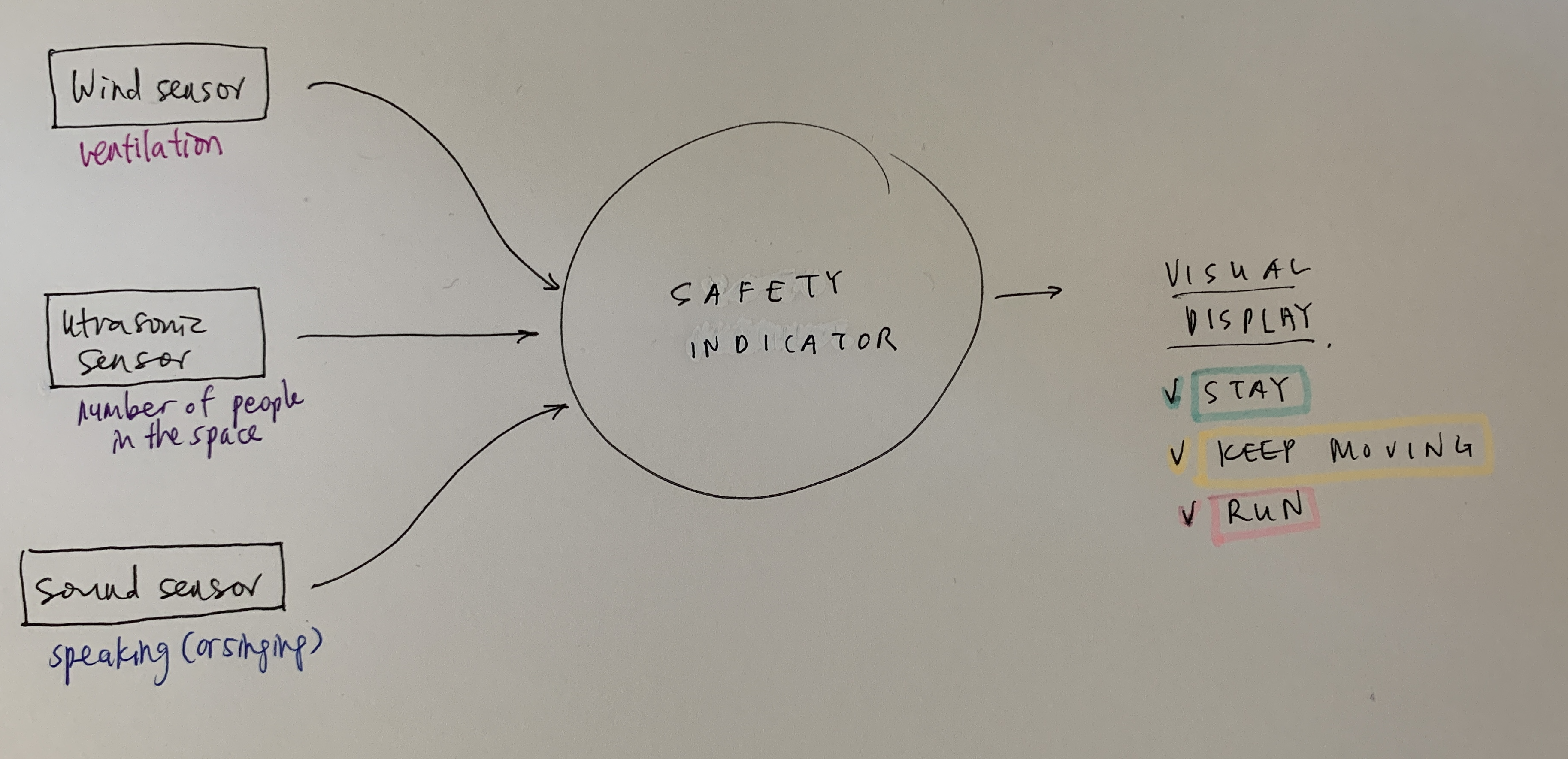
Components:
- 1x HC-SR04 ultrasonic sensor
- 1x RGB Diffused Common Cathode
- 3x LED (Red, Green, Yellow)
- 6x Resistor 220 ohm
- Wind Sensor Rev. C
- 1x LCD1602 Module
- Sound sensor (replaced by potentiometer)
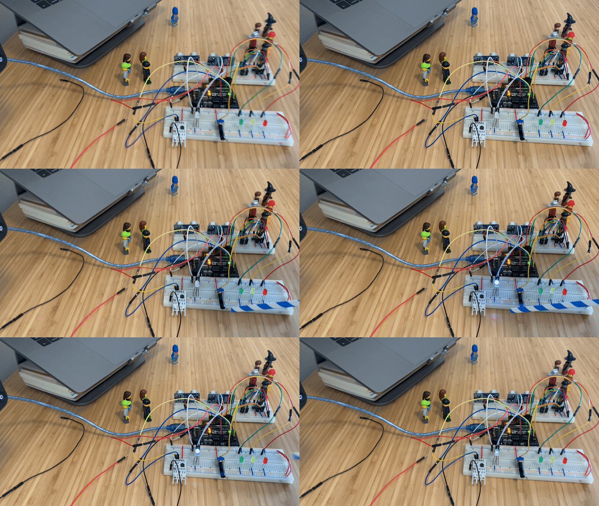
Wind sensor
The wind sensor gives us an approximation of the rate of airflow, and thus some insight into the amount of ventilation that a space has.
Ultrasonic sensor
Using two ultrasonic sensors, we can keep count of how many people are in the room at any one time.
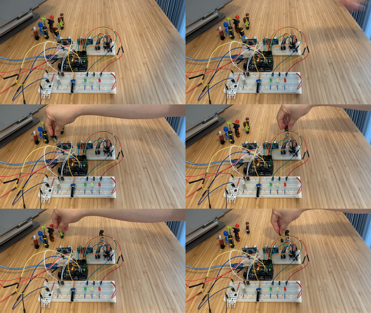
Sound sensor
The decibel level can give us an approximation of how loudly people in the room are speaking (and thus how likely they are to expel aerosols in the air). A library is ~40dB, and a cafe is ~80dB. I will be substituting this value with a potentiometer for demo purposes, with a range of 1-100 to represent dB levels.
Safety rating
Keeping track of all this and displaying this information to the individuals in a space is an overall safety rating that indicates the recommended course of action to remain safe.
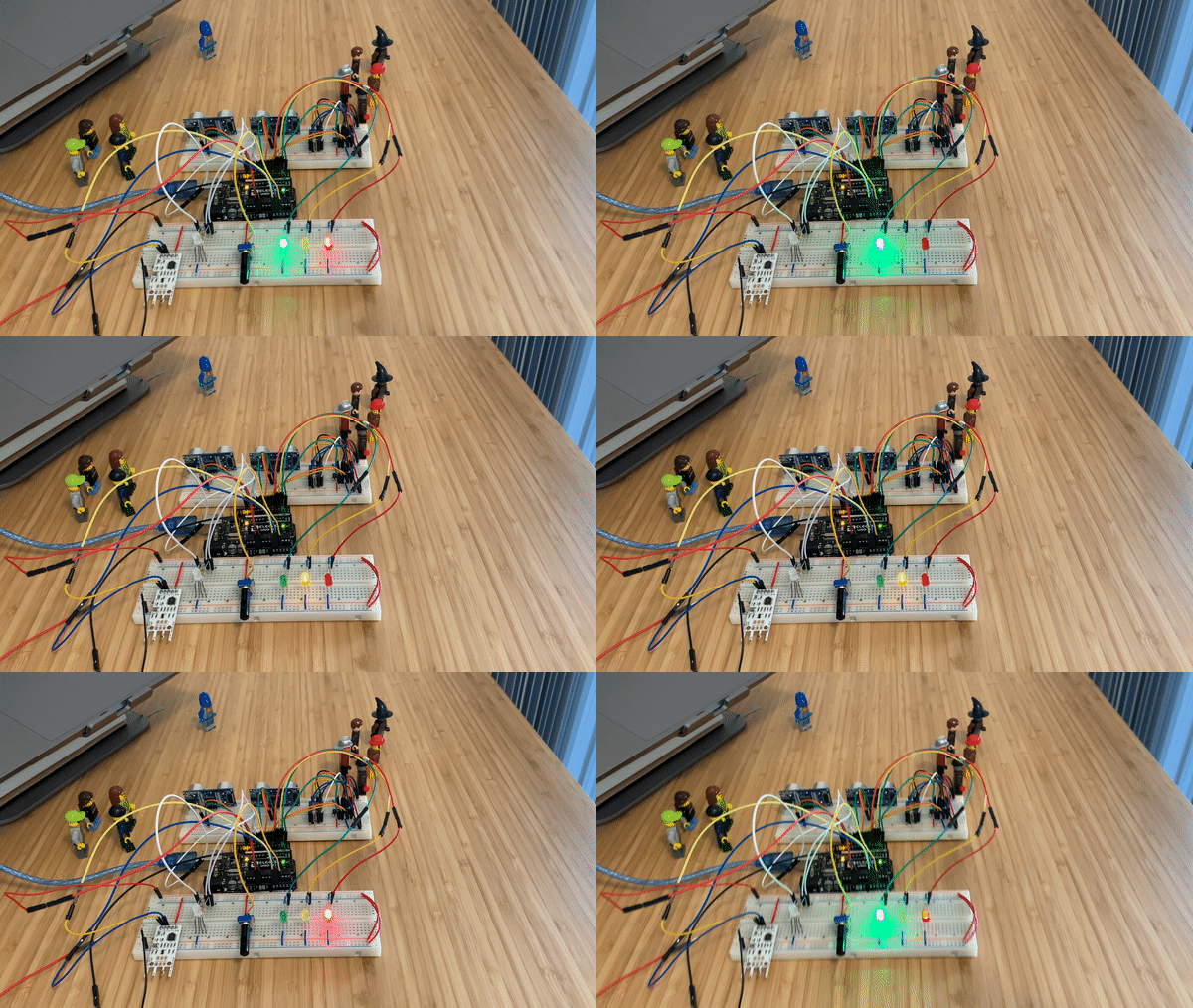
What should you do, and when?
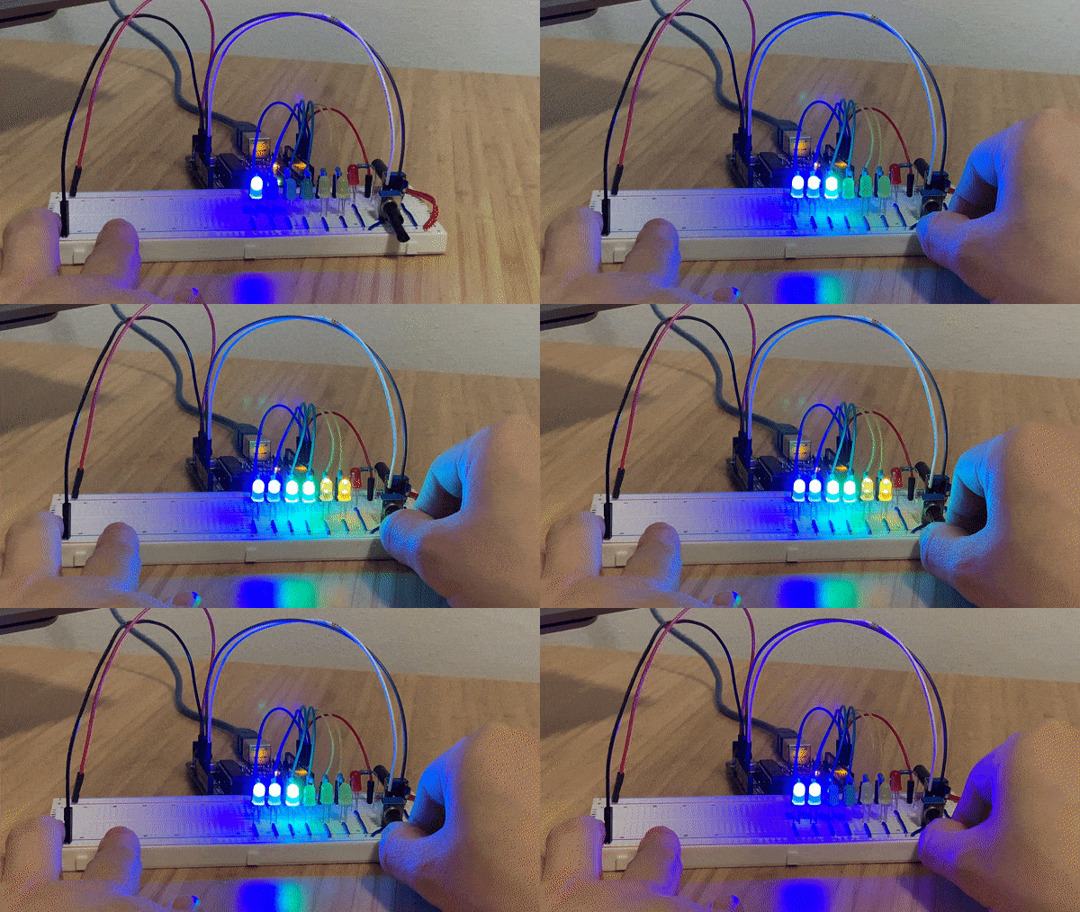
When the number of people in a room is small, the safety rating remains green regardless of how well ventilated and how loud people are.
But, if enough people gather, the safety rating will turn red.
In this case, you might choose not to enter the room, and keep walking. If you do need to be present, there are a few things you can do to improve the situation.
Reducing speaking levels and ventilation levels can shift the safety ratings. Depending on the extent of how much each of these fluctuate and in what direction, the overall effect could be either an increase or decrease in risk levels.
Another way to improve the safety rating is to just decrease the total number of people in a space.
If the safety rating does not change after making these adjustments, it’s a sign that you should leave in order to be safe.
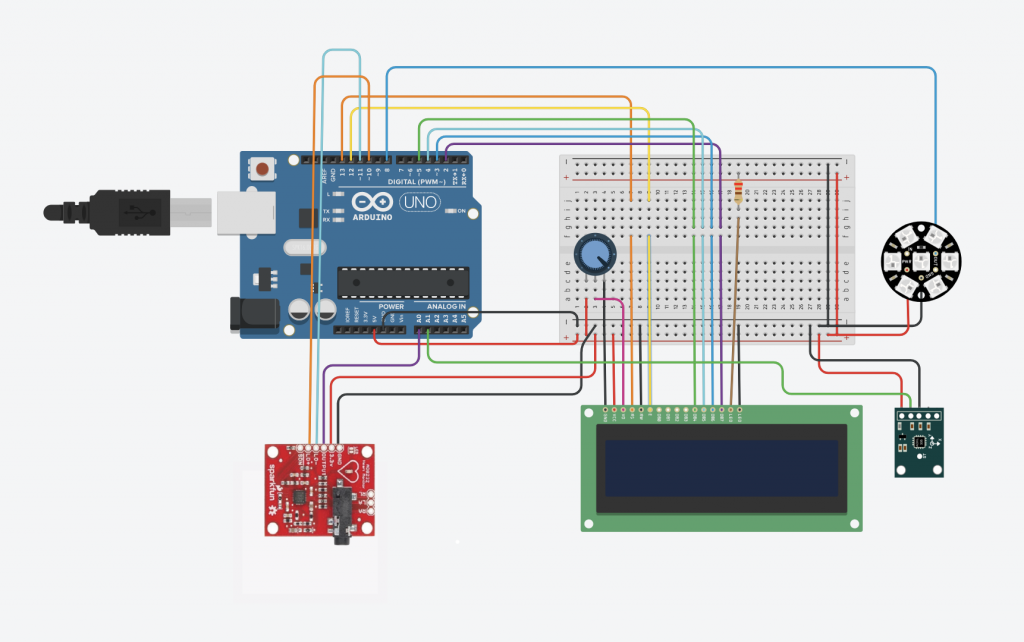
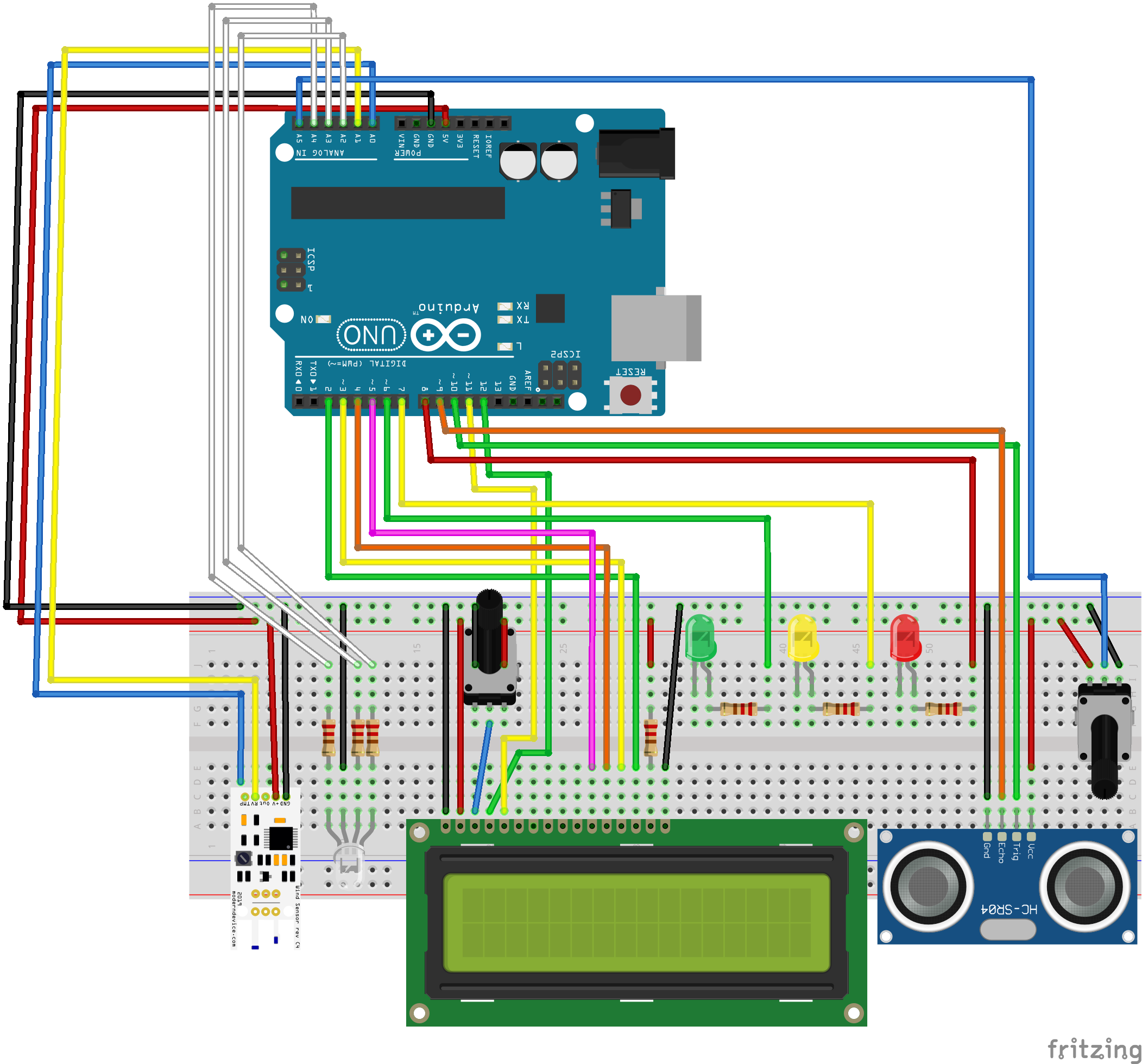
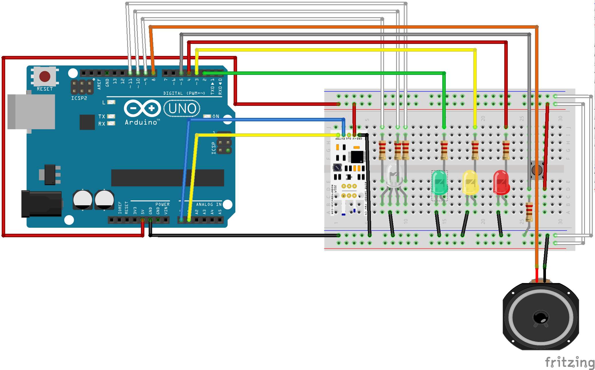
Schematic:
Code:
/*************************************************
* Ultrasonic sensor + LCD screen
*************************************************/
#include <Wire.h>
#include <LiquidCrystal.h>
LiquidCrystal lcd(12, 11, 5, 4, 3, 2);
#define trigPin 10
#define echoPin 9

int counter = 0;
int currentState1 = 0;
int previousState1 = 0;
int currentState2 = 0;
int previousState2 = 0;
int inside = 0;
int outside = 0;

/*************************************************
* Wind Sensor
*************************************************/
#define analogPinForRV    1   // blue jumper wire
#define analogPinForTMP   0   // yellow jumper wire

// to calibrate your sensor, put a glass over it, but the sensor should not be
// touching the desktop surface however.
// adjust the zeroWindAdjustment until your sensor reads about zero with the glass over it.

const float zeroWindAdjustment =  .2; // negative numbers yield smaller wind speeds and vice versa.

int TMP_Therm_ADunits;  //temp termistor value from wind sensor
float RV_Wind_ADunits;    //RV output from wind sensor
float RV_Wind_Volts;
unsigned long lastMillis;
int TempCtimes100;
float zeroWind_ADunits;
float zeroWind_volts;
float WindSpeed_MPH;

//LED Feedback
int redPin = A4; //Pin for the red RGB led pin
int greenPin = A3; //Pin for the green RGB led pin
int bluePin = A2; //Pin for the blue RGB led pin

int writeValue_red; //declare variable to send to the red LED
int writeValue_green; //declare variable to send to the green LED
int writeValue_blue; //declare variable to send to the blue LED


/*************************************************
* Sound sensor
*************************************************/
#define soundSensorPin  5
int soundSensor = 0;
bool soundRisk = false;

/*************************************************
* Aggregated risk
*************************************************/
int riskLevel = 0;
int greenLED = 6;
int yellowLED = 7;
int redLED = 8;

/*************************************************
 *
 * SETUP
 *
*************************************************/

void setup(){
  Serial.begin (57600);

  //Ultrasonic sensor + LCD
  pinMode(trigPin, OUTPUT);
  pinMode(echoPin, INPUT);
  lcd.begin(16,2);

  //wind sensor
  Serial.println("start");
  //   Uncomment the three lines below to reset the analog pins A2 & A3
  //   This is code from the Modern Device temp sensor (not required)
  pinMode(A2, INPUT);        // GND pin
  pinMode(A3, INPUT);        // VCC pin
  digitalWrite(A3, LOW);     // turn off pullups

  //Risk feedback state
  int greenLED = 6;
  int yellowLED = 7;
  int redLED = 8;
  pinMode(greenLED, OUTPUT);
  pinMode(yellowLED, OUTPUT);
  pinMode(redLED, OUTPUT);

}

void loop(){

/*************************************************
* Ultrasonic sensor + LCD screen
*************************************************/
//setting up LCD screen display
lcd.setCursor(0, 0);
lcd.print("IN: ");
lcd.setCursor(7, 0);
lcd.print("Wind: ");
lcd.setCursor(0, 1);
lcd.print("OUT: ");
lcd.setCursor(7, 1);
lcd.print("Total: ");

//sending ping + calculating distance using ultrasonic sensor
long duration;
float distance;
digitalWrite(trigPin, LOW);
delayMicroseconds(2);
digitalWrite(trigPin, HIGH);
delayMicroseconds(10);
digitalWrite(trigPin, LOW);
duration = pulseIn(echoPin, HIGH);
distance = (duration/2) / 29.1;

//going inside
if (distance<= 9){
  currentState1 = 1;
}
else {
  currentState1 = 0;
}

delay(100);

if(currentState1 != previousState1){
  if(currentState1 == 1){
    counter = counter + 1;
    inside = inside + 1;
    //update LCD screen
    lcd.setCursor(14, 1);
    lcd.print(counter);
    lcd.setCursor(4, 0);
    lcd.print(inside);
  }
  }

//returning outside
  if (distance > 14 && distance <=30){
    currentState2 = 1;
  }
  else {
    currentState2 = 0;
  }
  delay(100);

  if(currentState2 != previousState2){
    if(currentState2 == 1){
      counter = counter - 1;
      outside = outside + 1;
      //update LCD screen
      lcd.setCursor(14, 1);
      lcd.print(counter);
      lcd.setCursor(5, 1);
      lcd.print(outside);
    }
  }

//keeping tally based on
    Serial.print("   IN:");
    Serial.println((float)inside);

    Serial.print("   OUT:");
    Serial.println((float)outside);

    Serial.print("   TOTAL INSIDE:");
    Serial.println((float)counter);

//debugging
//    Serial.println(duration);
//    Serial.println(duration/2);
//    Serial.println((duration/2) / 29.1);


/*************************************************
* Wind Sensor
*************************************************/
  if (millis() - lastMillis > 200){      // read every 200 ms - printing slows this down further

    TMP_Therm_ADunits = analogRead(analogPinForTMP);
    RV_Wind_ADunits = analogRead(analogPinForRV);
    RV_Wind_Volts = (RV_Wind_ADunits *  0.0048828125);

    // these are all derived from regressions from raw data as such they depend on a lot of experimental factors
    // such as accuracy of temp sensors, and voltage at the actual wind sensor, (wire losses) which were unaccouted for.
    TempCtimes100 = (0.005 *((float)TMP_Therm_ADunits * (float)TMP_Therm_ADunits)) - (16.862 * (float)TMP_Therm_ADunits) + 9075.4;

    zeroWind_ADunits = -0.0006*((float)TMP_Therm_ADunits * (float)TMP_Therm_ADunits) + 1.0727 * (float)TMP_Therm_ADunits + 47.172;  //  13.0C  553  482.39

    zeroWind_volts = (zeroWind_ADunits * 0.0048828125) - zeroWindAdjustment;

    // This from a regression from data in the form of
    // Vraw = V0 + b * WindSpeed ^ c
    // V0 is zero wind at a particular temperature
    // The constants b and c were determined by some Excel wrangling with the solver.

   WindSpeed_MPH =  pow(((RV_Wind_Volts - zeroWind_volts) /.2300) , 2.7265);


//debugging
//    Serial.print("  TMP volts ");
//    Serial.print(TMP_Therm_ADunits * 0.0048828125);
//
//    Serial.print(" RV volts ");
//    Serial.print((float)RV_Wind_Volts);
//
//    Serial.print("\t  TempC*100 ");
//    Serial.print(TempCtimes100 );
//
//    Serial.print("   ZeroWind volts ");
//    Serial.print(zeroWind_volts);

    Serial.print("   WindSpeed MPH ");
    Serial.println((float)WindSpeed_MPH);

    lastMillis = millis();

    lcd.setCursor(13, 0);
    lcd.print(WindSpeed_MPH);
  }

/*************************************************
* Wind sensor LED feedback
*************************************************/

  writeValue_red = (255./10.)*WindSpeed_MPH; //Calculate the value to write on the red LED (add point to change to float point)
  writeValue_green = (255./10.)*WindSpeed_MPH; //Calculate the value to write on the green LED
  writeValue_blue = (255./10.)*WindSpeed_MPH; ///Calculate the value to write on the blue LED

  analogWrite(redPin,writeValue_red); //write value to set the brightness of the red LED
  analogWrite(greenPin,writeValue_green); //write value to set the brightness of the green LED
  analogWrite(bluePin,writeValue_blue); //write value to set the brightness of the blue LED


/*************************************************
* Sound sensor
*************************************************/
int soundSensor = analogRead(soundSensorPin);

//assuming that there are two main buckets of sound levels - one is low, which conversational and not risky, and the other is high, such as singing, which is risky)
if (soundSensor >= 100){
  soundRisk = true;
}
  else {
    soundRisk = false;
  }

Serial.println(soundSensor);
Serial.println(soundRisk);

/*************************************************
* States + risk level display
*************************************************/

//small group
if (counter <= 3) {
  //sound and ventilation doesn't matter
  riskLevel = 0;
}

//medium group
else if (counter > 3 && counter <=5){
  //sound risk is high, ventilation needs to be high
  if (soundRisk == true){
    if (WindSpeed_MPH >= 10){
      riskLevel = 0;
    } else if (WindSpeed_MPH < 10 && WindSpeed_MPH >= 7){
      riskLevel = 1;
    } else if (WindSpeed_MPH < 7){
      riskLevel = 2;
    }

  //sound risk is low, ventilation can be lower
  } else if (soundRisk == false){
      if (WindSpeed_MPH >= 7){
        riskLevel = 0;
      } else if (WindSpeed_MPH < 7 && WindSpeed_MPH >=2){
        riskLevel = 1;
      } else if (WindSpeed_MPH < 2){
        riskLevel = 2;
      }
  }

  //
}

//big group
else if (counter > 5){
  //sound risk is high, ventilation needs to be high
  if (soundRisk == true){
    if (WindSpeed_MPH >= 20){
      riskLevel = 0;
    }
    if (WindSpeed_MPH >= 10 && WindSpeed_MPH < 20){
      riskLevel = 1;
    } else if (WindSpeed_MPH <10){
      riskLevel = 2;
    }
  //sound risk is low, ventilation can be lower
  } else if (soundRisk == false){
    if (WindSpeed_MPH >= 12){
      riskLevel = 0;
    } else if (WindSpeed_MPH >= 8 && WindSpeed_MPH > 5){
      riskLevel = 1;
    } else if (WindSpeed_MPH <= 5){
      riskLevel = 2;
    }
  }
}

/*************************************************
* Overall risk level display
*************************************************/

if (riskLevel == 0){
  //Low risk
  //turn green LED on
  digitalWrite(greenLED, HIGH);
  //turn the rest off
  digitalWrite(redLED, LOW);
  digitalWrite(yellowLED, LOW);
}

else if (riskLevel == 1){
  //Medium risk
  //turn yellow LED on
  digitalWrite(yellowLED, HIGH);
  //turn the rest off
  digitalWrite(redLED, LOW);
  digitalWrite(greenLED, LOW);
}

else if (riskLevel == 2){
  //High risk
  //turn red LED on
  digitalWrite(redLED, HIGH);
  //turn the rest off
  digitalWrite(yellowLED, LOW);
  digitalWrite(greenLED, LOW);
}

}
Reflections on implementation
There are a few things which I tried and did not turn out so well for the prototype. For starters, I had initially attempted to operationalize the graph diagram I had drawn earlier indicating the relationship between sound volumes and ventilations. Not only were the resultant numbers difficult to predict and thus challenging to show in a demo, sound generally clusters around two median values – loud, or not too loud. Instead of a continuous range, I went ahead and made the sound value a boolean instead. Actual implementation of this would also require a much more nuanced look at the relationship between these variables as well as the risk tradeoffs along a continuum, unlike the buckets that I had created to assist accuracy in the demo.
There were also some unpredictability in the ultrasonic sensor’s readings and counting of people – on occasion, it would double or even triple count, while on others it missed it totally. This challenged the reproducibility of the demo. If this were to be implemented in real life, much more robust software would be needed in order to provide an accurate estimate of the number of people in the room.
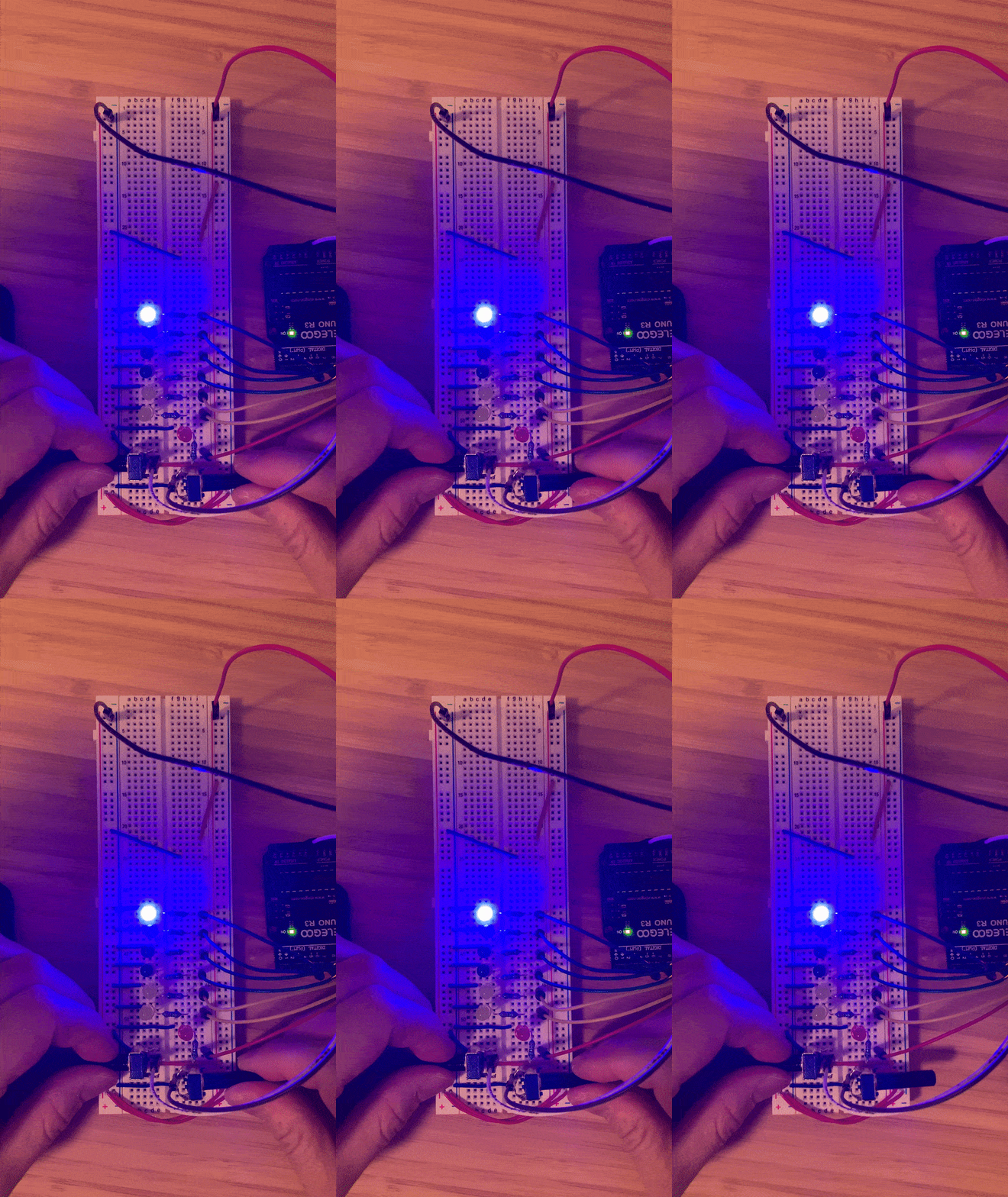
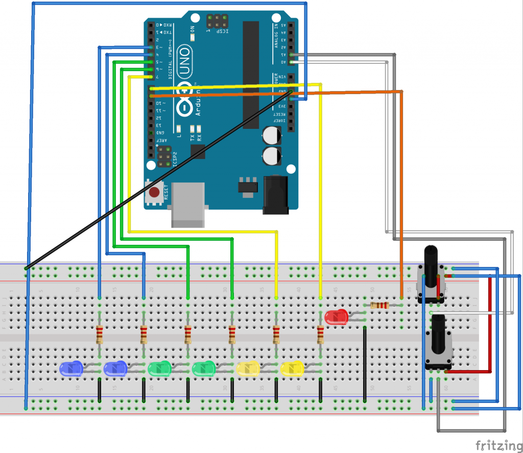
I’m glad that in my second iteration of the circuits and code I was able to fit everything onto a single breadboard, as it made it much easier to see what was happening or changing altogether at once.
Growing this project further
If I had had more time, I would have liked to delve more into strategies in responsive architecture to help individuals respond more appropriately to the risk level. For example, if this was a public area such as an indoor mall, perhaps public seating can transform to become more hostile to discourage loitering, or eliminate it by disappearing altogether.
One can imagine the benches shape-shifting into something uncomfortable. The example below illustrates this in action:
Or, they could disappear altogether into the ground until it is safe again, like the night time urinals in London.
Other ways we could encourage individuals to cut their time in a space short is to switch off alternate lights, and/or cut off background music to give people the message to conclude their affairs quickly and leave as it feels like things are closing.
If it is able to be actuated, the building could also enforce a base-level of ventilation by automatically switching on the fans and opening the windows when the safety indicator goes yellow or red. Throwing open the windows when necessary would also also inevitably expose individuals to the elements of nature, encouraging them to disperse and head home, particularly in wintertime.



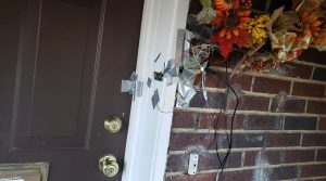
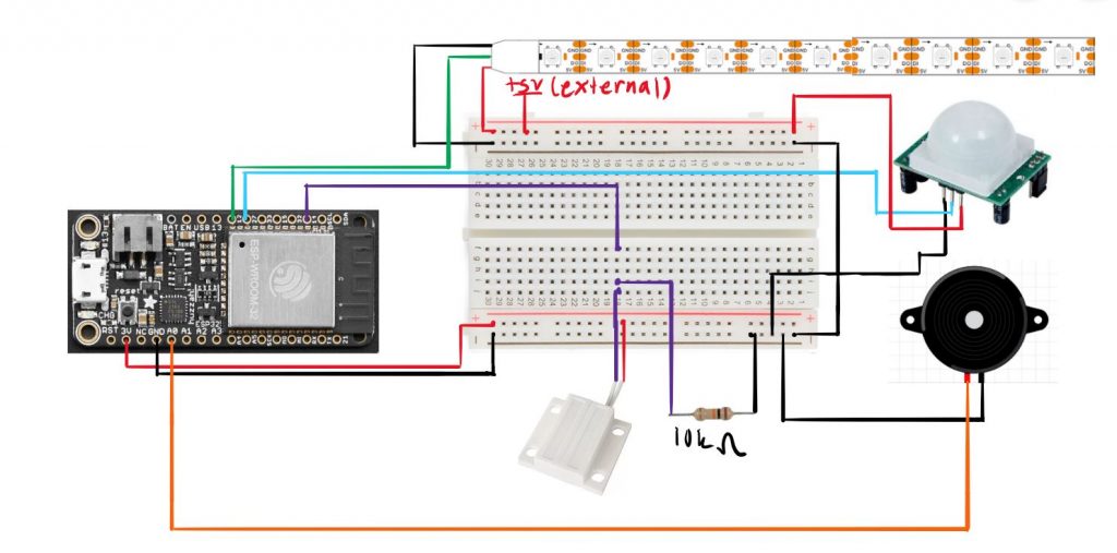
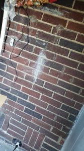 In the final version, a rechargeable 9V battery would be stepped down to 5V would power the LED strip and PIR motion sensor rather than my uno plugged into my laptop which I used because my 9V battery was drained. Using a usb wall plug, I would power the esp32 board rather than my laptop’s port. The outlet my laptop is plugged into would be used for this.
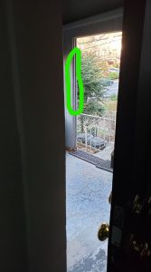 I would run the LED strip wires across the roof of the porch and put the LED strip where the green circle is. This way, it would be where you face while leaving the house and is in the line of sight for going down the porch stairs.