Sensing glove for Scuba Divers

Problem

Diving is an exciting and enjoyable sport. However, it can also be dangerous if the divers are not ware of the condition of their equipment, their companions, and the environment. Most divers are trained to understand their equipment well, but it is still difficult to keep track of one’s diving buddies and the environment even for experienced divers. It becomes quite difficult to keep track of others when a diving group has 3 people, and it is difficult to know one’s surrounding when the visibility is low in a cave or at night. Most of the time, the divers have to focus on what is ahead of them. Frequent checking around for people and surrounding would slow down the movement and distract the divers.

Solution

I previously saw that LED fibers are now integrated into some designs of the cloths. Therefore, I have this idea that a glove with LED on the back can be used as a sensing/locating system to tell the divers the positions of their companions of whether there is a rock or hard surface behind them. The idea is that The diver will wear 4 ultrasonic ranger for the front, back, left, and right. When the sensor detects objects in a certain range, a signal will be sent to the glove and shown as a light-up LED.
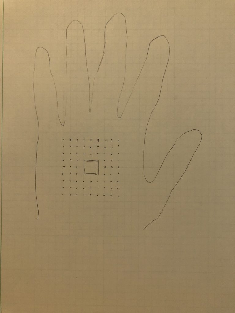
The sensing glove

With the information shown on the divers’ glove, they no longer need to look back or around to check on the situation. More importantly, this will be very useful during night dive when the only visible area is 2-4 m pointed by the flashlight.

Proof of Concept

Because of the lack of materials, I only use 1 ultrasonic sensor to stimulate the function of one of the four ultrasonic sensor. I originally planned to use a LED matrix as it is more accurate to the original design. But LEDs were used instead because I cannot get one of the LED matrix. The LEDs represent the angle or direction of the detected object, with the bottom LED being 0-30 degree and the top LED being 150-180 degree. Ideally, the distance is reflected by the distance of the light-up LED from the center block. The servo motor is used to rotate the ultrasonic sensor so that objects from a wider range of angles can be detected.
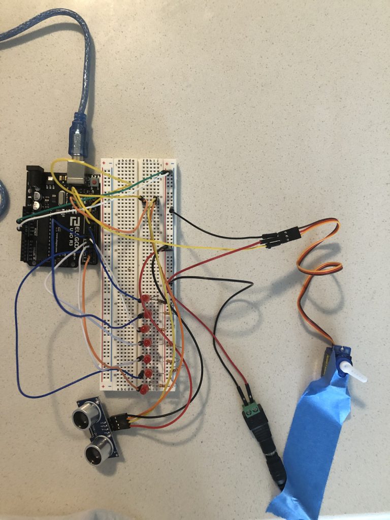
The set up of the hardware

Turning sensor

I used my hand to hold the ultrasonic sensor for the stimulation because the jumpers on the sensor stop the servo motor from moving freely. I tried to mimic the rotation made by the servo motor, but error still occurs as my hand cannot synchronize perfectly with the servo motor .
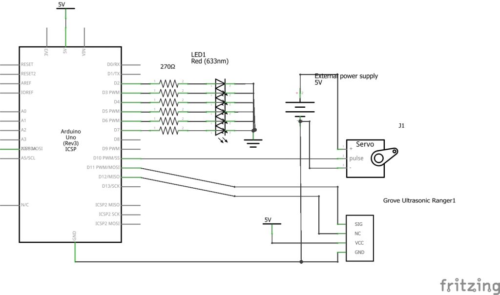
Demo of the device

Code:

#include <NewPing.h>
#include <Servo.h>

#define TRIGGER_PIN  12  // Arduino pin tied to trigger pin on the ultrasonic sensor.
#define ECHO_PIN     11  // Arduino pin tied to echo pin on the ultrasonic sensor.
#define MAX_DISTANCE 100 // Maximum distance we want to ping for (in centimeters). Maximum sensor distance is rated at 400-500cm.
#define SERVO_PIN 10
#define LED_0  2
#define LED_30  3
#define LED_60  4
#define LED_90  5
#define LED_120  6
#define LED_150  7


NewPing Sonar_1(TRIGGER_PIN, ECHO_PIN, MAX_DISTANCE); // NewPing setup of pins and maximum distance.

Servo Servo1; // you can call the servo whatever you want

//Timer
//Clock 1 is the timer for the servo
unsigned long clock1 = 0; // variable for timing
const int INTERVAL1 = 5; // milliseconds between updates

//Global variables
int angle;
bool bounce = true;

int direc_distance[181];
int angle_of_objects[10];

//Functions
//Sweeping the servo motor
void sweep_servo() {
  if (bounce == true) {
    angle = angle + 1;
    Servo1.write(angle);

    dir_dis(angle);

    if (angle == 180) {
      bounce = false;

      clear_position();


      //Serial.print("0-180: ");
      check_position();


      Serial.println(angle_of_objects[0]);
      //Serial.println(angle_of_objects[1]);
      show_position();


    }
    return;
  }

  if (bounce == false) {
    angle = angle - 1;
    Servo1.write(angle);
    dir_dis(angle);

    if (angle == 0) {
      bounce = true;
      clear_position();

      //Serial.print("180-0: ");
      check_position();

      Serial.println(angle_of_objects[0]);
      //Serial.println(angle_of_objects[1]);

      show_position();


    }

  }


}

//The function that records the angle and the distance to the array direc_distance
void dir_dis (int angle) {

  direc_distance[angle] = Sonar_1.ping_cm();
}

void check_position() {
  //The for loop to find the angles of the locations of the objects

  int index;
  //Serial.print(direc_distance[0]);
  for (int i; i < 181; i++) {
    int start_angle;
    int end_angle;
    int mid_angle;

    if (direc_distance[i] != 0) {
      start_angle = i;

      //Serial.print(i);
      //Serial.print(",start angle:");

      while (direc_distance[i] != 0 and abs(direc_distance[i + 1] - direc_distance[i]) < 20) {
        i = i + 1;
        //Serial.println(direc_distance[i]);
        if (i == 180) {
          break;
        }
      }
      end_angle = i;

      mid_angle = (end_angle - start_angle) / 2;


      //Serial.println(start_angle);
      //Serial.print(",end angle:");
      //Serial.print(end_angle);
      //Serial.print(",mid angle:");
      //Serial.println(mid_angle);

      //Serial.print("This is mid angle:");
      //Serial.println(mid_angle);
      angle_of_objects[index] = mid_angle;
      if (index = 9) {
        return;
      }
      index = index + 1;
    }

  }
}

void light_LED(int angle) {
  if (angle == 0) {
    digitalWrite(LED_0, HIGH);
  }

  if (angle == 30) {
    digitalWrite(LED_30, HIGH);
  }

  if (angle == 60) {
    digitalWrite(LED_60, HIGH);
  }

  if (angle == 90) {
    digitalWrite(LED_90, HIGH);
  }

  if (angle == 120) {
    digitalWrite(LED_120, HIGH);
  }

  if (angle == 150) {
    digitalWrite(LED_150, HIGH);
  }


}

int select_angle(int angle) {
  if (angle < 30) {
    return 0;
  }

  if (angle >= 30 and angle < 60) {
    return 30;
  }


  if (angle >= 60 and angle < 90) {
    return 60;
  }

  if (angle >= 90 and angle < 120) {
    return 90;
  }

  if (angle >= 120 and angle < 150) {
    return 120;
  }

  if (angle >= 150 and angle < 180) {
    return 150;
  }
}


void show_position() {
  //Turns off all the LED lights
  digitalWrite(LED_0, LOW);
  digitalWrite(LED_30, LOW);
  digitalWrite(LED_60, LOW);
  digitalWrite(LED_90, LOW);
  digitalWrite(LED_120, LOW);
  digitalWrite(LED_150, LOW);


  int angles[] = {0, 30, 60, 90, 120, 150, 180};

  for (int i; i < 10; i++) {
    if (angle_of_objects[i] == 0) {
      Serial.println("Done");
      return;
    }


    int angle_light = select_angle(angle_of_objects[i]);


    Serial.println(angle_light);
    light_LED(angle_light);
  }
}

//This function clears the stored angles of the positions of the objects
void clear_position() {
  for (int i; i < 10; i++) {
    angle_of_objects[i] = 0;
  }
}

void setup() {
  pinMode(LED_0, OUTPUT);
  pinMode(LED_30, OUTPUT);
  pinMode(LED_60, OUTPUT);
  pinMode(LED_90, OUTPUT);
  pinMode(LED_120, OUTPUT);
  pinMode(LED_150, OUTPUT);
 

  Servo1.attach(SERVO_PIN);

  Serial.begin(115200); // Open serial monitor at 115200 baud to see ping results.

  Servo1.write(0);
  //digitalWrite(LED_180, HIGH);
  delay(2000);


}

void loop() {


  //The servo clock
  if (millis() >=  clock1) {
    //decreases the minute value in the timer for each task
    sweep_servo();

    clock1 = millis() + INTERVAL1 ;

    //Serial.println(angle_of_objects[0]);


  }
}
 

Visual Timer

Problem

Time management is an important element in cooking. And it can get very difficult when there are multiple things that run spontaneously and need to be kept tracked of. Even through some cooking devices have their own timer, it is still difficult to pay attention to all of them once the there are multiple devices running. In addition, the devices are usually located differently across the kitchen.  Beeping sound is a great reminder, but it is difficult again if the person is deaf and cannot rely on sound.

Solution

One of the solutions is to “combine” the timers and put it into one device. Then, using accessible visual element to make the information comprehensive.

The components of the timer.

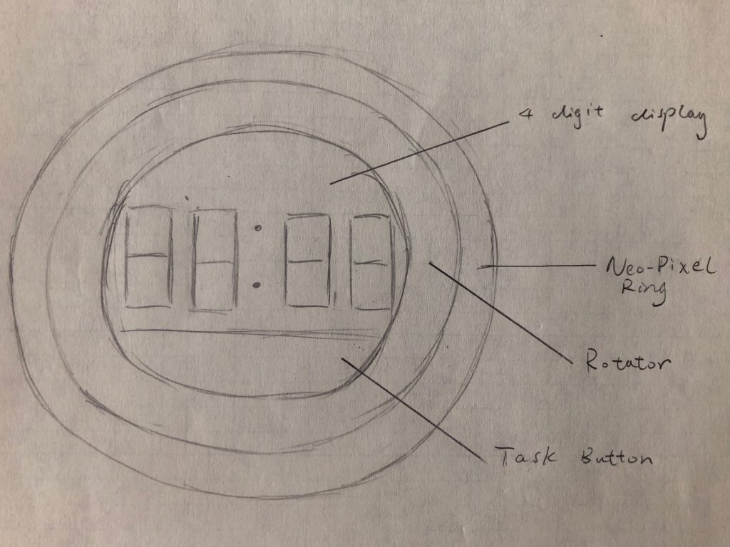
This is a timer made of a 4 digit display, a task button, a rotatory button, and a neo-pixel wheel. It is a device that keeps track of the remaining time of different tasks.  Push the task button to add a timer for a task. Rotate the rotary button to adjust how many hours and minutes the task will last. The new-pixel wheel will light up and reflect the length of the time.Push the rotary button to confirm the time.

Later, simply push the rotary button to go through the tasks and check the remaining time. Again, the neo-pixel wheel will reflect the percentage of time remaining.  Different tasks are indicated by the color shown on the neo-pixel wheel.

When one of the task is done, the new-pixel wheel will roll in circle as a reminder.

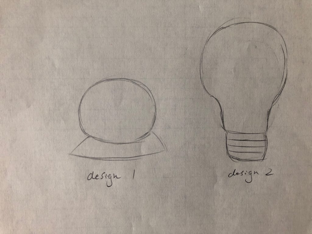
But only color is not enough to indicate which task is been done. Therefore, besides the timer device, different colors of LED lights are placed next to the task in the kitchen as a reminder. Such lights are turned on and off manually when the task starts and ends. I think keeping the manual part of control the light can give the user more awareness of the ongoing tasks. There are two designs of such lights. One can sticks to any surface, and one can only be mounted on a specific location like a light bulb. Design 1 offers more flexibility while design 2 is more durable if the tasks or cooking devices are fixed.

The LED lights

Proof of Concept

I made a prototype of the timer on a breadboard. The button on top is the rotary button. The potentiometer represents the turning of the rotary button. And the buttom button is the task button to add new task. The displayed number is a little inconsistent because the potentiometer does not fit well into the breadboard.

In the following videos, I first add a task with its time. I then add another task with another time. Finally, I check the remaining time of the two tasks. The pause before the display of the remaining time of the task is due to the code that run for the neo-pixel wheel which is not used in this prototype.

Thoughts on Making It So

After reading the forewords and the first chapter, I was amazed at first by the idea that we can learn design elements for real-world interface from interfaces in science-fiction and movies. But then as pointed out in the book, everything designers do before the product is manufactured falls into the realm of speculative fiction. Imagination drives the design, and real-world concern controls or withholds the possible and impossible so that the design is doable. I was amazed particularly about the Xenotran Mark II Dynamic Sand Table given as an example that lesson can be learned from X-man or science fiction. First of all, I did not know such a thing exist! A dynamic map that projects up-to-date satellite imagery developed in 2004! Secondly, this makes me rethink the relationship between technology and science fiction. I used to think that new technology is developed due to practical concern for the military, and the technology becomes mature and accessible when the cost falls. But that’s only half of the story, as the military does the same thing as the science fiction writers to find better solutions, only with more resources and commitment to develop the technology.

The best thing I learnt from chapter three is that boundaries of visual interface are wider than I thought. I used to focus more on the function or performance and consider visual interface rather as an mere aesthetic element. However, as shown through chapter three, the combination of elements such as text-based or graphic user interface, typography, color, transparency, and layers not only can convey a feeling for a specific time (futuristic, or a historical time period), but also affect the way users take in information. How to distribute (Overlaying? Spread out spatially?) and present(motion graphics? with glow>) the information has a powerful influence on the utility of the interface. In addition, it is so interesting that some of elements considered futuristic were originally used due to the technical difficulty. Some elements that stray away from the ordinary “future” may also be accepted as futuristic. It shows a dynamic relationships between technology, design, and culture.

Interactive Wall

Premise:

Even though the physical interaction between intelligent system and humans is advanced in the movie Blade Runner 2049, I did not like the austere apartment the protagonist lives in. It displays little interest in the comfort of the occupant with simple furniture and grey, industrial walls. The only meaningful interaction that occurs comes from JOI, the holographic artificial intelligent. This makes me wonder what things in our private space can bring comfort if interaction is introduced.

Nowadays people in the city live in dorms and apartments where physical space can be quite limited. Walls define the boundaries of our private space, but walls are never used as space themselves. It is used as a surface to hang or mount things. Therefore, I want to envision an interactive wall that can expand beyond physical space.

Hardware Setup:

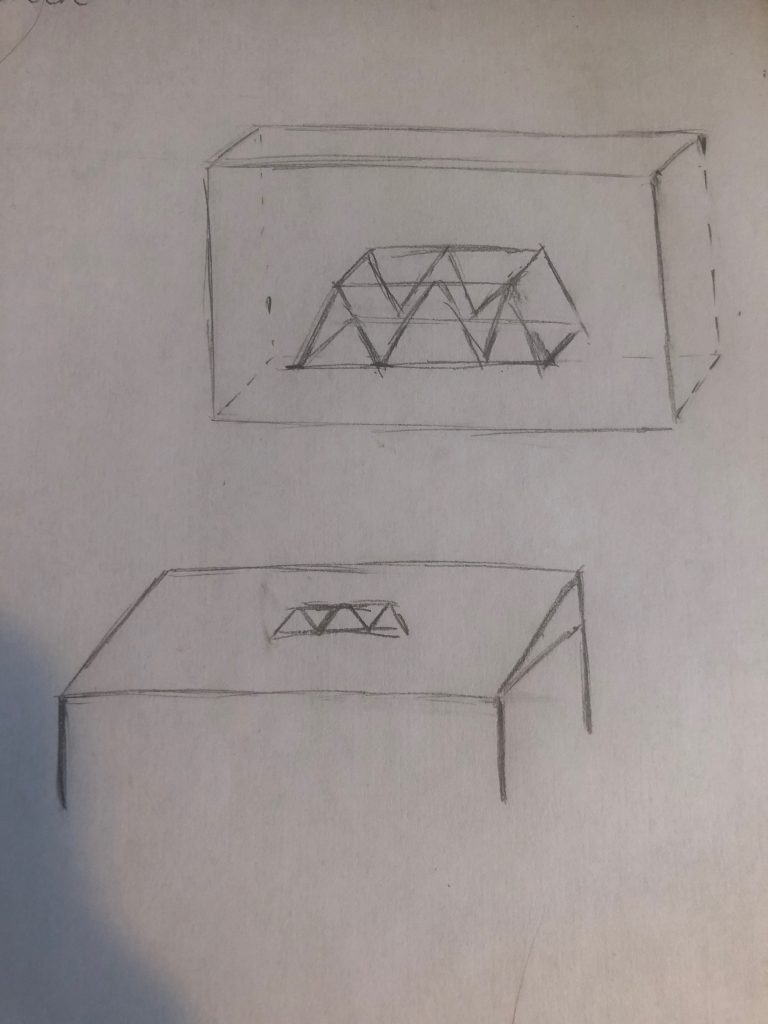
Depth is necessary to make use of the walls as space. “Holographic display” is still a developing technology but it will give walls the needed depth to create a visual space. Such walls can be used to change the environment of the space. For example, having bamboo around the room when having breakfast. And with a touch screen, such walls can also be used in many applications such as displaying and assembling 3D objects.

An interactive wall and a table with touch screen

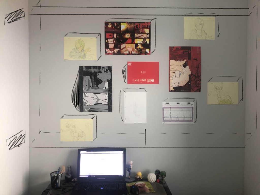
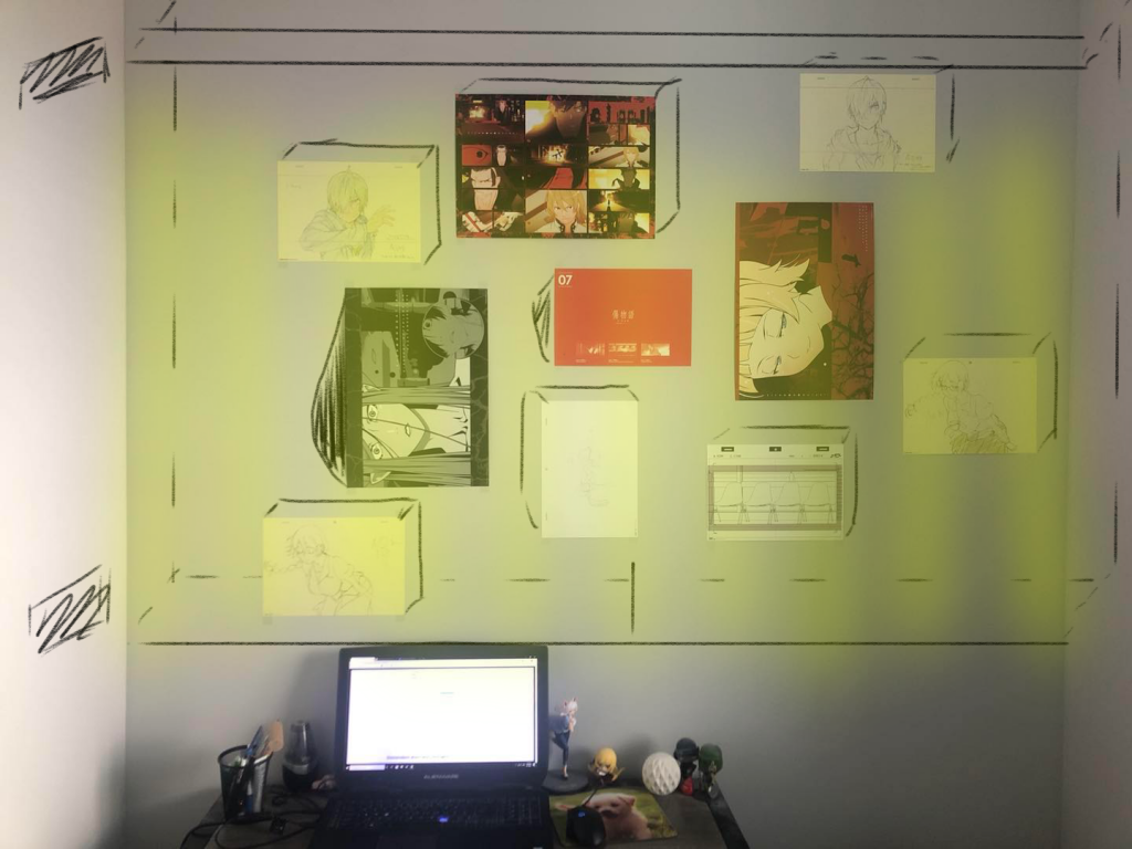
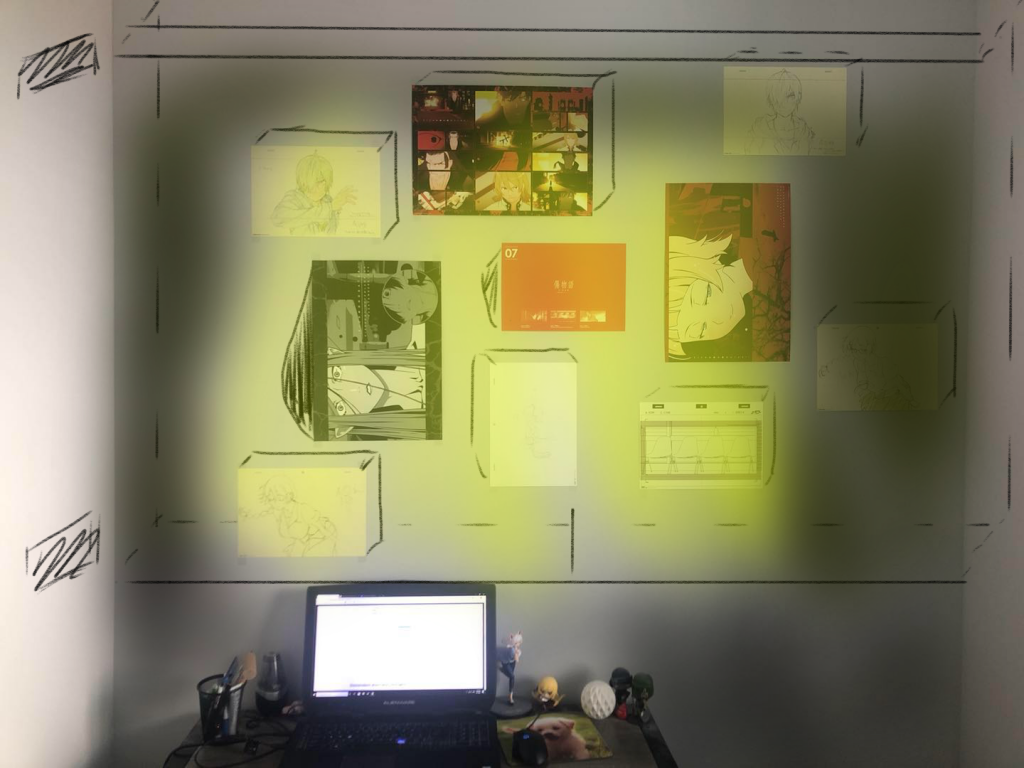
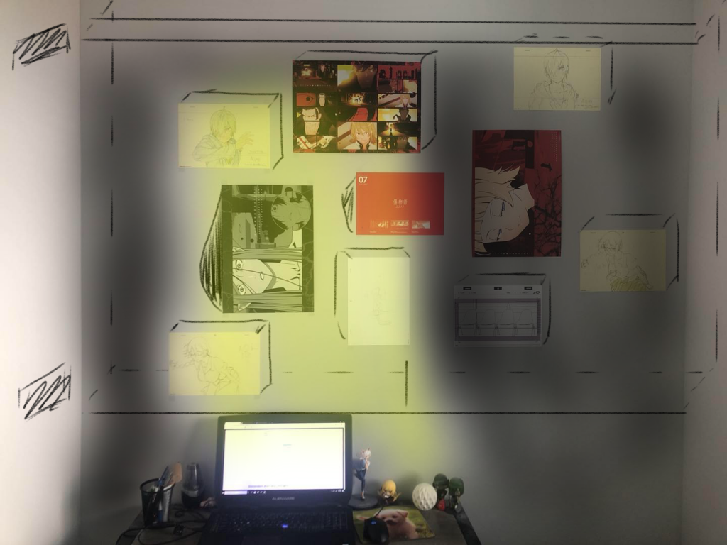
Lights and speakers can be incorporated into the wall to make it more interactive.  As shown in the picture below, there are two speakers on the left and lighting on the wall. Together they can create a corner or a space of cinematic experience.

Set up of the interactive wall

Interaction:

The wall can collect data on what the user like to display at different time of the day and week. Then like a smart “wallpaper engine”, it can change the environment of the room to fit the activity of the occupant. For example, once it “learns” that I like to look at bamboo and listen to birds’ tweets during breakfast, it shows a waterfall at the breakfast time the next day.

The wall can also be more engaged in the occupant’s living habit. I, for example, am often energetic during the night and I sometimes stay up until I realize there is not enough time to sleep. Or sometimes I did not realize that it is better to rest because my body is tired. With the active change of the range of light according to time in night, the wall is able to remind and urge me to rest. In similar way, the interactive wall can create a space that “synchronizes” with the occupant.

Lighting at 9 pm.
Lighting at 11 pm.
Lighting at 1 am.