Abstract
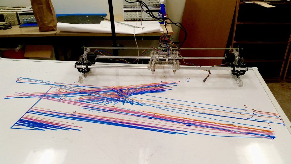
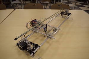
The AlgoBot is a wheeled robot that draws an algorithmic pattern with dry erase markers. The prototype is based on the design of an industrial CNC machine. Using a gantry system for movement in the x-direction and custom cut wheels for movement in the y-direction, the robot is capable of drawing any generated pattern. The gantry system and wheels are both driven by NEMA 17 stepper motors and the algorithmic patterns were generated using Processing. The structure can easily be scaled up to act as a custom flatbed printer that can draw on any surface.
Objective: Make a wheeled robot that draws an algorithmic pattern.
Related Work
Exploratorium Drawbot
A flat bed suspended from its corners by wire so that it can smoothly swing, and a single arm that firmly presses a marker on a sheet of paper (drawing as the bed oscillates).
Three-Pendulum Rotary Harmonograph
https://www.youtube.com/watch?v=HJYvc-ISrf8
A mechanical artifact that varies the frequency and phase of three pendulums to create different patterns.
Drawing Machine II
https://www.youtube.com/watch?v=BG9e06IWAxE
A stepper motor driven machine that creates complex guilloche patterns.
Implementation
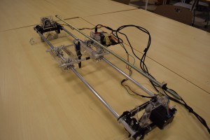
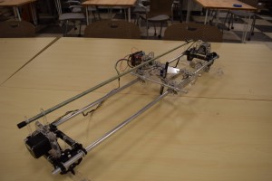
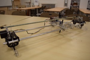
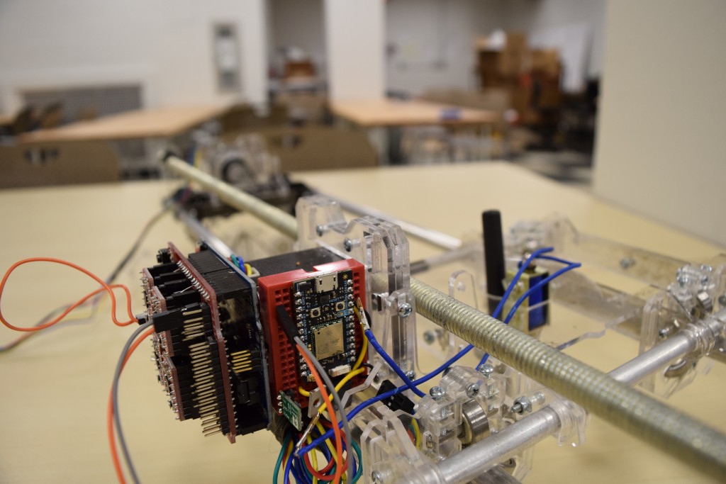
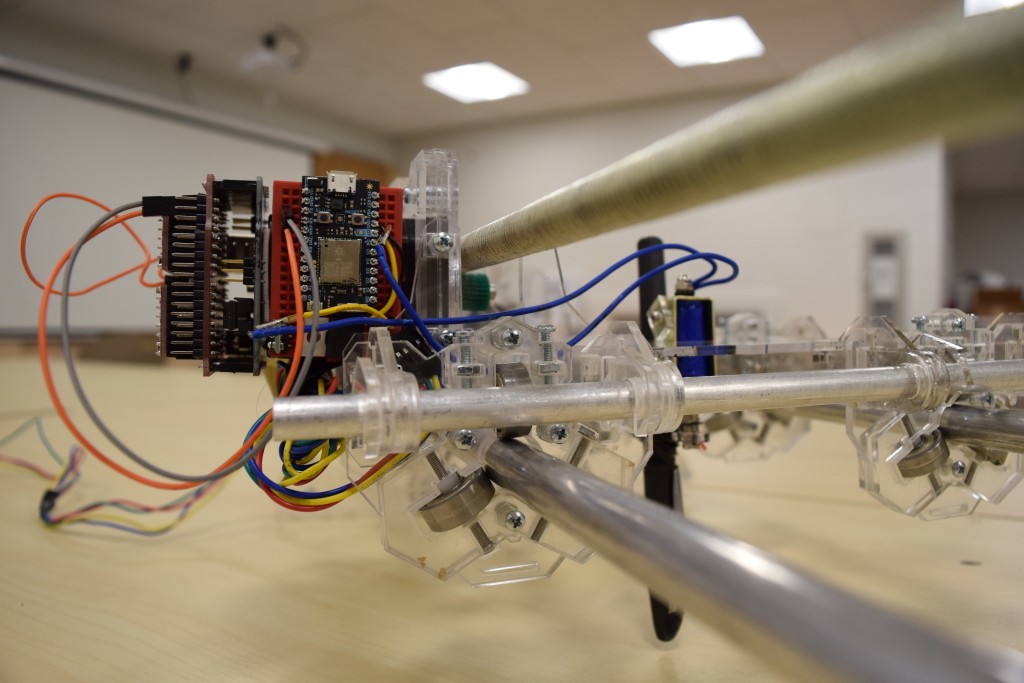
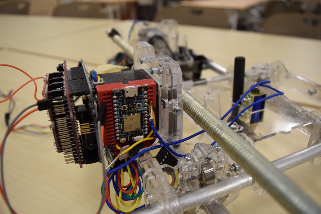
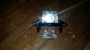
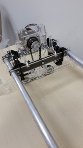
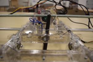
This prototype builds on a custom CNC machine that was designed last semester. The structure was made constructed laser-cut acrylic parts and threaded rods. The build uses three 12V Nema 17 motors for movement on the X and Y axis. For the Z axis, we used one 12V solenoid to lift and release a whiteboard marker. One modification we made to the CNC-style design is adding tank style treads as a replacement for the Y axis allowing the machine to move continuously in that axis.
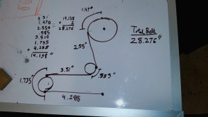
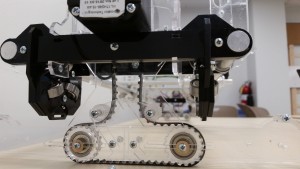
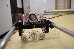
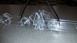
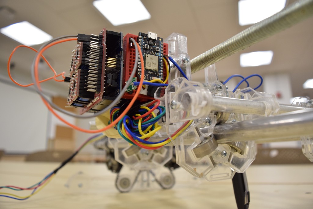
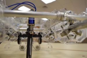
The wheel assembly uses two idler wheels and belt pulleys to feed a belt around the main gear, driven by a stepper motor. The outside idler wheels balance the structure so that the belt is always in contact with the dry-erase table. Embedded in each of the two idler wheels there are bearings held in place with a screw. The screw slot can be adjusted to easily manipulated the tension on the wheel belt.
We came across many hurdles while designing the wheel assembly. At first, because the drive gear was too large, the torque ratio was disturbed and the wheels could not move forward.
Another issue we ran across was that the wheels had a tendency to skew inwards because they were only supported on one side. This caused the belt to catch and sometimes make the machine slide across the table. There was also a lot of friction between the pulleys and the side wall.
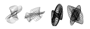
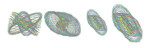
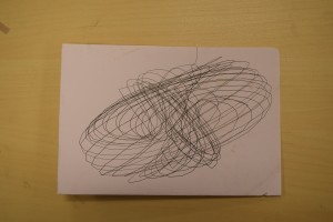
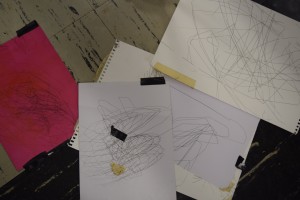
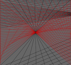
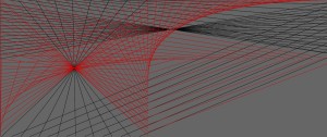
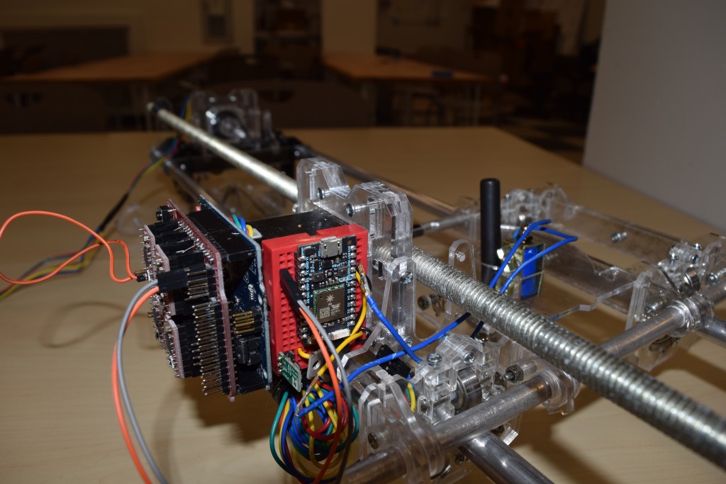
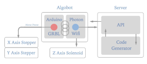
To generate algorithmic patterns, we used Processing to easily visualize the patterns. The pattern shown in the video generates a random sequence of points to draws in between, based on varying functions. Other experimental patterns were tested based on the fundamentals of harmonic motion. This code was then ported to javascript, so it could be generated by the server. When the wireless Photon board starts up it connects to an external server on the network. This server generates the GCode at each request based on the line that the controller is currently on.
EX
GET http://192.168.1.100:7000/<current_line_number>
GET http://192.168.1.100:7000/1
Returning
G0 X100 Y100
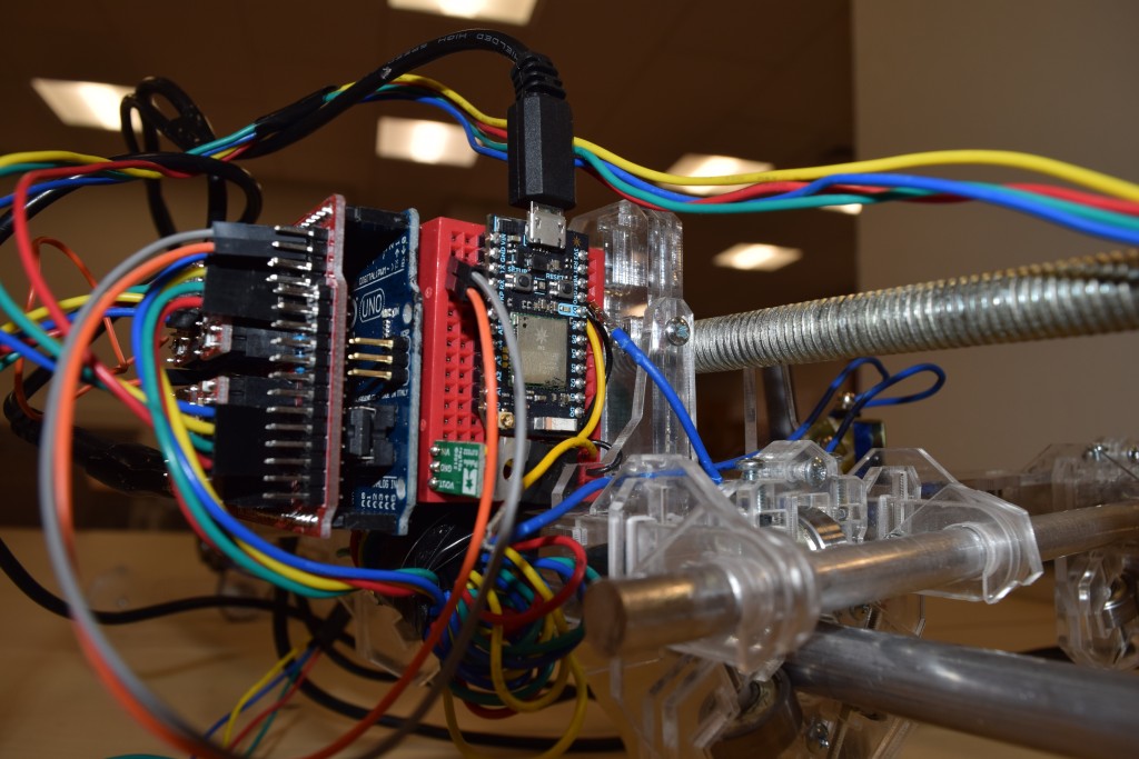
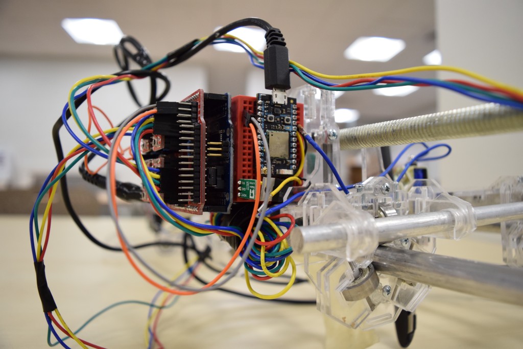
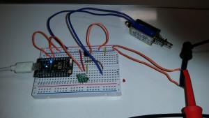
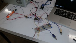
The photon then parses the packet which contains the motor control commands, and sends them over the TX/RX pins to an Arduino controlling the motors. Every time the Photon reads the “ok” from the motor controller, it passes the next command over serial then requests the next command. The reason we used both controllers was so we could delegate motor control to one board and wireless communication to the other. This structure allows the next line of motor controls to be primed before it’s required, which essentially makes the movements smooth.
Discussion
Leave a Reply