For the project 1. We adapted Computer Vision and Image Processing techniques to detect the marks on board.
To make use of an external webcam, I installed imagesnap on OS X. You can install it through Homebrew or other package manager:
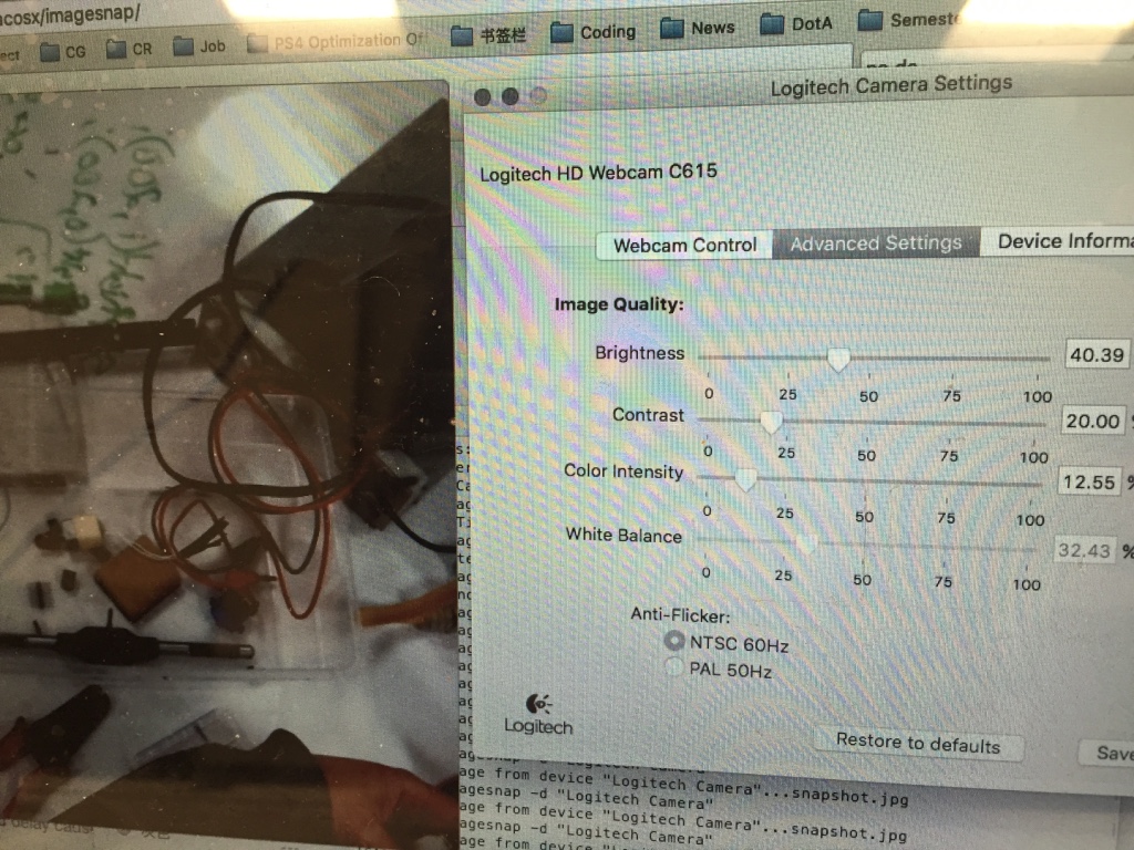
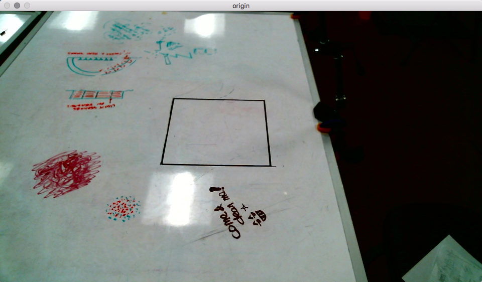
Applying some adjustments to the web camera to increase the contrast of the marks and whiteboard for detection convenience:
The first step is setting up OpenCV library using CMake on OS X. I followed the steps in this post:
http://blogs.wcode.org/2014/10/howto-install-build-and-use-opencv-macosx-10-10/
Based on the image snaps from the external web camera. I did camera calibration first. I followed the camera calibration project built in OpenCV library:
This is a part of the camera data I got:
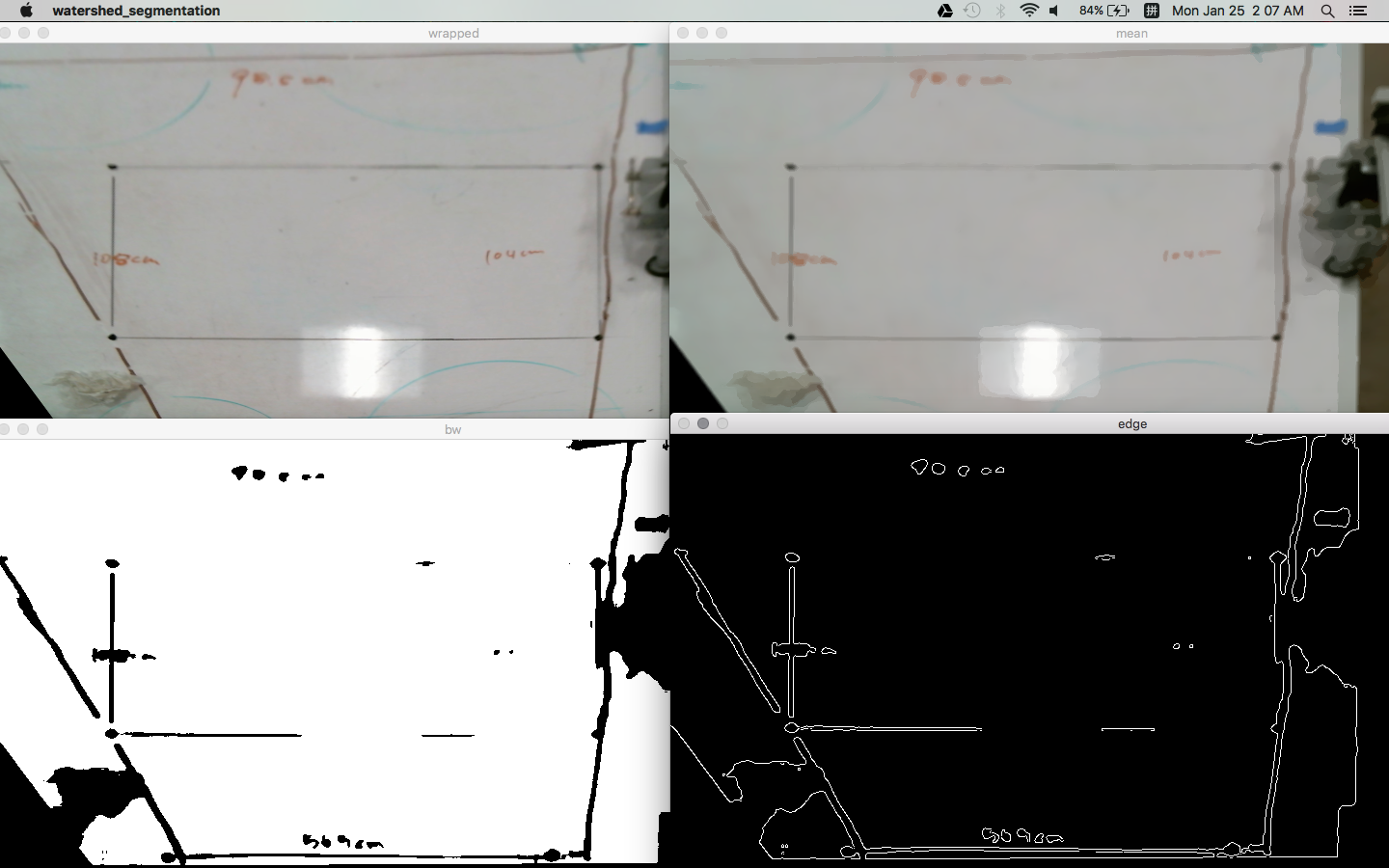
Then each time when doing mark detection, preprocess the captured image first.
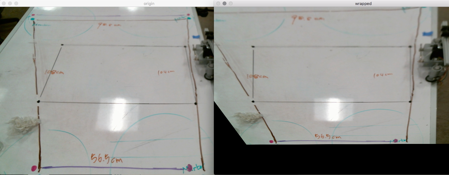
After camera calibration. We need to do a projective transform for the image though. OpenCV has a function: getPerspectiveTransform() (cv::getPerspectiveTransform(const Point2f src[], const Point2f dst[])) Which can be used for the purpose. I just used 4 points’ corresponding relationship during the transformation for the implementation:
Considering the purpose of the project: we want to clean the marks on the whiteboard. The foreground(marks) and background(whiteboard) are distinguishable in common case due to the high contrast.
When I tried to figure out what method to apply for marks detection. I thought about watershed segmentation at first. It has a good performance while distinguish connected region, thus can provide a relatively more accurate result. (An example of the implementation of watershed algorithm can be found here:
http://www.pyimagesearch.com/2015/11/02/watershed-opencv/)
An example result of the watershed segmentation:
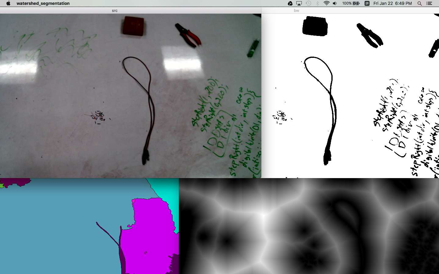
However, actually the goal for the project is pointing to the opposite way: instead of differentiating connected marks as separate objects, we would like a more “rough” result: that is we want to cluster the marks near to each other as the same object.
So I went for threshold and contour the image, then applied bounding box for each contour. The built in sample in OpenCV tutorial can be found here:
http://docs.opencv.org/master/da/d0c/tutorial_bounding_rects_circles.html#gsc.tab=0
Till now, the result is yet not ideal enough:
The writing which should be regarded as a single object were departed as much smaller components.
So we need to cluster the nearby contours.
I thought about using k-means clustering. However, we don’t know how many clusters(objects) in the image(that’s exactly what we want to know!). That means we don’t know “k” from k-means. No way to start training.
Then I thought it’s just ok to do distance detection among the contours. And merge the contours within a certain distance.
There are also some references of the realization:
http://stackoverflow.com/questions/23842940/clustering-image-segments-in-opencv
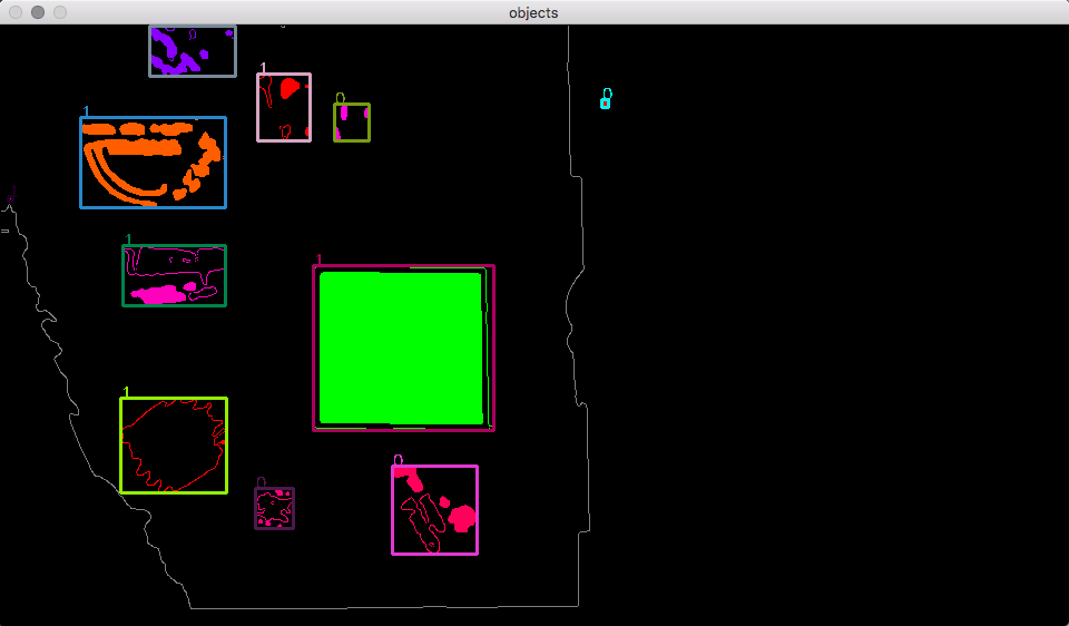
Then we got the final result:
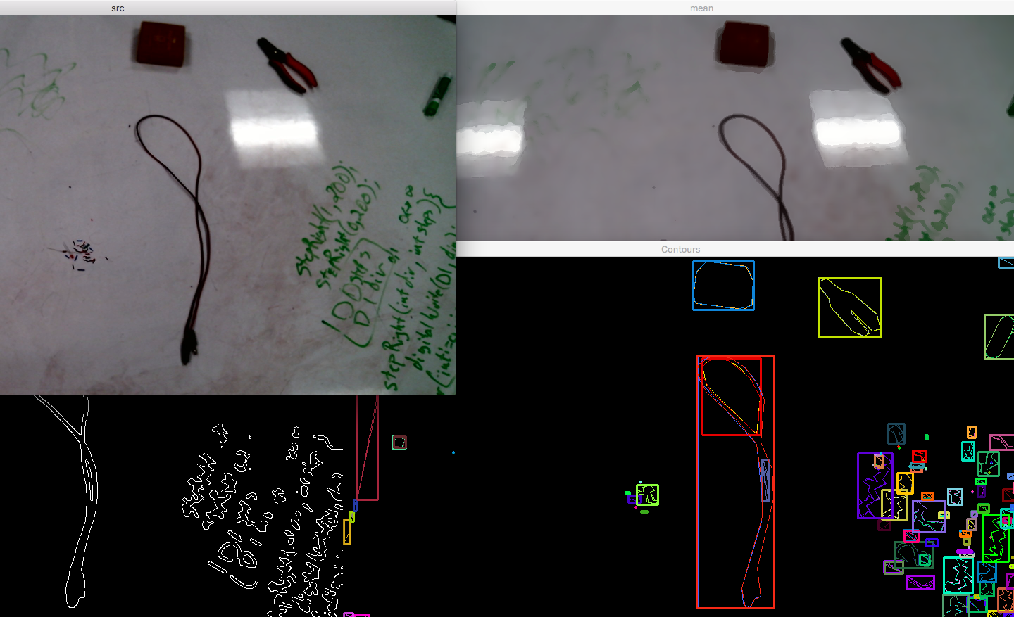
During the contour detection process. In order to get more robust result. Low-pass filtering and thresholding should be applied. Also, after the perspective wrapping process. More noise will be introduced into the system(mostly along the outline of the image). It’s shown that applying edge detection before contouring is also a good defense to noise:
After the marks detection. The datas we got are: the corner position of the marks’ bounding box, as well as the width and height of the region:
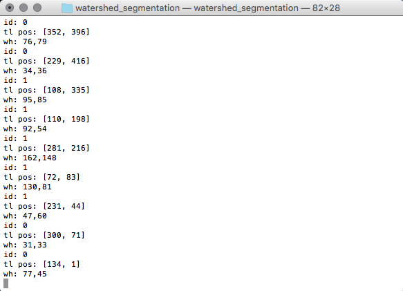
We then transfer these datas to photon for the following mechanical function realization.
As for the mechanical function part. We drive 2 step motor separately according to the position and size of the marks.
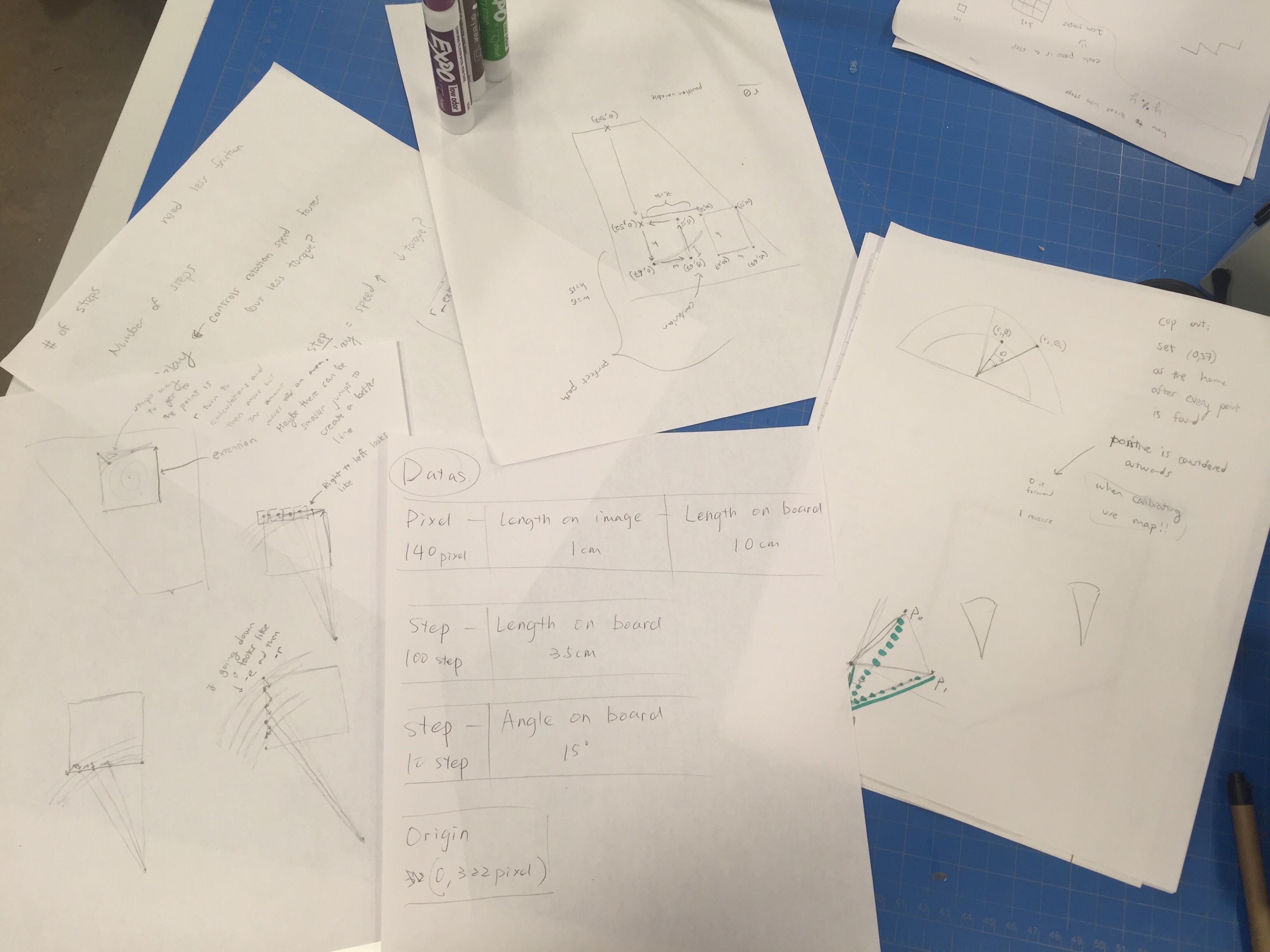
When applying data transferring. We set an origin in the image. And adding offsets to the value of data according to the origin. Then we convert the xy-coordinate data to polar-coordinate. The radius and the angle values each drives a motor.
The scalar relationship between image, whiteboard and motor:
Final result:
The links of the code:
Leave a Reply