Mobile Robot: “Magic 8 Bot”
|
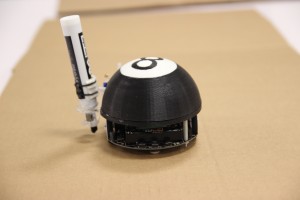
Group Members: Jaime Chu, Susan Zuo For this assignment, we were given a Pololu 3pi Robot, and since it was a fun environment, we wanted to create a fun project to match. We had the concept to make our 3pi draw using its movements and decided it would be interesting to recreate the Magic 8 Ball with improvements.
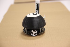
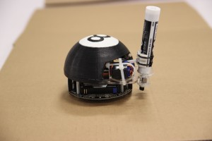
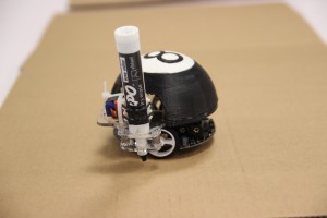
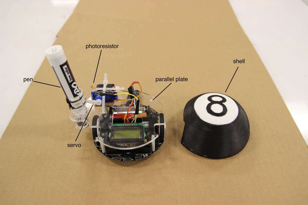
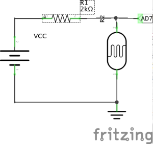
Like many other projects we split up this project into three different sections, the mechanical work, hardware and the software. The mechanical work included the parallel plate modeling, the shell modeling, and the pen lifting mechanism. The hardware included the wiring of the servo and photoresistor. Finally, the software included the integration of all the physical parts as well as the actual motor drive. Mechanical: Each part was created from different machines. The parallel plate was laser cut, while the dome was 3D printed and then hand painted. The lifting mechanism was created using a servo and a lift attached to the pen. The lift was created using a rigid edge found from the lab and attached using two O-rings. This was designed so that when the servo dropped the pen, the downward force comes from only gravity itself. Hardware: The servo was connected with a digital output pin IO_D0, Vbatt, and Gnd (see image right), while the photoresistor was connected with an analog input pin IO_AD7 (see left image). The photoresistor was wired with a voltage divider of a 2K ohm resistor and the photoresistor connected to Vcc and Gnd. Alternative sensors could also be used in order to get different responses. Software: For each of the pieces, integration for the servo and photoresistor was done by using the example codes provided by Pololu. However, the actual motor driving code was done with manual calibration. This task was the most difficult because it required that the battery voltage maintained constant voltage or the drive would act differently. See the ad: YouTube / Jaime C – via Iframely See the use of the Magic 8 Bot: YouTube / Susan Zuo – via Iframely |

