Homework 2: Blinky party
Due at the start of class on Tuesday, September 3rd
There are two homeworks to do for Tuesday:
- Read through the entire “Policies, expectations, housekeeping” page for this course. (It’s linked under the “reference” header on the left column of this page.) If you read through it on your own time, we won’t need to spend class time covering it!
- Complete the LED-blinking assignment described below.
Get excited for some thrilling LED blinking!
Below is a little graph of three LEDs over time. Whenever an LED’s line appears, it’s on, and whenever it disappears, it’s off.
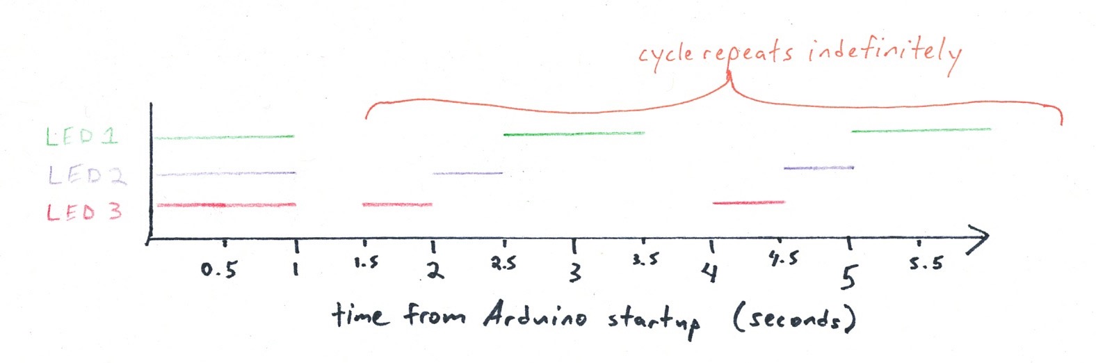
Just in case you’d prefer it in words: all three LEDs will be on for one second when the Arduino first starts up. Then they will all turn off for a half second. Then LED3 turns on for a half second and back off. Then LED2 turns on for a half second and back off. Then LED1 turns on for a second and back off, and then all three are off for a half second. The cycle then repeats indefinitely.
Your assignment:
-
Build a system where three LEDs blink in the pattern described above. The LEDs’ colors don’t matter. Use your breadboard.
-
Make it so that every time LED1 changes status (i.e. every time it turns on or off), the Arduino sends a serial message back to the computer saying so. The message stream should look like:
        LED1 is on
        LED1 is off
        LED1 is on
        LED1 is off
        ...
Deliverables
-
Demonstrate your working LED blinky party at the start of class on Tuesday.
-
Draw a schematic for the circuit(s) you build. Make your drawing on paper, and don’t worry about lines being perfectly straight, etc. You can use the schematic we drew in class as a sort of style guide. Use a piece of unlined 8-1/2”×11” paper, and put your name on it: you’ll be handing it in.
-
Submit your code to the Canvas assignment. The top of your submitted code should have the standard comment block that’s specified in the course policies page, reproduced below for your convenience:
/*
 * Homework 3
 * Andrew Carnegie (acarnegi)
 * 1 hour 25 minutes
 *
 * Collaboration: Ada Lovelace helped me understand
 * variables and we worked on the code together.
 * The function "Wheel" is copied from this Adafruit
 * tutorial: https://learn.adafruit.com/multi-tasking-the-arduino-part-3/utility-functions
 *
 * Challenge: I tried to write a switch…case but
 * it did not go as planned. It took me an extra hour!
 * I was held up with bracket trouble the whole time,
 * it seems.
 *
 * Next time: I'll start by writing comments or pseudo-code
 * before trying to write the actual code. I think this
 * will reduce my getting tangled around the code
 * structure.
 *
 * Summary: The code below blinks three LEDs according
 * to a pre-defined pattern.
 *
 * Inputs: none
 *
 * Outputs:
 *  Arduino pin | output
 *  4             blue LED
 *  6             green LED
 *  9             red LED
 */
The filename you submit should be andrewID-hw-2.ino. (ino is the extension for Arduino files; you don’t need to add it manually to the end of an Arduino file name.)
⚠ For those of you new to electronics ⚠
There is one big wiring mistake that people sometimes make when they’re first learning this material.
Do not connect the power (which means 5V, or any other Arduino pin that is an OUTPUT) directly to ground.
In other words, no wire should directly go from 5V to GND. If you make this mistake, you may destroy the Arduino (which is a $10 loss, and not the end of the world). It is also possible to harm the computer connected to the Arduino!
If at any point the Arduino or any wires attached to it become warm/hot, immediately unplug the Arduino from your computer. Check your wiring—you probably have connected power to ground somewhere.
How do I use a breadboard?
The good people at SparkFun (an education-market-focused electronics supplier) have a nice tutorial https://learn.sparkfun.com/tutorials/how-to-use-a-breadboard/ which covers what we talked about in class plus some extra history which is interesting.
Wiring a single LED up
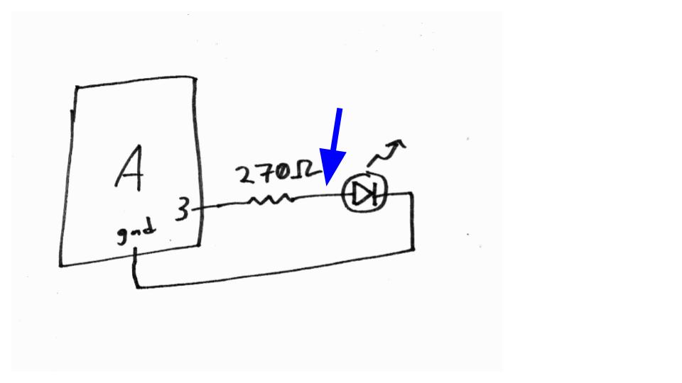
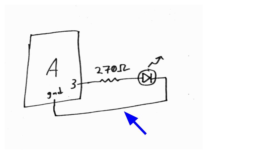
In class we drew this schematic to represent how to power a single LED from the Arduino:
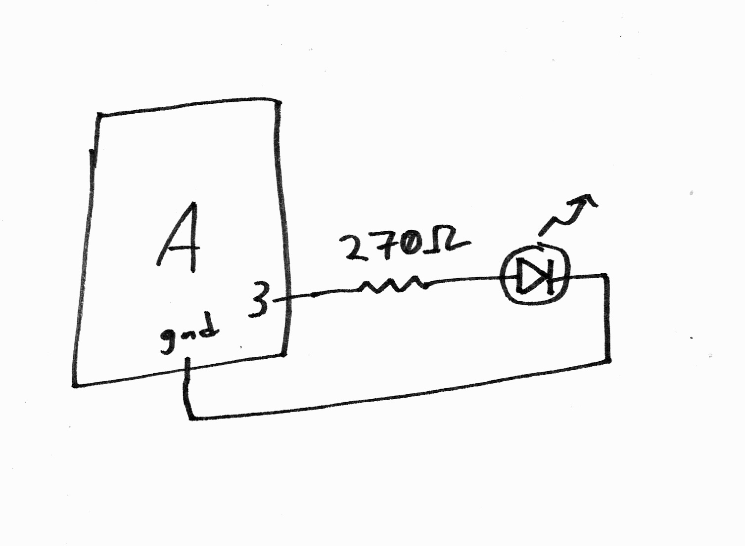
If the circuit you make matches the drawing, to get the LED to light up, we simply need to tell the Arduino to “turn on” power on pin 3. This can be accomplished thusly: digitalWrite(3, HIGH);. (You can probably guess how to turn off that LED in code.)
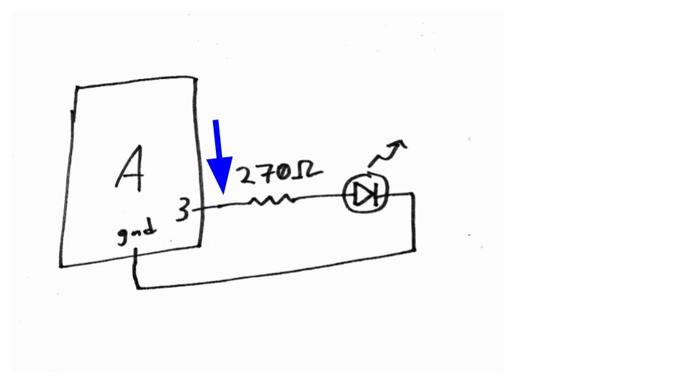
Perhaps you’re not sure how to go about actually wiring the circuit up, though. Below, we’re going to keep referring back to the schematic, and relating each part of it to the wiring in the real world. By going systematically through the schematic, we’ll be assured of translating it into a viable and correct circuit in the world.
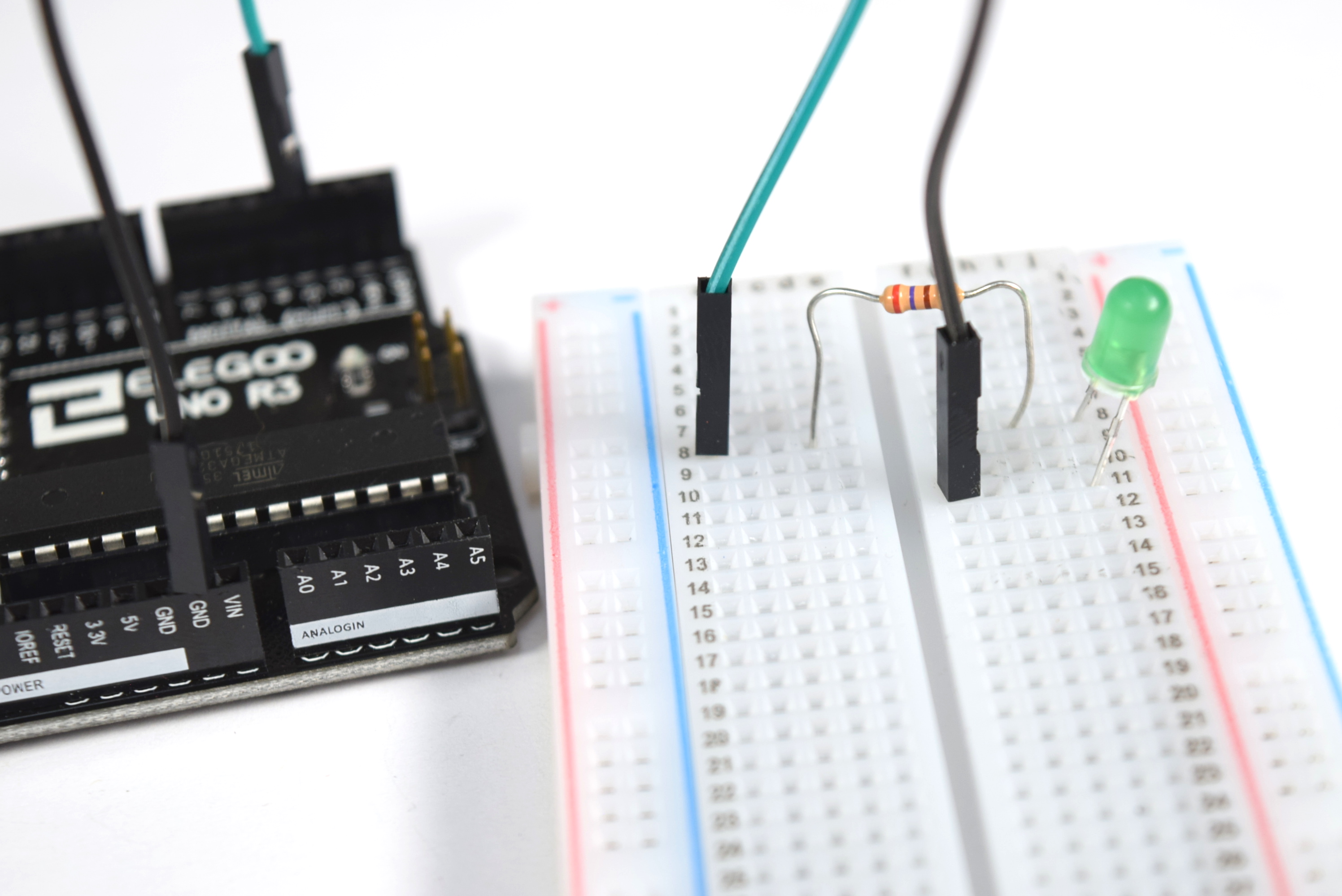
1. Connect Arduino pin 3 to one side of the 270Ω resistor
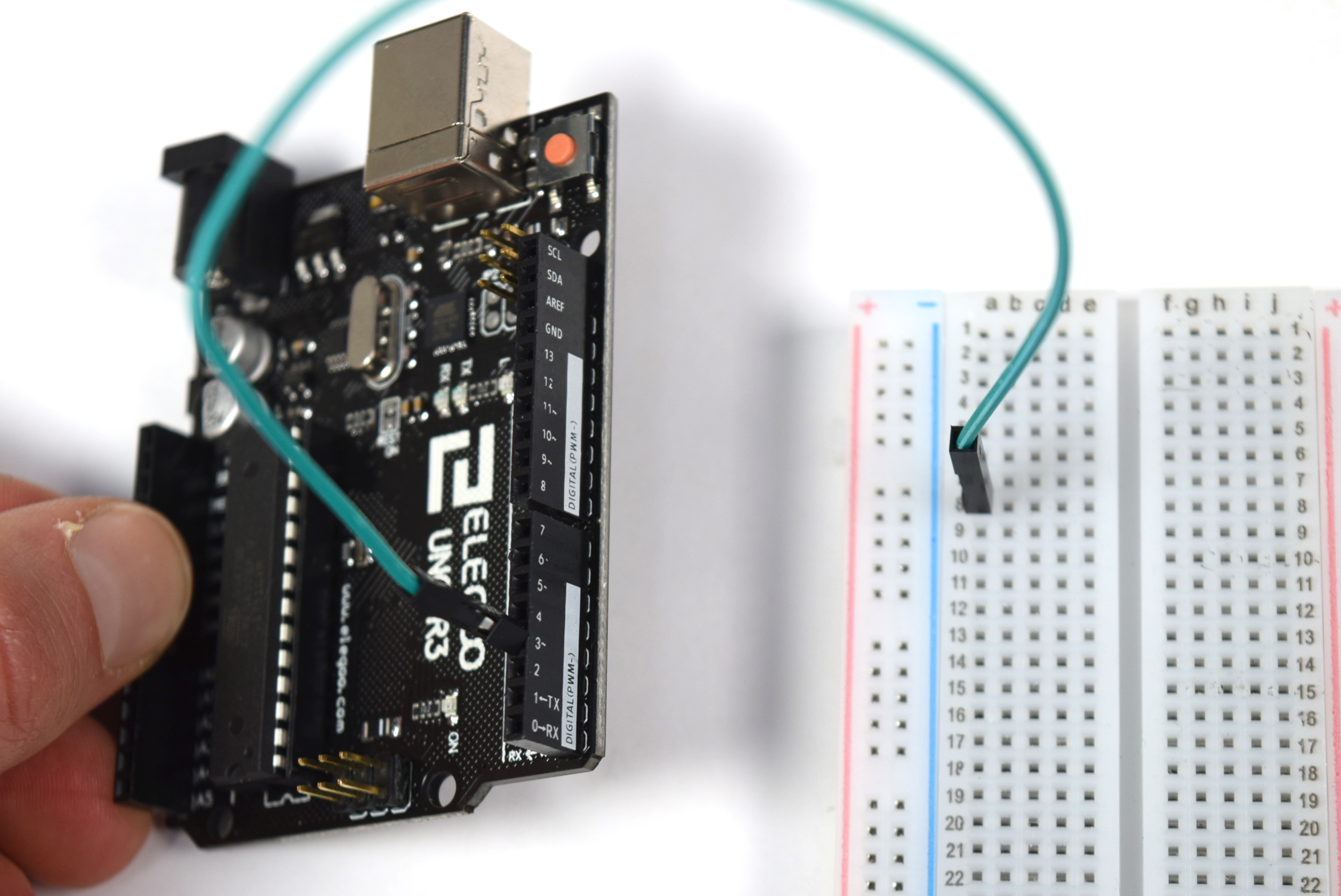
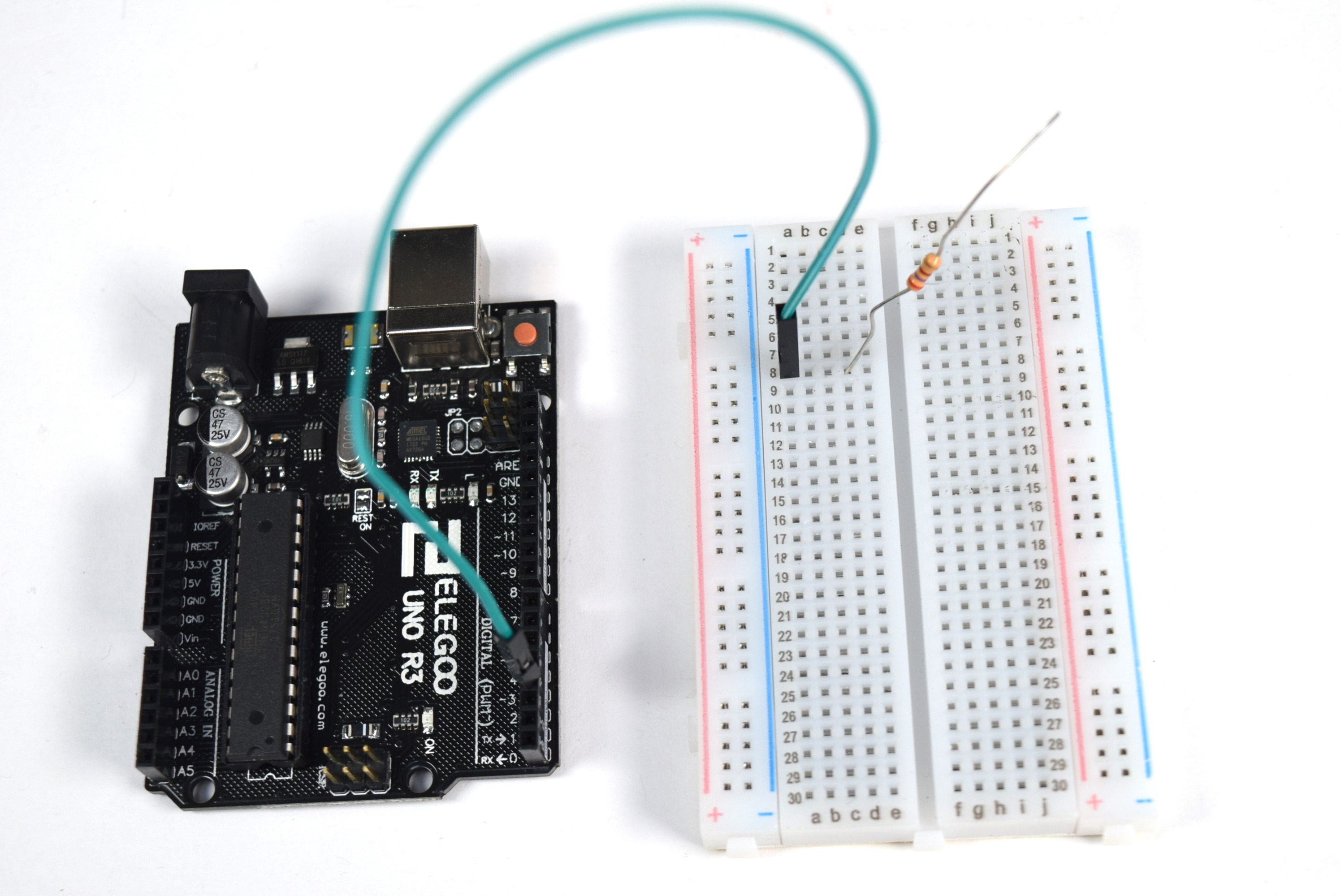
Q: What color wire should I use? The Arduino does not know or care what color wires you’re using. However, you will help yourself greatly by choosing good colors; in this example, matching the wire color to the LED color will help keep things clear.
Q: Why use row 8 on the breadboard? No reason at all; this is totally arbitrary. The Arduino has no idea what row it’s plugged in to and doesn’t care about the number. It knows its own pin numbers (i.e. pin 3 in this case), but doesn’t have any way of knowing what external wiring you’ve done.
Q: Which side of the resistor should I attach to the Arduino connection, and which side to the LED connection? In the case of a resistor, which does not have “polarity,” it doesn’t matter. Either direction will work the same.
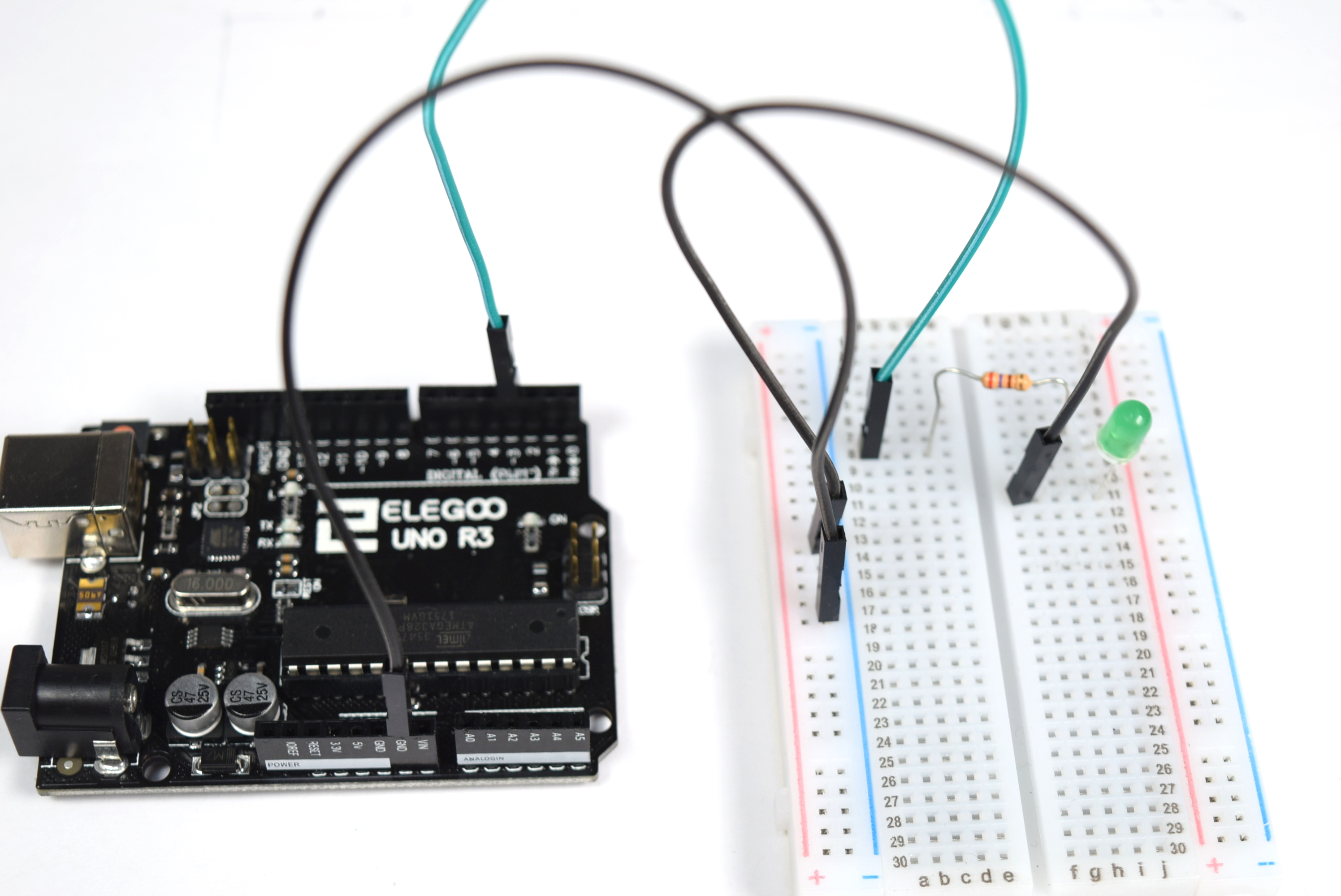
2. Connect the other side of the resistor to the positive leg of the LED
Where will we make this connection, between the “other” leg of the resistor and the LED? Anywhere we want. We can hop over the center divider to the other side of the breadboard, or keep using only the left side of the breadboard; it’s a question of style rather than substantive difference.
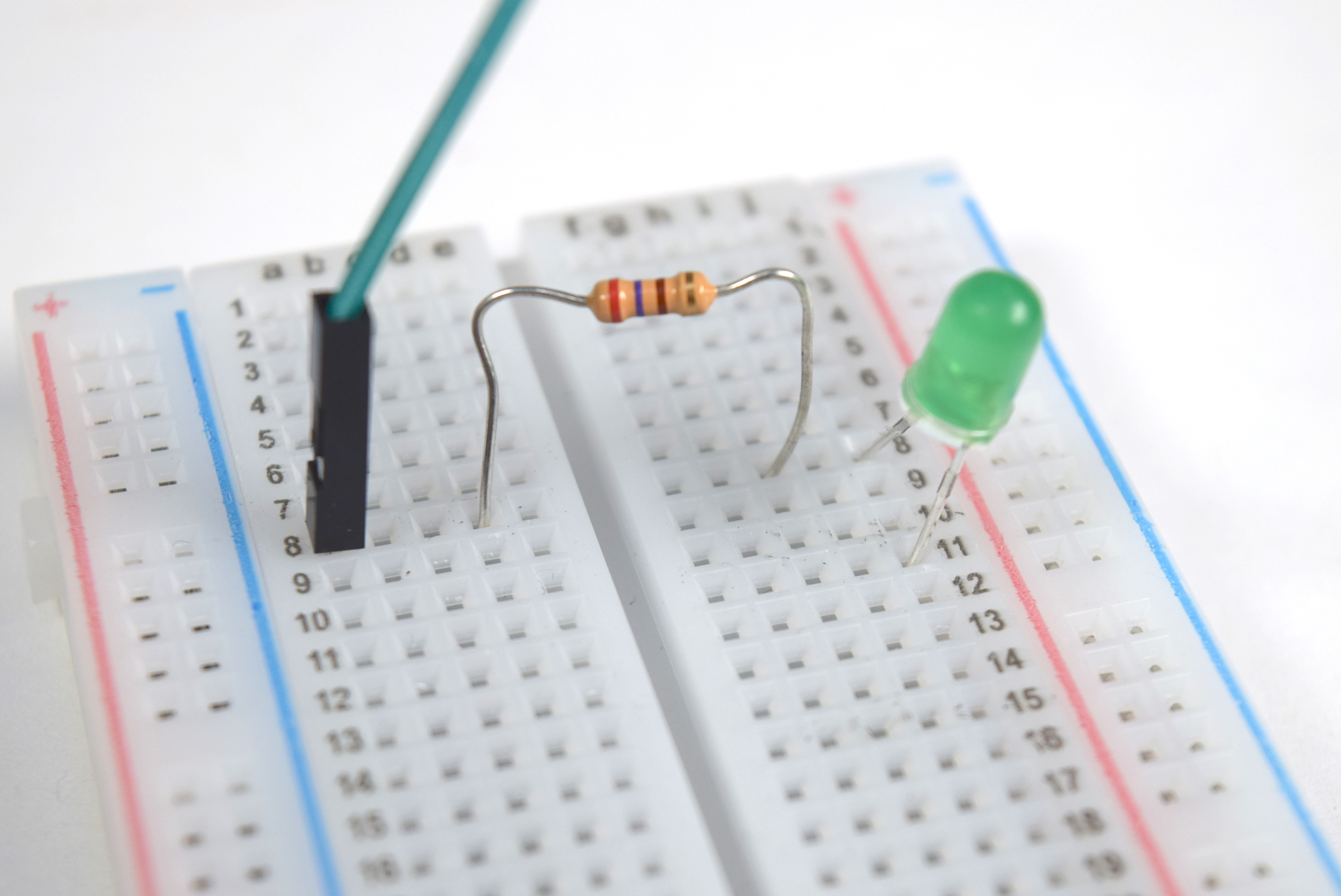
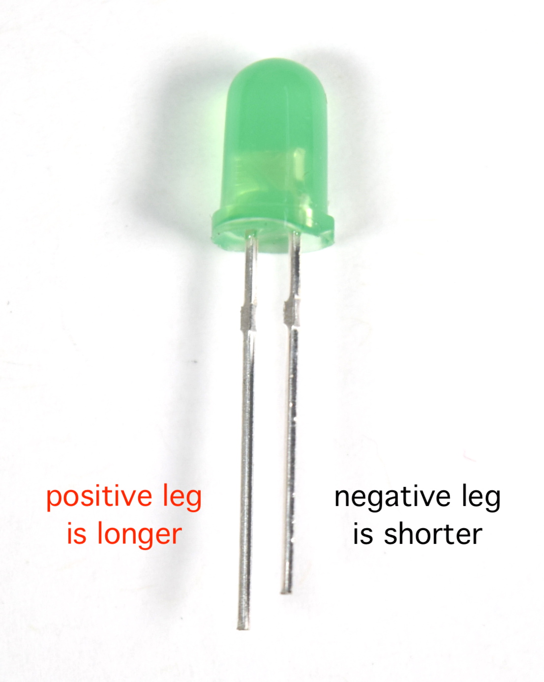
Q: Which LED leg is which? The LED, unlike a resistor, does have polarity. In order for power to flow through it (and for it to light up), the power should go into the longer leg, and then out of the shorter leg. Wiring the LED backwards will not harm it; it simply won’t light up because power won’t flow through it.
3. Connect the negative leg of the LED back to the ground
Finally we make the last connection, from the negative leg of the LED to the Arduino’s ground. We use a black wire for this because conventionally black wires are used for ground or negative.
4. Adding more LEDs
Once you’ve got one LED wired properly, it won’t be difficult to add more of them.
Each output LED should be driven by its own Arduino pin, have its own resistor, and have its own connection to ground.
So far in this tutorial, we’ve wired a green LED to pin 3, so if you’re going to add a red LED, you can drive that LED off of any other Arduino pin you like (avoiding pins 0 and 1 for reasons we’ll discuss in class).
Q: Help! I’m running out of grounds to plug into. Once you’ve wired three LEDs, you’ll need three grounds, one for each. Fortunately, we can use the breadboard’s “power rail”—that’s the long connections that run up and down the left and right sides—to solve this problem, connect the Arduino ground to the power rail marked with the minus sign, and then you can plug in any wire that needs to go to ground anywhere you’d like along that whole column:
Q: My LEDs are all working, but they’re very dim. My wiring looks fine. What’s wrong? Make sure you used the correct pinMode() command for all of the outputs you’re using.
I don’t know how to do the Serial part of the assignment
We’re going to learn a new trick, something we didn’t have time to get to in class, to do part 2 of the homework.
It is possible to tell the Arduino to communicate something back to the computer as it is running. We do this using a feature called “serial communication,” and once you get the hang of it, you’ll find it very useful.
Here’s how you implement serial communication:
1) Tell the Arduino to turn on its serial port. How? With the command Serial.begin(9600);. Since you only need to do this once, the usual practice is to put it somewhere inside of the setup, like so:
void setup(){
    Serial.begin(9600);
}
Of course your setup can contain as many instructions as you’d like; for instance, it could look like:
void setup(){
    pinMode(13, OUTPUT);
    pinMode(10, OUTPUT);
    digitalWrite(13, HIGH);
    Serial.begin(9600);
}
2) Then, as part of the instructions you’re writing, tell the Arduino precisely what text you want it to send to the computer. (If you know about console feedback then this will be familiar.) The command to tell the Arduino to transmit the text hello is: Serial.println("hello");. Therefore, the command to tell the Arduino to transmit the text LED1 is on is simply Serial.println("LED1 is on");. You will need to figure out where to put the serial commands in your code so that the Arduino transmits the right messages at the right time.
3) To see the serial messages that the Arduino is transmitting to the computer, click on the little magnifying glass in the upper right corner of the Arduino code window:
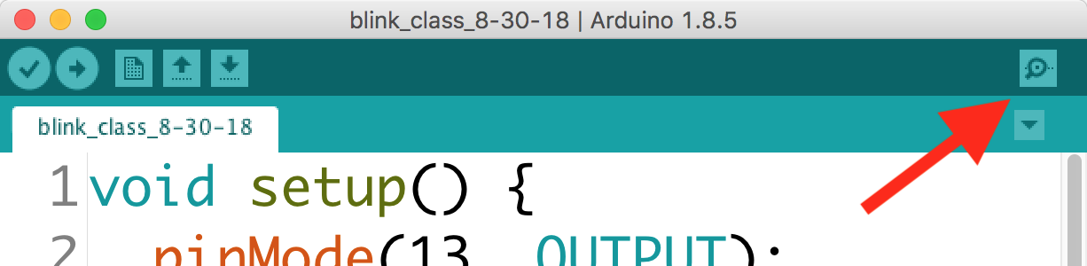
A window called the “serial monitor” will open up and display your messages. If it’s working properly, it’ll look like this:
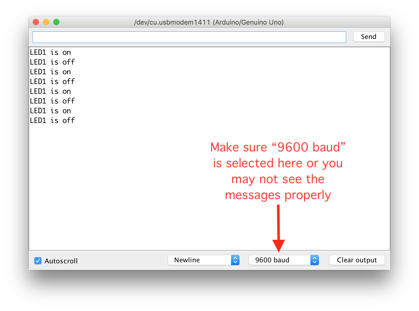
Remember, if you want to restart your Arduino, you can always push the little red “reset” button that’s above the USB connector on the board. Also, you’ll discover that every time you open the serial monitor window it will restart automatically. (Restarting takes less than a second so this is no big deal.)
Collaboration and help
You are welcome to collaborate with your classmates, friends, etc., on this homework assignment. Look up help in any source that you find useful, including the web, reference books, whatever you’d like to use.
However:
-
You must type out the code you use. That means that while you can copy parts of it from another source, you have to type every single letter yourself! We’re building muscle memory. (If you work with a partner, you can both have identical code, but you must both type it out yourself.)
-
You must build your own circuit. You can make the same circuit your friend does, but you have to actually use your own hands to make yours.
-
You must draw your own schematic. It’s fine if it looks the same as your partner’s (I expect nearly every schematic in the class to look quite similar) but you have to draw it yourself.
Questions? Concerns? Email the instructor or TA and ask! We’re here to help.
