
Photo of the entire project. Magnet switch and magnet on the left, flex sensor and servo in the bottom center, and vibration motor on the right.
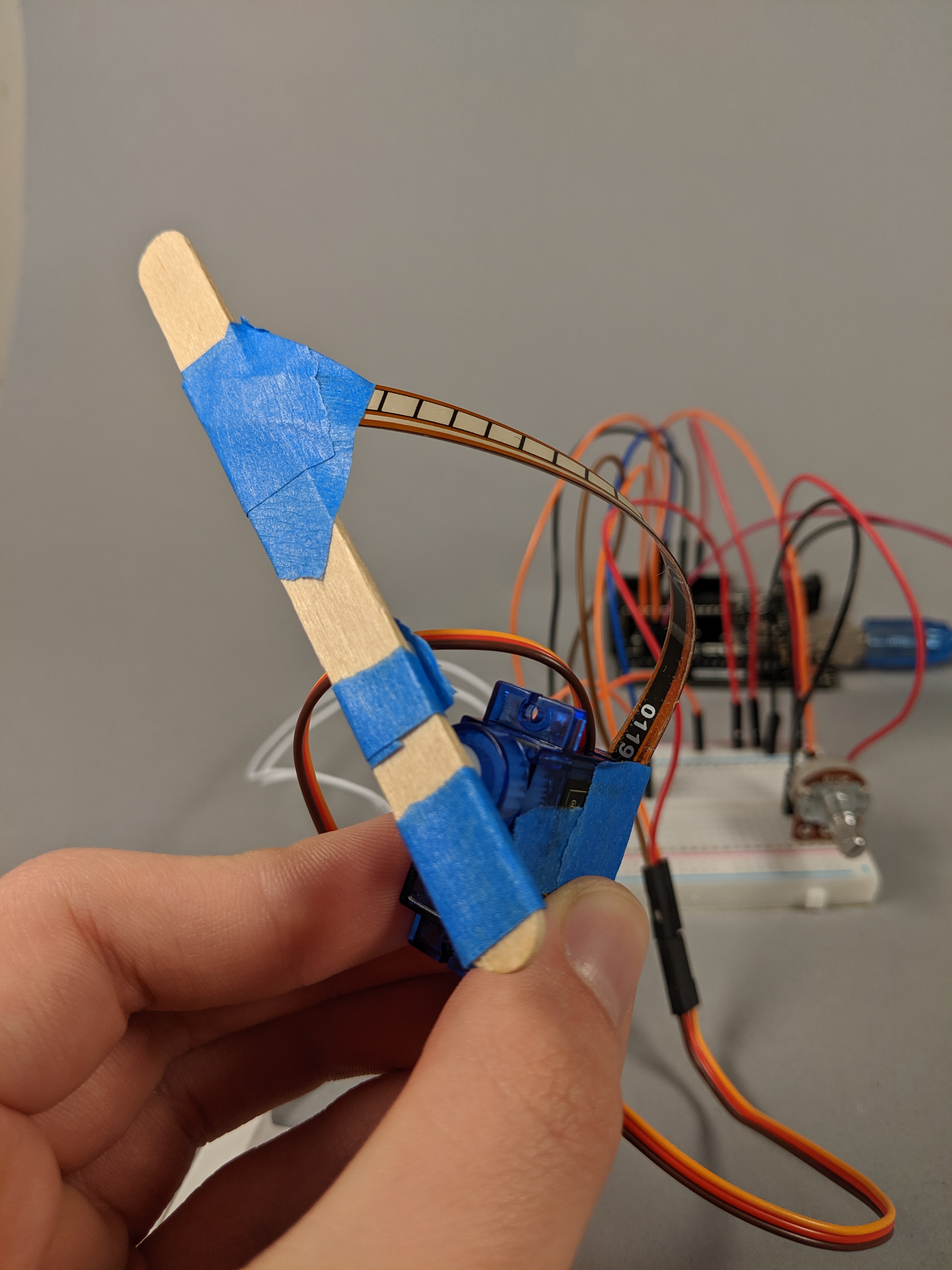
The servo and flex sensor mechanism. We extended the arm of the servo to increase the range of motion we bend the flex sensor through.
The transducer in action. A magnet activates the reed switch, which rotates the servo, which flexes the flex sensor, which activates the vibration motor.
Description:
A magnetic switch waits for the presence of a magnet. When the switch is activated, it triggers a motor to spin a lever. The spinning lever twists the flex sensor, which causes it to activate the vibration motor.
Progress:
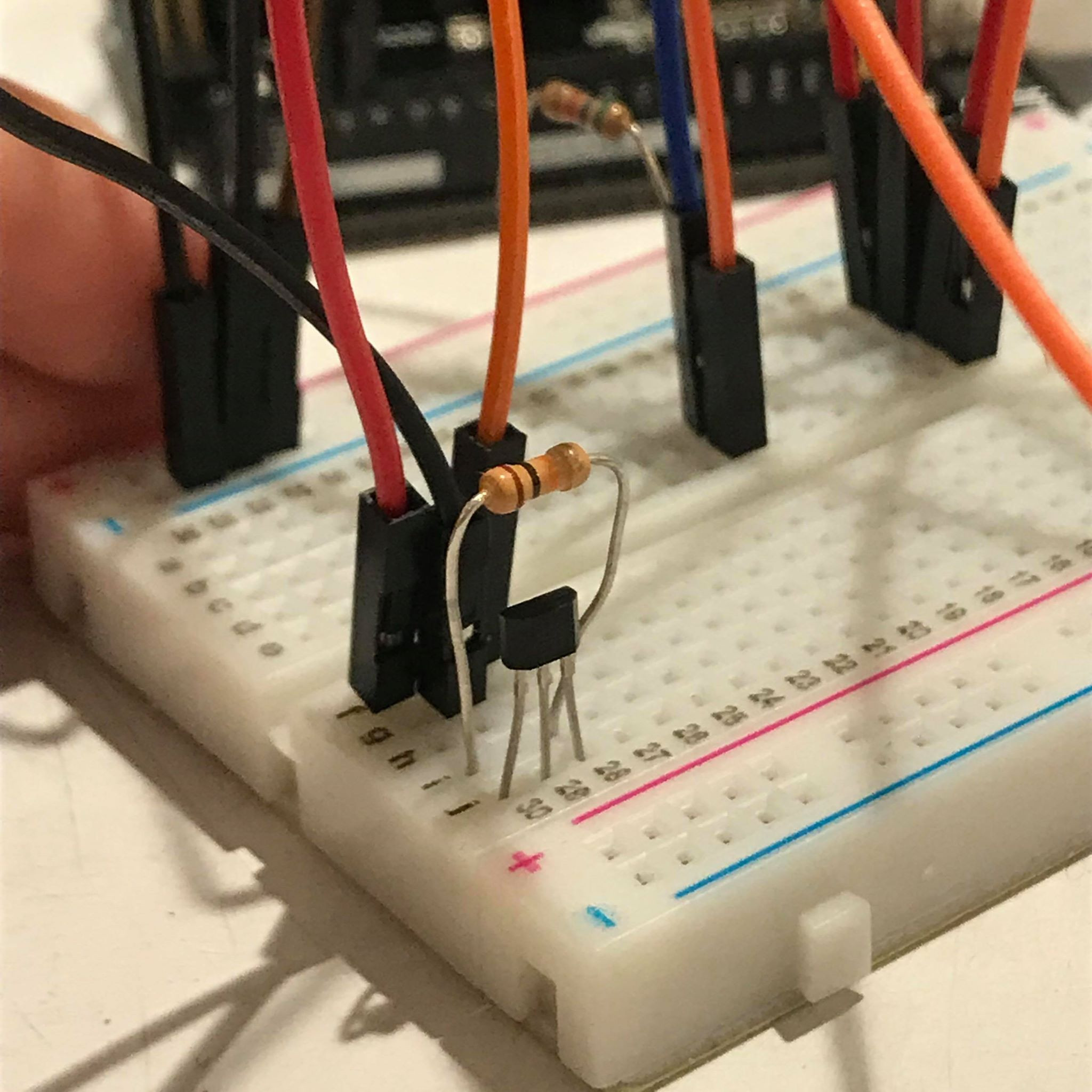
Testing the US1881 Hall Effect Sensor. We found this sensor to be about as sensitive as the physical reed-switch.
Our first tests of the servo and flex sensor mechanism. We discovered that the values of the flex sensor didn’t cover a very wide range, and were susceptible to noise.
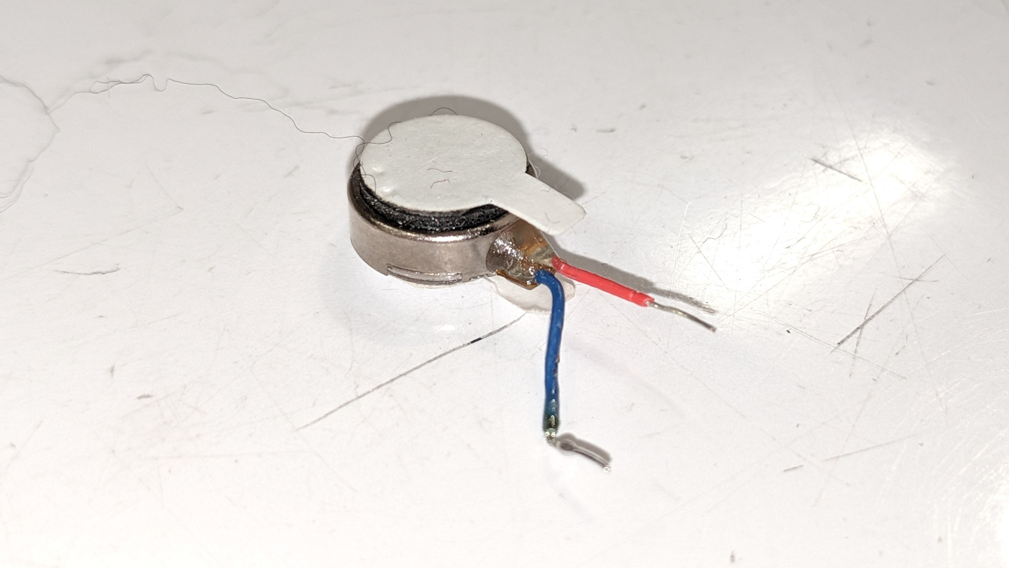
The original vibration motor we chose for our output. The leads proved to be too small to solder easily, so we selected a different motor with larger connections.
Discussion:
We investigated two different methods of detecting a magnetic field for our input: a physical reed switch, and a semiconductor Hall-Effect sensor (US1881). We found both of them to have similar sensitivity, though the Hall-Effect sensor had an interesting latching behavior. Once activated by a magnetic field, it would continue to send an “on” signal until it detected another magnetic field in the other direction. We decided to use the reed switch instead, as it would be simpler for the group providing our input to change the presence of a magnetic field rather than the direction.
Our servo and flex sensor mechanism proved to be an interesting construction challenge. Specifically, we needed a system which could flex the sensor in as wide a range of motion as possible. Because of this, we extended the arm of the servo to rotate over a wider range. We also faced challenges using the flex sensor, from its low range of output values to its fragile design. Specifically, we faced the problem of loose connections on the sensor, as the motion of the system would occasionally pull the sensor pins from the wire plugs they were inserted in. We mostly resolved the connection issue by reconstructing the mechanism with tightly wrapped tape and connections, however the issue of sensitivity remained. To help make our transducer easier to use, we included a calibration dial, to manually determine the set-point at which we consider the sensor flexed. This helped us to avoid making last-minute software changes to adjust the sensor in the case of analog drift.
Our output, a vibration motor proved to be the simplest element of our transducer. We did have some difficulty soldering connections to the part due to its size, however by choosing a different motor, we were able to find one which could be connected to the standard breadboard jumpers. This proved mostly effective until later into in-class testing, when we discovered that the vibration of the motor had managed to loosen its own connections, which we manually reconnected.
Altogether, while our transducer did work as intended, the majority of issues we faced we related to physical problems, rather than electronics or software. Evidently, this shows that the tangible construction of a device can be the limiting factor in terms of its effectiveness. Because of that, we intend to place more attention on the physical layout of our projects in the future to ensure that our electronic and software components can operate without the limitations of poor wiring or construction.
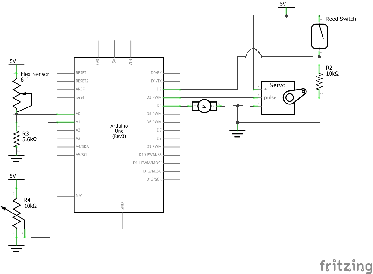
Schematic:
Code:
#include <Servo.h>

/* Project One
 * George Ralph (gdr), Beccy Zheng (rebeccaz)
 * 2 hours 30 minutes
 *
 * Collaboration: Discuss with other groups to coordinate our inputs and outputs.
 *
 * Challenge: One challenge was attaching the flex sensor to the servo motor.
 * The flex sensor pins would get detached and read 0 instead of the actual value.
 * Another challenge was getting the vibration motor to work. We originally
 * tried to solder another type of motor, but it was too small to make a connection.
 * We eventually found a larger motor that was easier to use.
 *
 * Next time: We will plan ahead for how we will assemble the entire project. This
 * includes a better idea of the physical form.
 *
 * Summary: Magnetic Field -> Flex -> Vibration
 *
 * We read a magnetic switch and use that value to drive a servo motor. The motor
 * twists a flex sensor and we use that reading to control a vibration motor. We also
 * have a potentiometer to adjust the threshold of activation we use for the flex sensor.
 *
 *  Inputs:
 *
 *  Arduino Pin | Input
 *     2          Magnet
 *     A0         Flex Sensor
 *     A1         Potentiometer
 *
 *  Outputs:
 *
 *  Arduino pin | Output
 *      3         Servo Motor
 *      4         Vibration Motor
 */

const int MAGNET_PIN    = 2;
const int SERVO_PIN     = 3;
const int VIBRATION_PIN = 4;

const int FLEX_PIN      = A0;
const int POT_PIN       = A1;

Servo servo;

void setup() {
  //Initialize servo connection
  servo.attach(SERVO_PIN);

  //Initialize other IO
  pinMode(MAGNET_PIN,     INPUT);
  pinMode(VIBRATION_PIN, OUTPUT);
  pinMode(FLEX_PIN,       INPUT);
  pinMode(POT_PIN,        INPUT);

  //Initialize the serial connection
  Serial.begin(9600);
}

void loop() {
  //Check the magnet switch
  bool magnetState = digitalRead(MAGNET_PIN);

  //If the switch is on, move the servo to 90 degrees, otherwise to 0
  servo.write(magnetState ? 90 : 0);
  //Wait .5s to give the servo time to move
  delay(500);

  //Read the flex sensor and the dial (setpoint)
  int flexVal = analogRead(FLEX_PIN);
  int dialVal = analogRead(POT_PIN);

  //Print both values as debug information
  Serial.print(flexVal);
  Serial.print("\t");
  Serial.println(dialVal);

  //If the sensor is above the setpoint, turn on the vibration motor
  digitalWrite(VIBRATION_PIN, flexVal > dialVal);

}
Comments are closed.