A footstool that uses a temperature sensor to alarm users when their feet are getting colder so they are able to get up and move around to help their blood flow!
Ever since I was younger, I have always had cold hands and feet. It is typically due to not moving around and sitting all day. Due to classes being remote, it has gotten worse. At my worst, my feet get so cold that they are numb. So, for this project, I wanted to create an anklet sensor that would alarm me when my temperature starts to drop before getting to the lowest degree. However, due to my incompetence, I was unable to follow through but shift it into a footstool.
The video above is exemplifies what happens when the device is in the trigger state and the button is pushed. When the push-button is pressed while in the trigger state, then the device will wait 5 minutes (in the video it is 5 seconds due to time) for the users to move around to raise their tempt. In the meantime, the vibration will turn off, but to make sure the users understands what state the device is in, the LED continues to stay on. Once the time is up, the device will check the user’s temperature again and if it is not at the resting state, then it continues the triggers until it goes up.
The “Device Overview” video shows a user actually using the device. The first part of the clip is when the feet are at the resting state. The second part of the clip exemplifies what happens when the feet are at the trigger state.
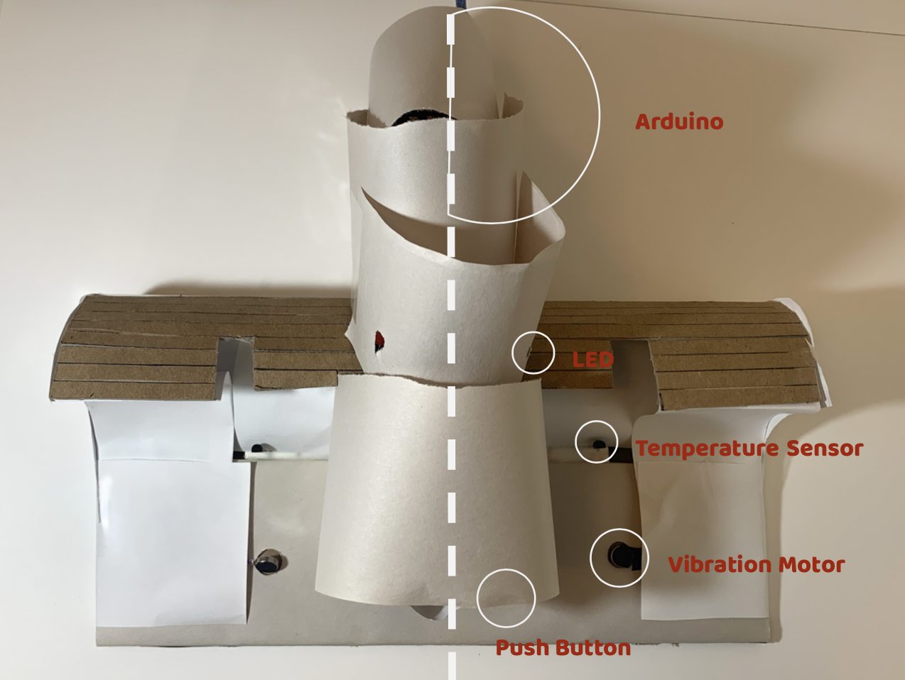
Here is a diagram of the parts of the device!
Process
Before getting to the final concept of making a foot stool, I wanted to create an ankle bracelet that have the same purpose but for only one foot and it is wearable. I started off with mood boarding and doing feet studies on how I could create a device that is wearable, comfortable, and effective.

Here is the mood-board that I created.
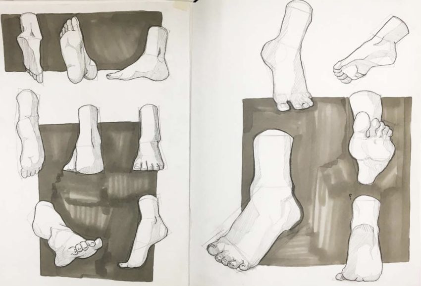
Here is one of the foot studies that I did.
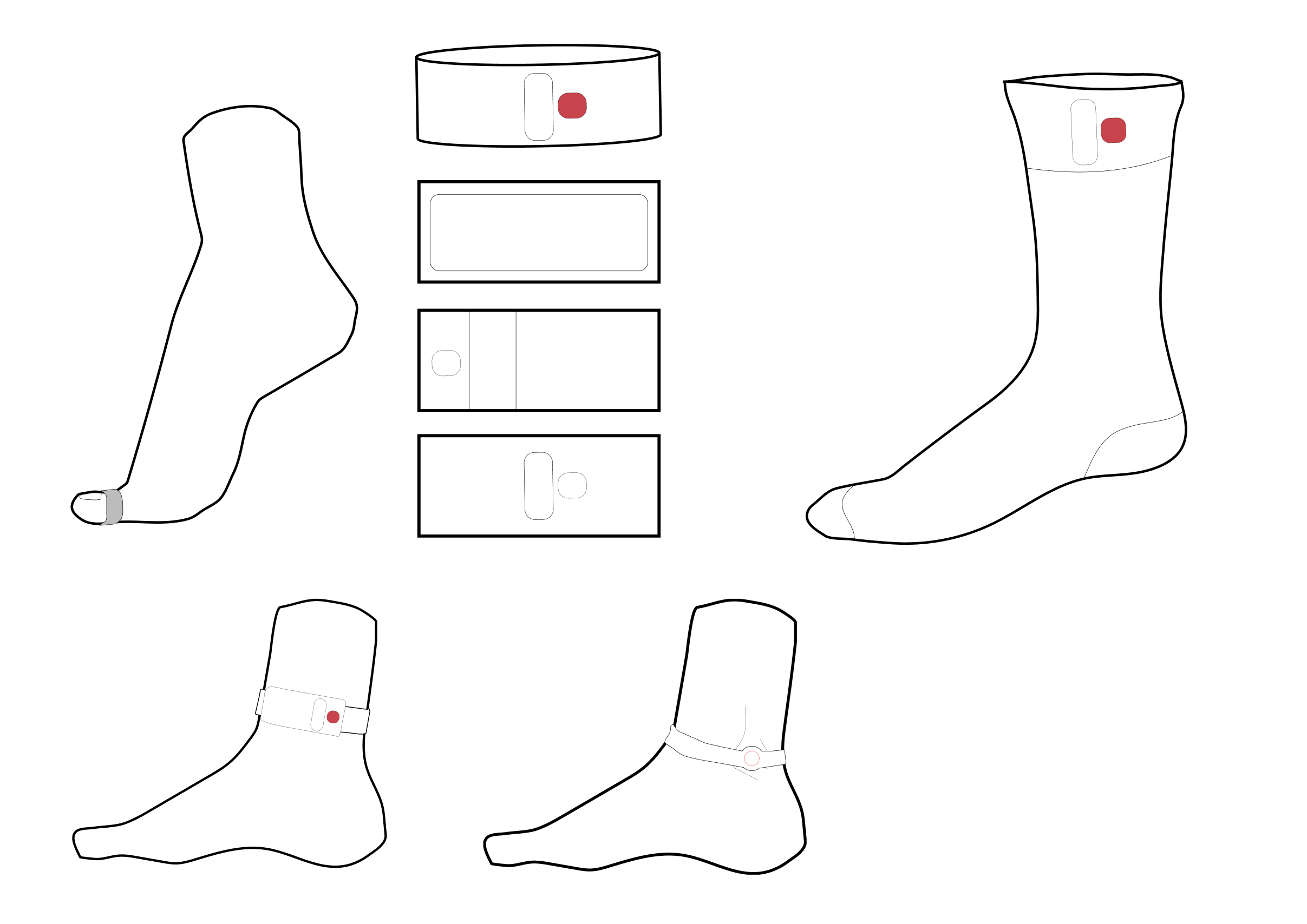
These are quick iterations of what the device could have looked like when I was still doing a wearable device.
Before starting on the code in TinkerCad, I struggled to grasp all the components of my device, because I kept overcomplicating it. So, I went to Zach for advice and he suggested creating a state map, which was extremely helpful in organizing my idea!
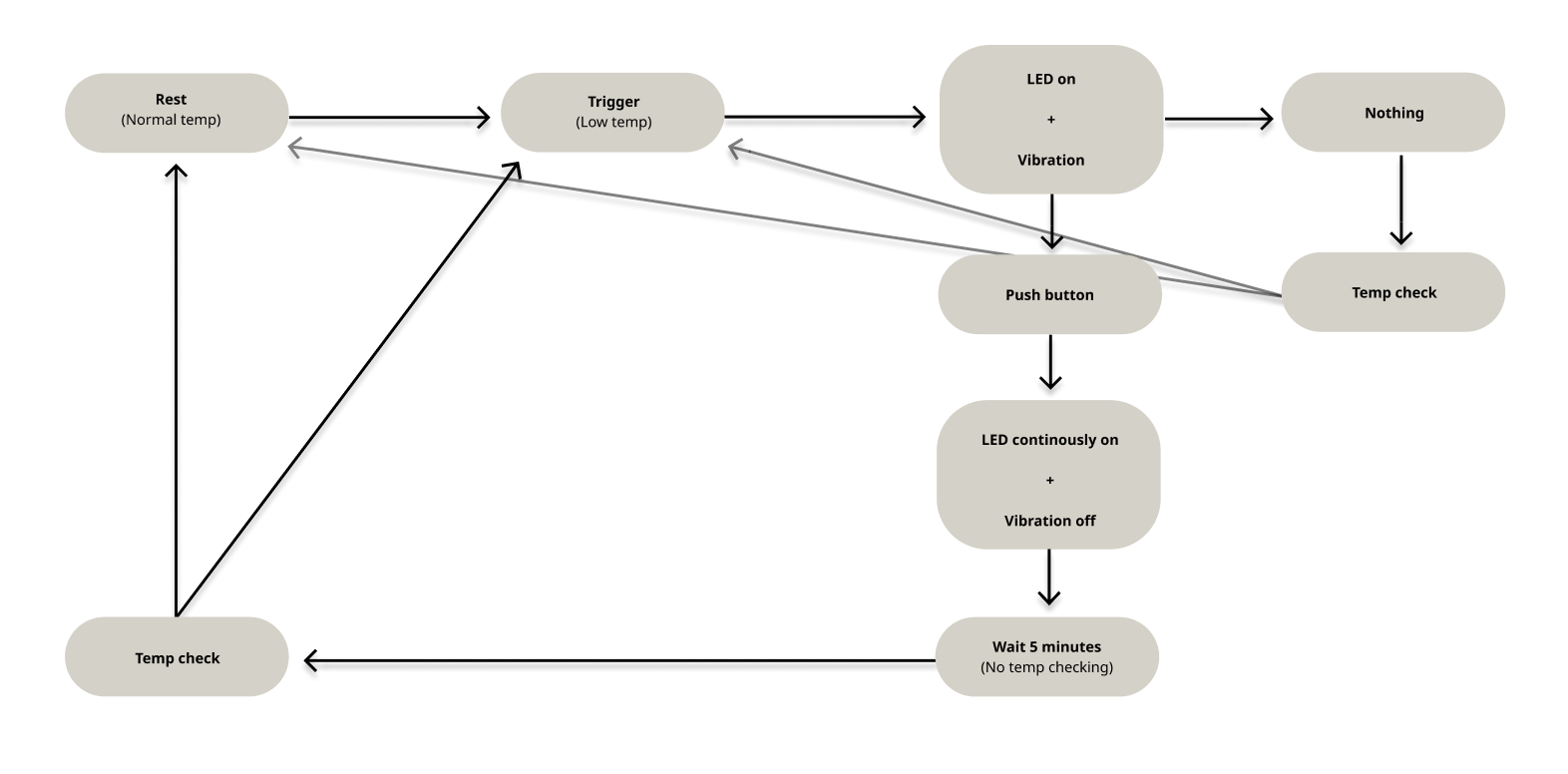
Here is my state map to help me organize what components are needed for my device and what they do.
However, after starting with TinkerCad to get the software aspect of my device working, I realized that I was not competent enough to learn how to use an ATTiny 85. It was difficult for me to code as that type of component does not have a serial monitor for me to check my data. Due to that constraint, I decided to pivot to make a foot stool so that I could use the Arduino Uno. I made the decision to switch because I felt much more comfortable with using the Arduino because of my previous experience. Once I was able to get that all decided, I went to TinkerCad to get that all set up, because I am the most weak with coding.
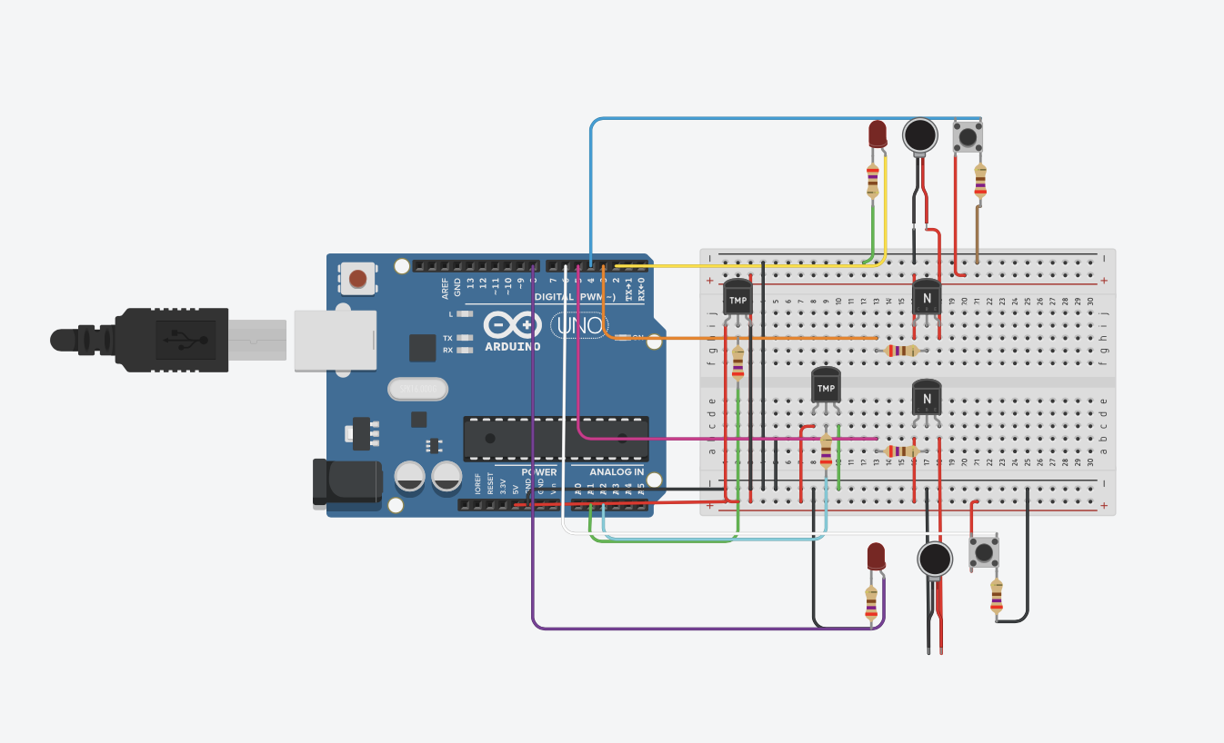
This is the TinkerCad prototype to help me first understand the software aspect of how to create this device. Press on the image to go to the actual TinkerCad Link!
At first, when the temp went into the resting that, there would be weird buffer and then the triggers would turn off. I thought it was a code error at first and went through, but after discussing with Zach, the order of my code was incorrect. To make the code properly articulate what I want the Arduino to do, I need to order it based on sense, decide, do, and then report. After fixing that issue, I had no issues with the TinkerCad!
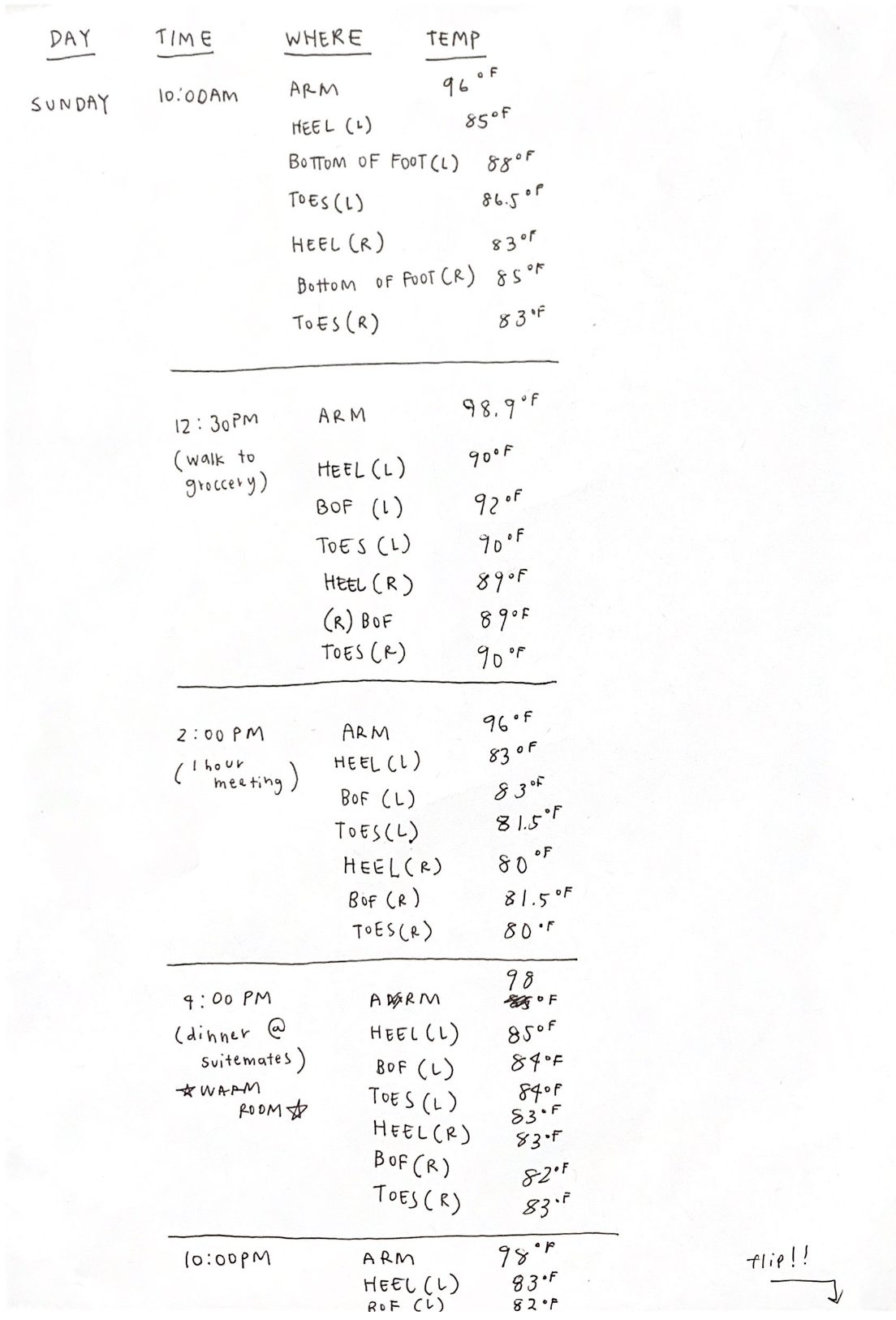
Here is the half of the first day that I did with tracking!
Before fabricating, I wanted to get some data about my personal blood circulation and its correlation with temperature. In order to do so, I tracked the temperature of my feet for a little less than 5 days. I measured my right arm, heels of both feet, bottom of both feet, and big toes of both feet. It was interesting to see the correlation and difference of what I had thought and what was actually true.
One thing that I noticed was that my left foot was always slightly warmer than my right. It was not drastic, but a few degrees. In addition, when the temperature of my feet started to hit around 24 C, then the temperature would continue to drop drastically. Because of that finding, I made my code have anything less than or equal to 24 C as the trigger state. I had fun tracking! I hypothesized that the bottom of my feet and my toes would be the coldest and the heels wouldn’t matter, but as I tracked, it was interesting to see that the heels get cold and sometimes are the coldest areas of my feet.
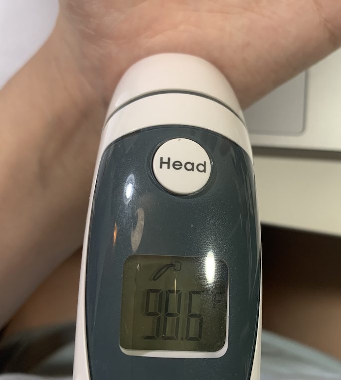
Throughout this project, I used the thermometer that my mom gave me. This was the most I had ever used it!
Now to fabrication! Before I went into the physical building, I wanted to make sure I had an idea of what the foot stool would look like, so I made quick sketches. In addition, I used boxes that I had and used them as bases and pieces.
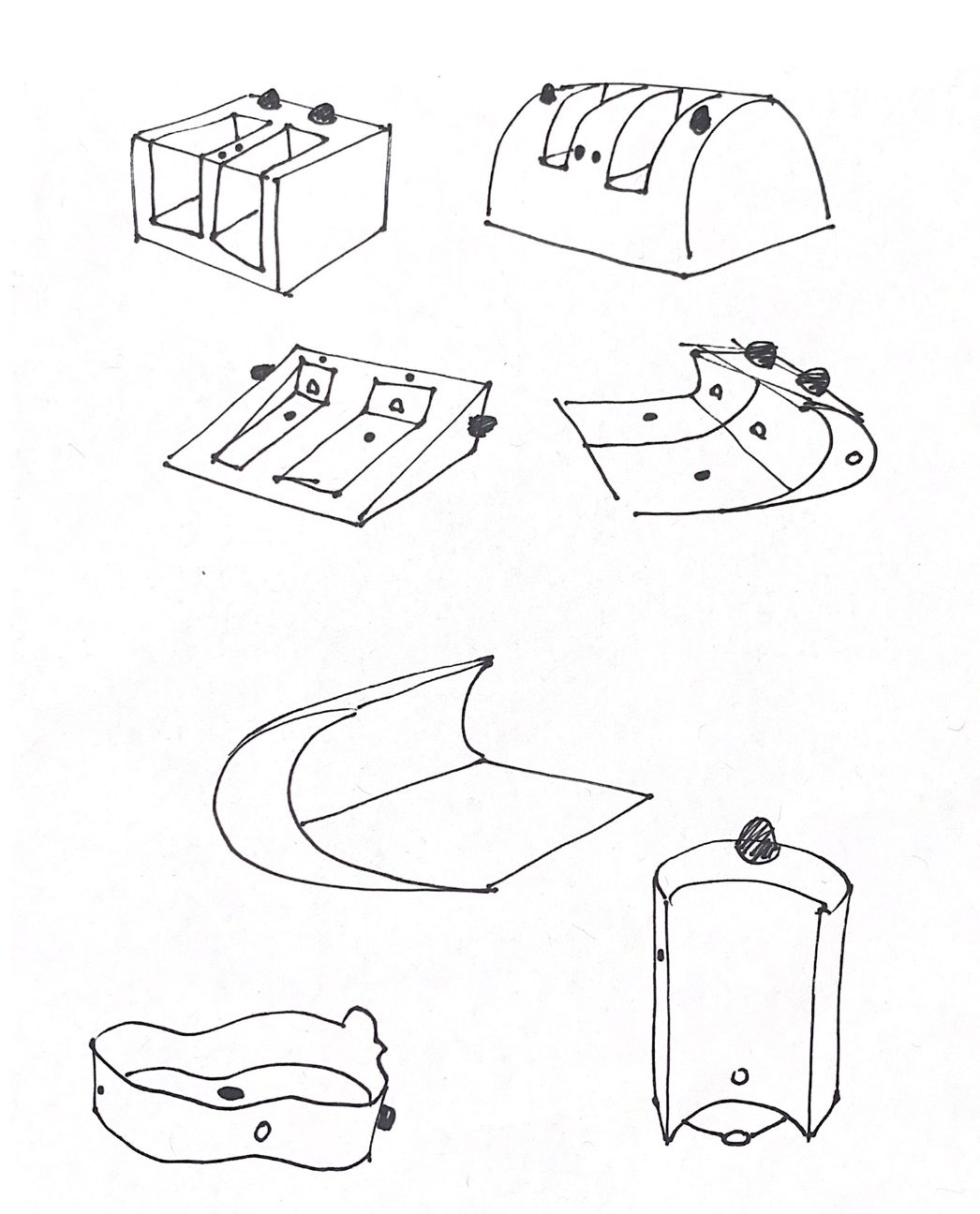
Here are some quick sketches that I made about the design of the foot stool.
At first, I wanted to use as little breadboards as possible, because I thought that would make the process easier. However, I was completely wrong. Limiting myself made it much more difficult when fabricating.
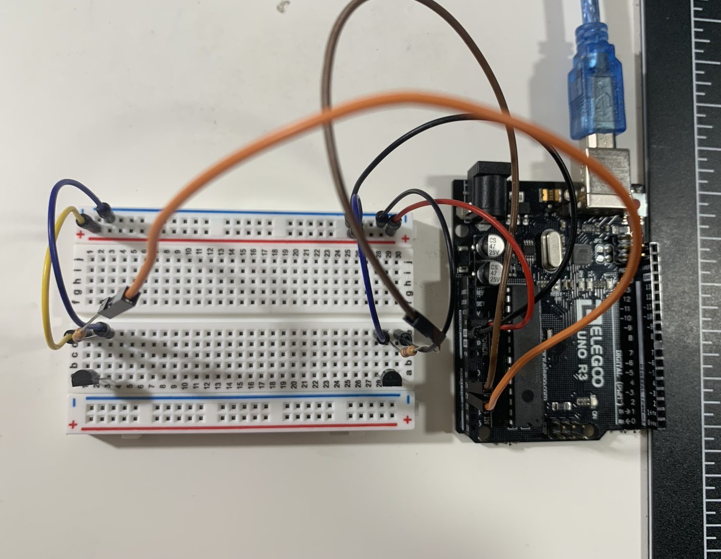
This was my first iteration and I was being ambitious and trying to only use the small breadboard. However, because I had so many components, it would not work.
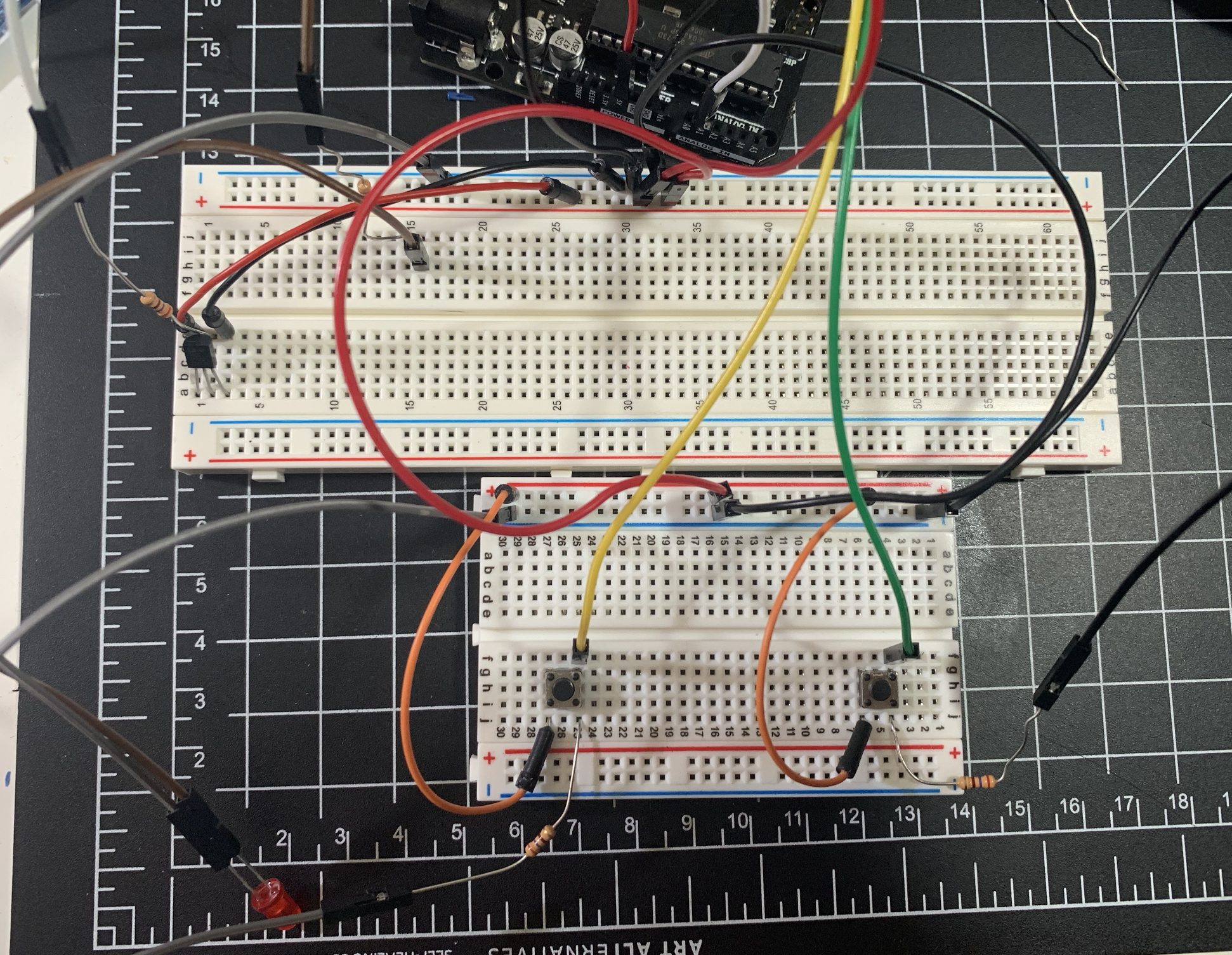
Here is the second trial where I tried only using two bread boards.
After getting most of the components to work with the Arduino, I started to design the foot stool. I used an old smoothie box that I had. For this design, I used my own feet for the sizes. Unfortunately, I was unable to go with this prototype because it would squish the wires, causing poor circuits which I will explain later on.
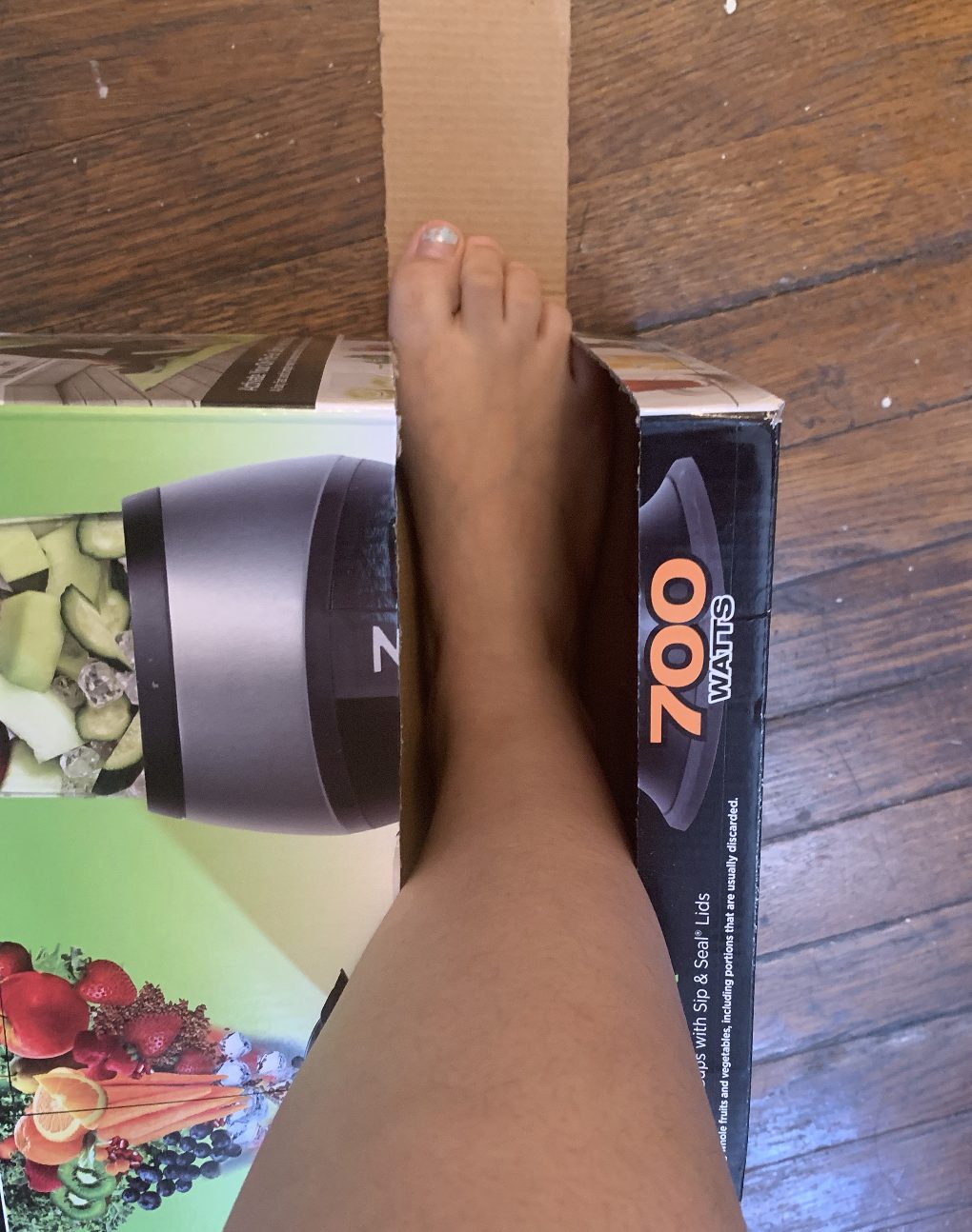
Here is an image of me testing the size of the foot compartment of the stool.
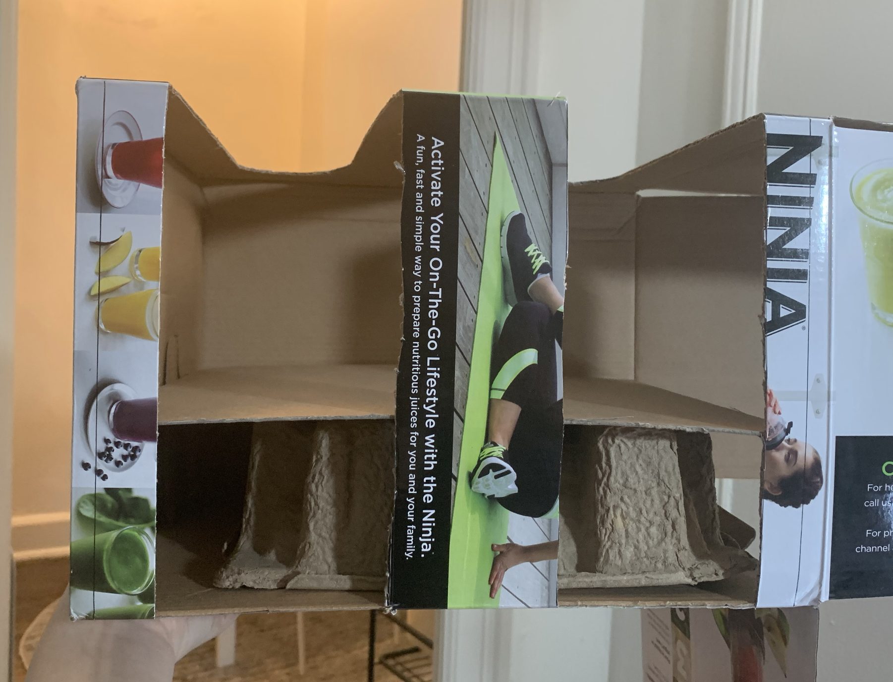
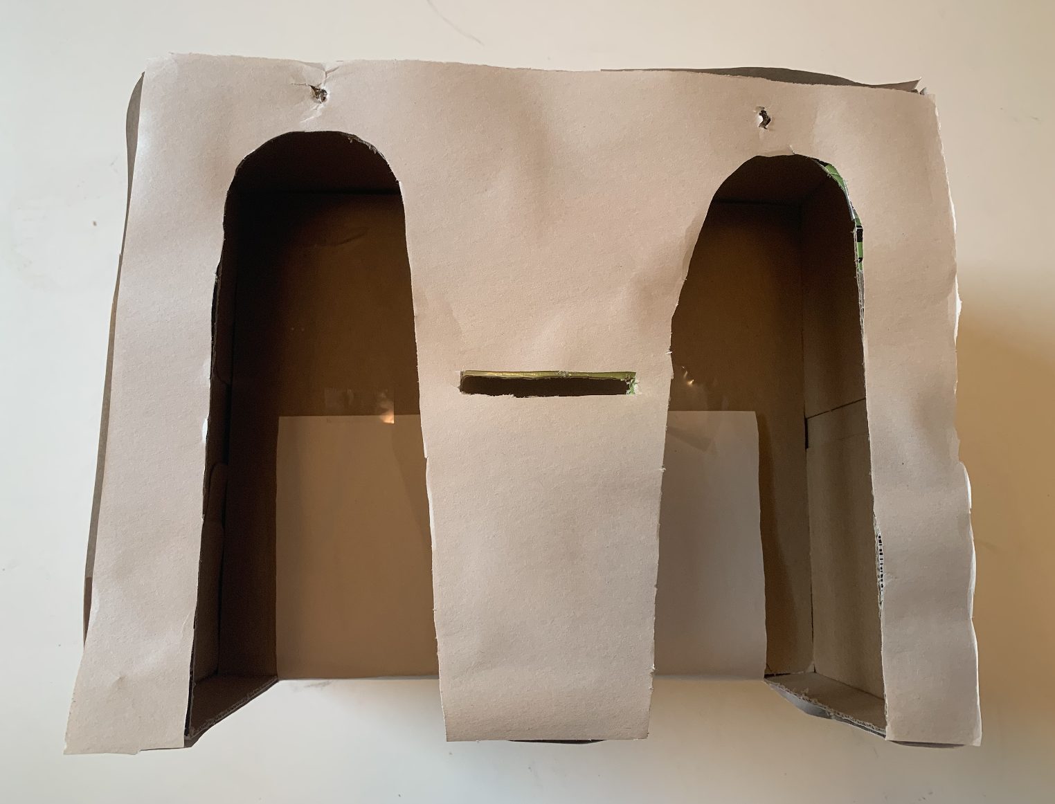
This is an image of the cutout from the front to see the compartments. The box was much taller than I expected so I added a layer on the bottom to make my foot stand slightly higher.
In order for the foot to rest, I made a separate part with the TMP sticking out!
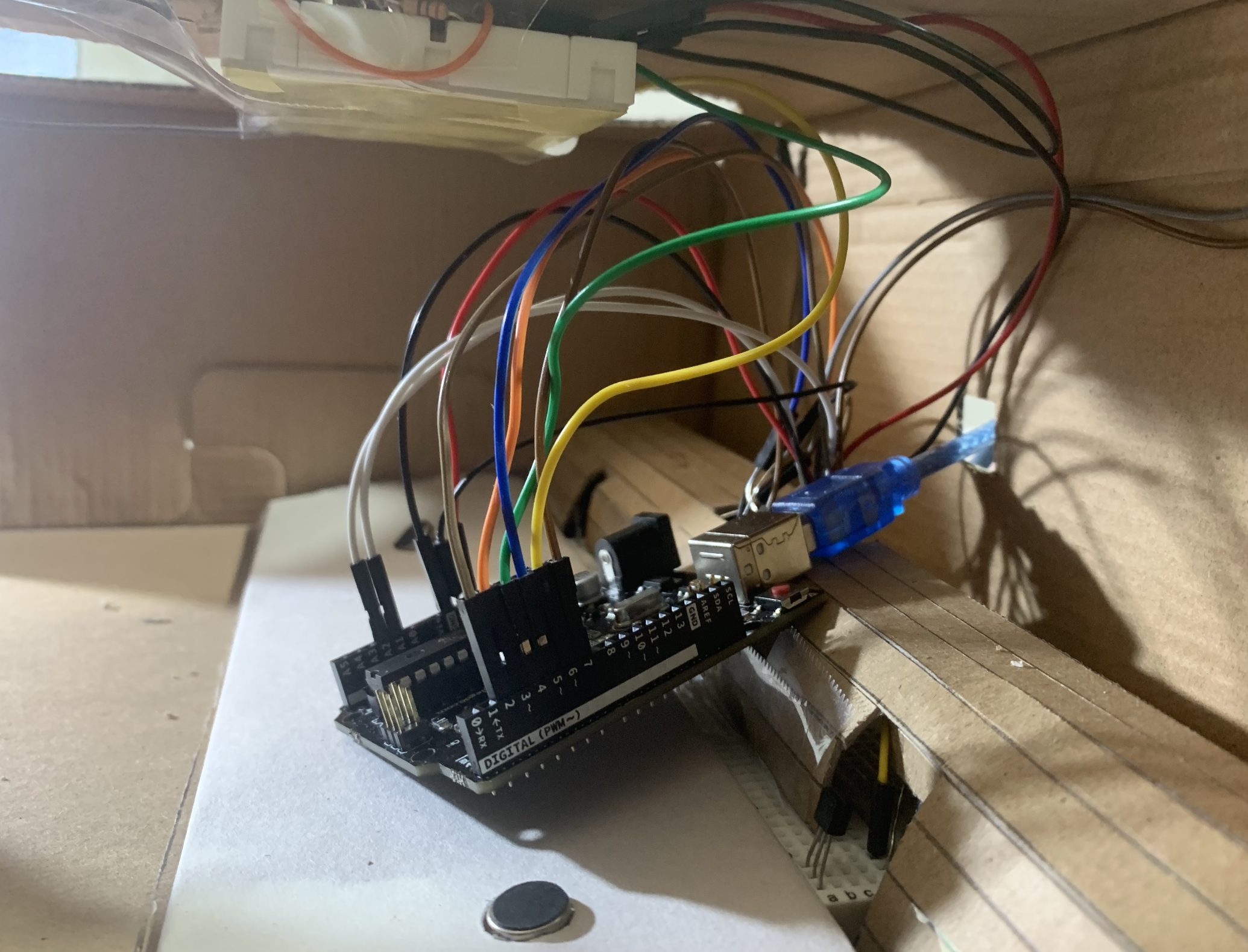
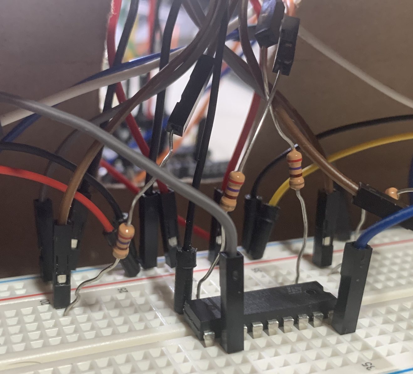
Here is what the wiring looked like from the inside.
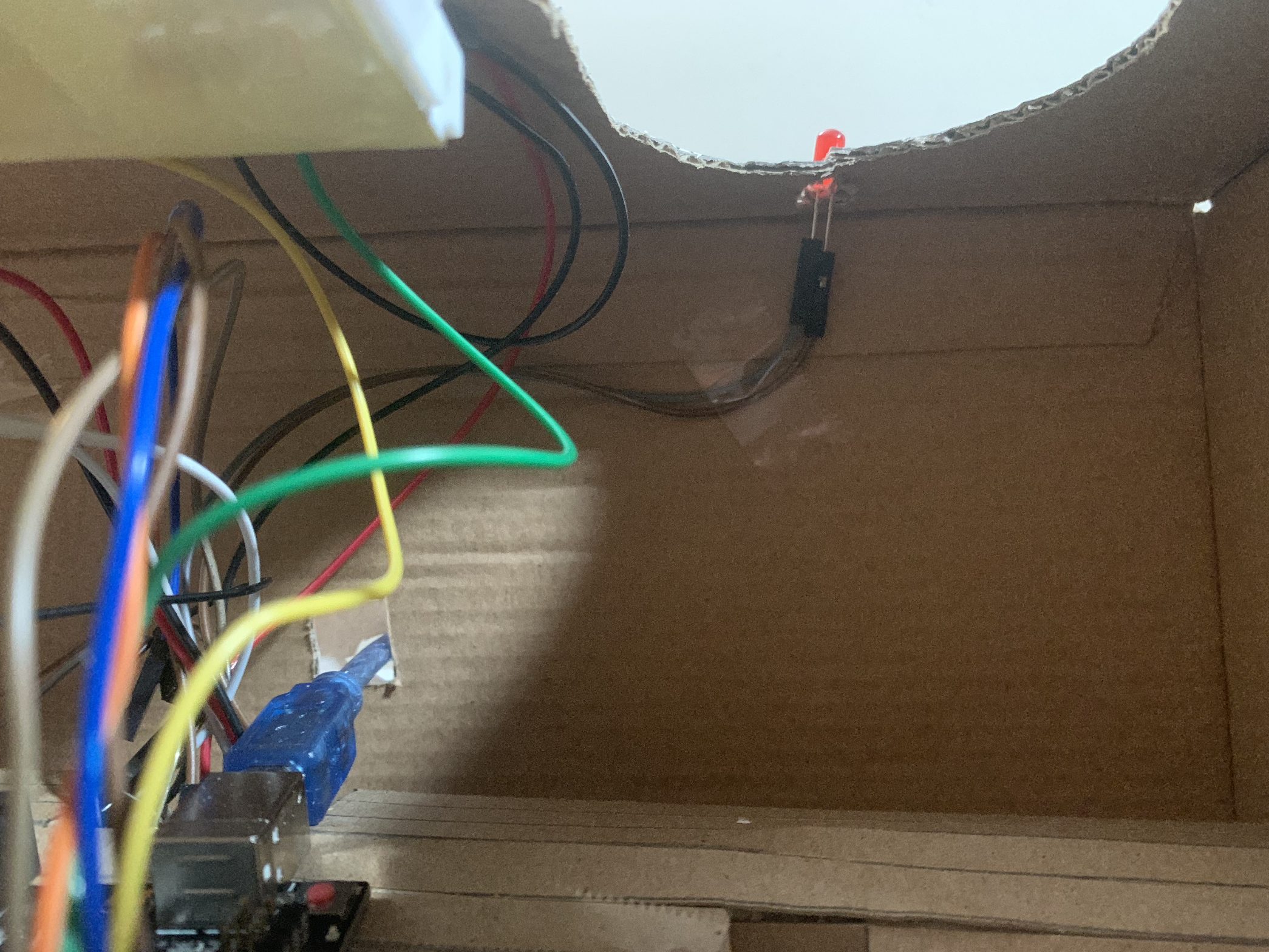
Here is another view of how the LED was placed in this box.
Here is what the hanging metal looked like.
When using this design, it was difficult to use. Before adding my parts into this box, it wasn’t having any major issues, but after I squished it in, then the components were all messed up. There were many issues to why this happened. The main issue was that there were a lot of hanging metal which would touch each other due to the tight space of the box.
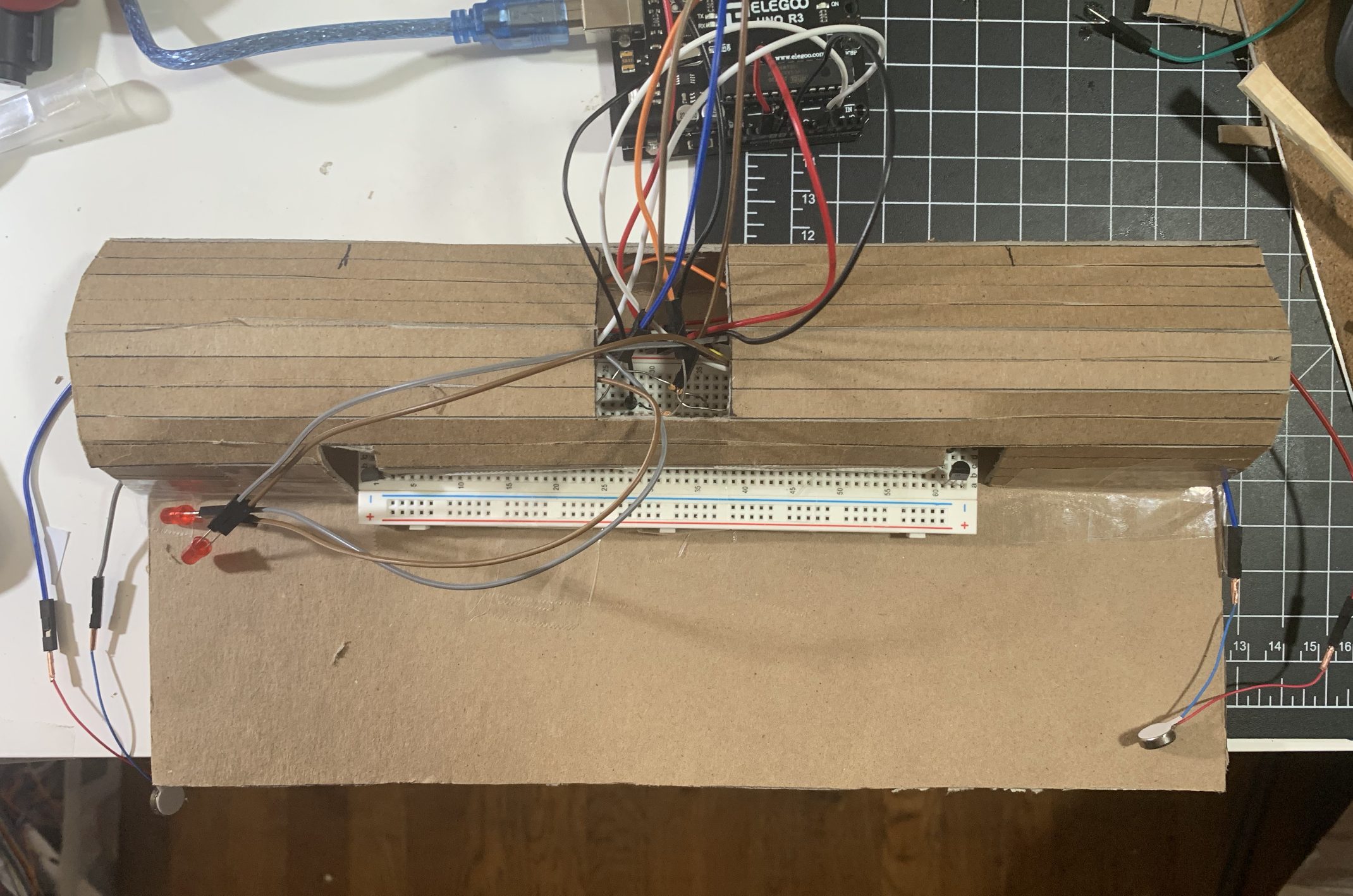
This is what it would have looked like from a birds eye view if I continued on with this design.
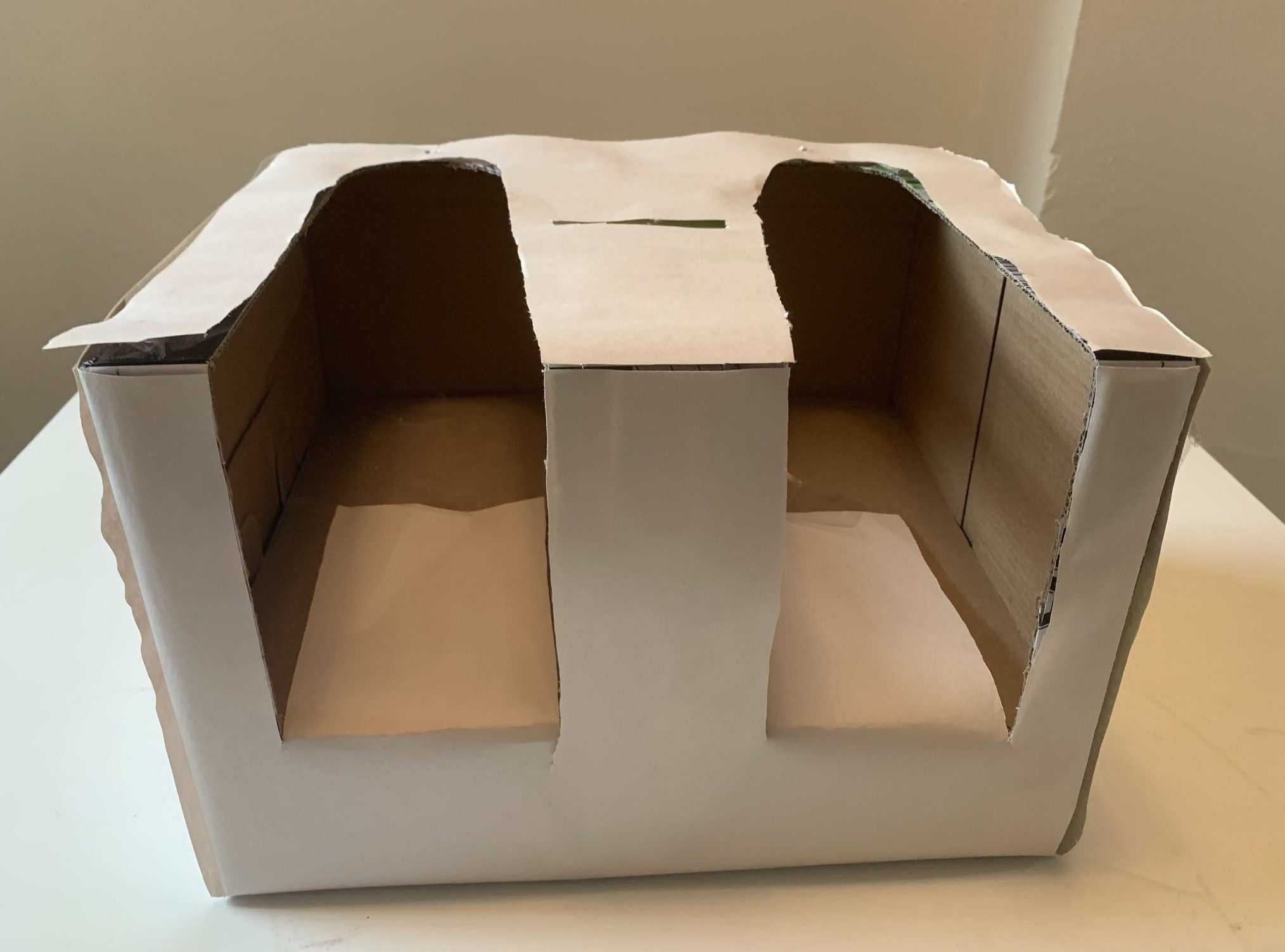
Here is another angle of what the footstool would have looked like in this design.
Here is the quick vector sketch of the newest design.
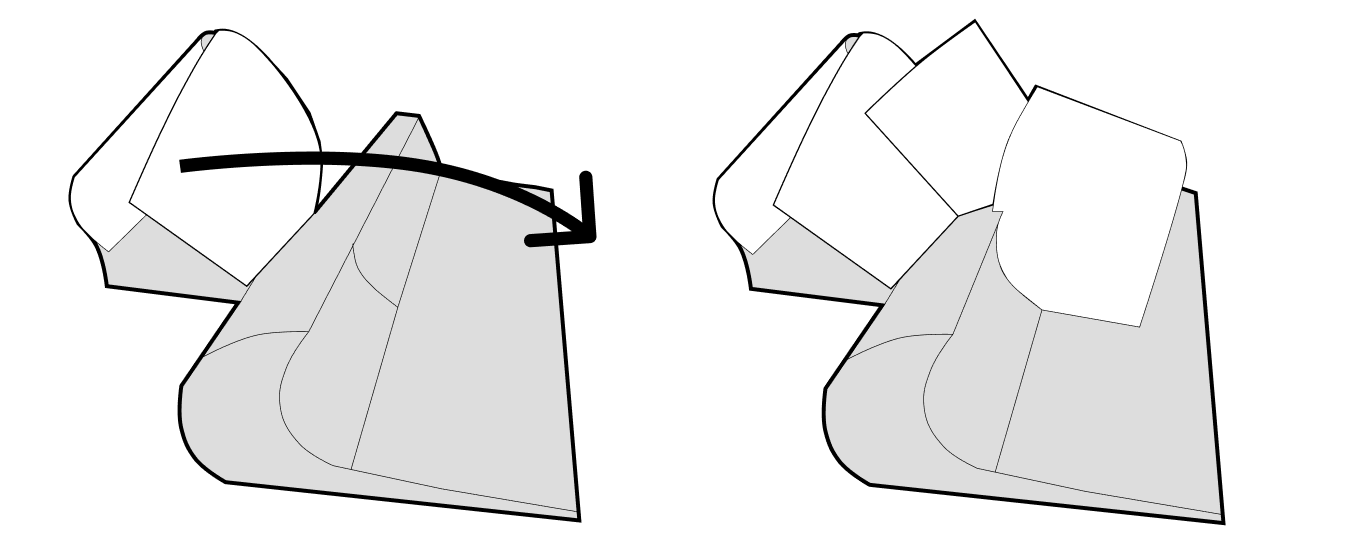
So, after realizing the major issues the previous design had, I wanted to add more breadboards so that there is less potential touching with wires and them getting squished. In addition, I wanted the design to become more flexible so that the wires would not be contained to produce the best circuits. I tried sketching an iteration. Below, you can see how the white parts of the device open and close. Those sections will contain the main breadboards and circuits. It is able to open and close incase there are any issues with the wiring, so that if a user wants to fix it, it is easy to look through.
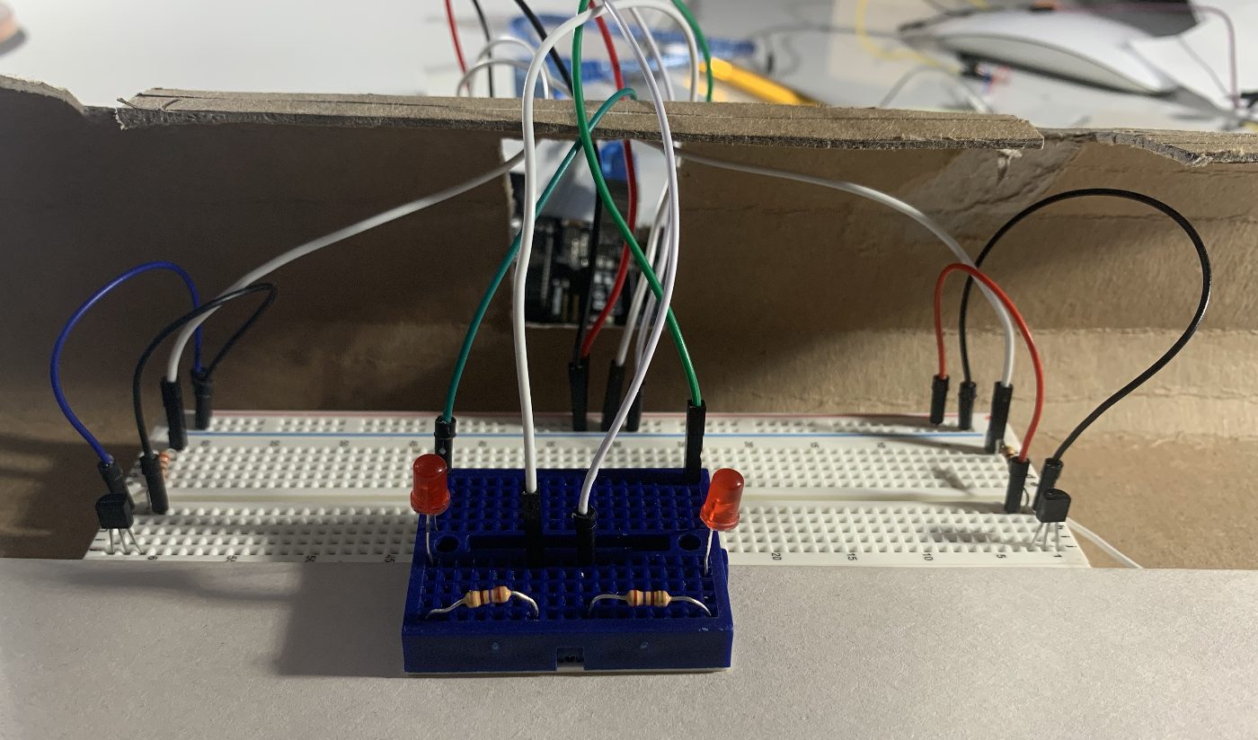
This was the previous circuit where it was only using two breadboards, which was not as effective.
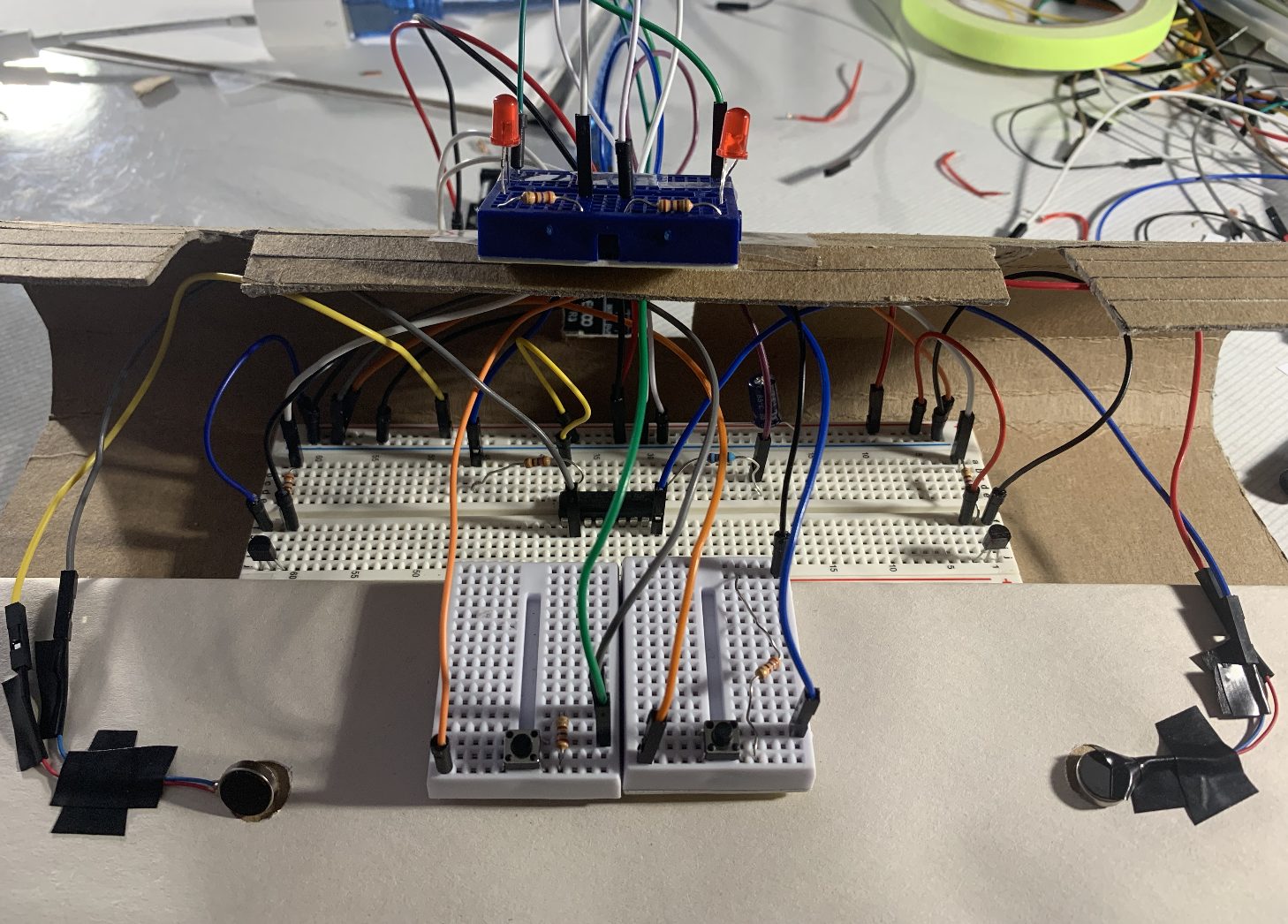
This is the final connections that I made. These circuits were the most effective. I am glad that I used 4 breadboards as it made it much easier to keep track of all the wires as well as keeping them plugged in properly and not squished.

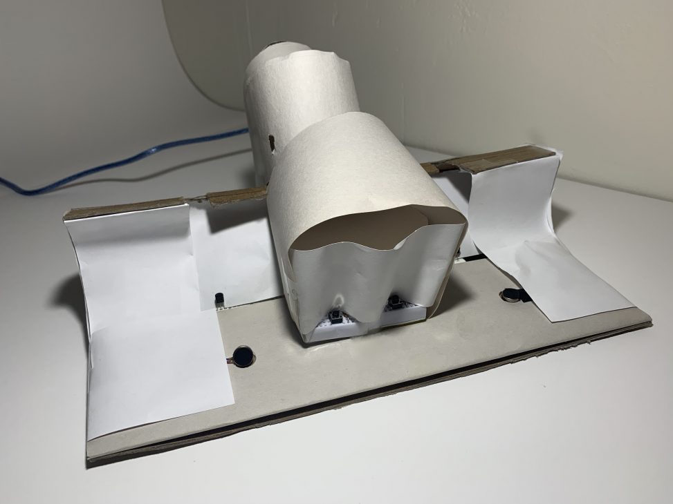
Here is the final product.
Discussion
This project was extremely fun, even though there were a lot of problems in between. Since this was the biggest and most complicated circuit I had built in this class, my process was very all over the place, but I appreciate that. Because of the obstacles, I genuinely feel happy with how far I was able to come with this project. The ideation was definitely not easy, but it really helped me grow overall with my coding, electrical, and mechanical skills. It was not easy, but the problems and solutions that I was able to go through will definitely prepare me for future projects that may be more complex.
How can we use biosignals to create an experience! Temperature and its correlation with blood circulation is a smart way to think! Look into pinching/massaging with bettering the circulation.
This was one of the feedback that stood out to me. I had not thought about ways to better the circulation due to the lack of knowledge with how to help. During the first class check-in, I recall that someone asked if the vibration motor would be used as a way to help circulation, but because it is so light with the shaking it has no affect. Adding on, vibration does not help with increasing heat but rubbing and or massaging does. I think it would be interesting to see what are massage techniques to help blood circulation and then transferring them into motions through motors. I am not sure of how effective and possible that will be in the mechanical side, but it would be extremely interesting to look into in the future. On the other hand, I am not sure if adding this component would take away from the overall purpose of this device being a blood circulation alarm for those who get very busy during the day and forget to move around.
The application seems very relevant. I think the unanswered question for me is how well actual temperature correlates with perceived temperature.
This was the second response that really stuck with me, because the correlation with the actual temperature and perceived temperature is something that I wanted to look more into for next steps. Because the TMP36 is small, it does not accurately get the correct temperature all the time, so I was thinking about having multiple TMP36s all around each foot and then averaging the temperatures to get the most accurate data.
Overall, I think I did a good job and I am happy with the final product. The device works the way that I intended which is what really excites me. In the beginning, I definitely lacked a lot of confidence due to my lack of expertise, but as I worked, I realized that I should not feel that way. This class is meant for me to make mistakes and play around so that I can grow. It was difficult for me to code and do the wirings, but as I kept trying and looking at other projects, I felt really excited cause I would get closer and closer each time. Furthermore, the design of the stool was much harder than I thought it would be. I did not consider that squishing the wires would mess up circulations. From this, I learned how to deal with cutting metal to fit the breadboard without sticking out.
The biggest takeaways from this project was that HANGING WIRES ARE A NO NO. I never knew about hanging metals so I thought that it was normal to have metal in a female/male wire. But through this project, I learned about how wrong that is. In addition, TinkerCAD is not always simulating the circuits properly, so I should try to work on the physical building as soon as possible. Adding on, be gentle with the wires! While I was trying to get the metal from the pancake vibration motor, I accidentally pulled the wire too much and broke it. Lastly, be ready for the unexpected by having back-up plans. No matter how well-planned your project is, there can be obstacles that occur due to anything. I think this project really helped me grow to work smarter. With the previous project and assignments, I struggled to fully get the connections with code, electronics, and mechanics, but with this project, I feel confident with my ability.
For next steps, I would want to try learning how to use the ATTiny to create the anklet version. Also, I would want to reiterate on my final stool design because I used paper for this version which was not as clean as I want. In addition, I want to continue to research how to accurately get data from the TMP36. I say this because I tested out the device while doing homework for an hour. I had not considered some factors that would disrupt my data. One factor is that I shake my right leg when I am sitting down, which made it difficult for the device to accurately get my temperature properly. Adding on, there would be times that I would check the temperature with the thermometer and then the TMP36 and the data would be different. I want to look more into why they are different to make my device get more accurate information.
In the end, I am proud with the overall finish of the project! I was really able to push my comfort level and skills through this project. I think that I am glad that I tried to be ambitious as it was a great way for me to learn more about physical computing on my own and learn how to problem-solve through my comprehension skills and other resources. I am so thankful for everyone who had helped me with this device.
Schematic
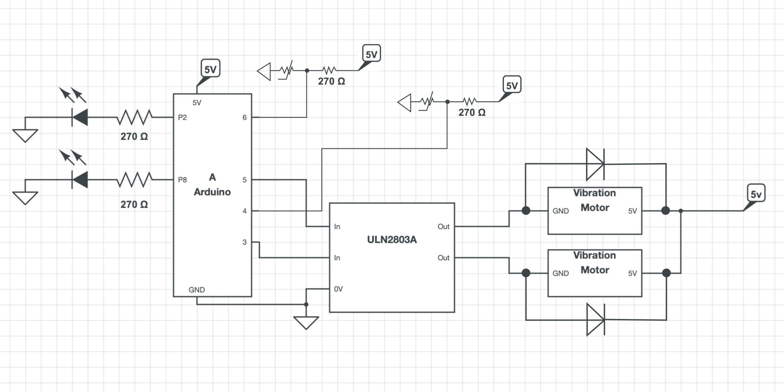
Here is my schematic drawing!
- <span class="com">/*
- * Project 2: An Assistive Device for someone you know well
- * Jina Lee (jinal2)
- *
- * Collaboration: For this project, I used various resources
- * to help me get to the final state! Due to my lack of
- * experience with everything (software, electrical, and
- * fabrication), it was extremely helpful for me to do
- * research and see what other people have done.
- *
- * I worked closely with my professor, Zach, to get a better
- * understanding of how to use a ULN2803A, properly order my
- * code, plug in wires without metals touching each other on
- * the breadboard, and use multiple breadboards. Without the
- * help of Zach, my project would not have been able to be at
- * the final state, because he drastically aided me in fully
- * understanding software and electrical concepts which I
- * struggled a lot with!
- *
- * https://www.tinkercad.com/things/7KlkHaxx20c-
- * tmp36-temperature-sensor-with-arduino
- * zhtuhin4: For learning what formulas are needed to find the
- * temperature from the voltage that the TMP is getting.
- *
- * https://learn.adafruit.com/tmp36-temperature-sensor/
- * using-a-temp-sensor
- * This link was used to help me learn how to properly use the
- * temperature sensor. Because of my inexperience, looking at
- * the formulas and various types of way to approach the software
- * was extremely helpful.
- *
- * https://bc-robotics.com/tutorials/using-a-tmp36-temperature-
- * sensor-with-arduino/
- * This link helped me by going step by step on how to use the
- * TMP36 sensor with the Arduino by showing images and code to
- * explain the steps. The way this website explained to me was
- * the most effective in getting me to fully understand what
- * to do!
- *
- * https://dothemath.ucsd.edu/2012/04/heat-those-feet/
- * This article is about cold feet and how to treat them. This
- * reading was helpful to me so that I have a strong understanding
- * of how I can correlate the temperature of my feet to blood
- * circulation.
- *
- * https://pubmed.ncbi.nlm.nih.gov/20660876/
- * This paper is about how foot temperature can also be affected
- * by age. It was interesting to see the correlation about peoples'
- * feet temperatures while sleeping. My feet are usually extremely
- * cold when I am about to go to sleep, but when I wake up, they
- * are warm.
- *
- * Sue Lee: Former student in this class, helped me when I had
- * trouble with fabrication. There was an issue with the TMP36
- * getting negative degrees and she suggested to change the GND and
- * 5V to switch the current, which is what works with motors.
- * However, after trying that, thankfully the arduino and all my
- * components were completely fine, but the TMP36 heat up really
- * quickly, so I had to not touch my stuff for a few minutes.
- *
- * Description:
- * The code below uses the temperature sensors to detect the blood
- * circulation in user's feet. When the trigger tempt is detected
- * (anything less than 29 C), then the LEDs and Vibration motors
- * will turn on. In that trigger state, if the push button is pressed,
- * then the TMP36 that is connected to it will take a five minute
- * wait, giving the person time to move around to raise their tempt.
- * During the wait time, the LED stays on while the vibration stops.
- * After the wait time is up, then the temperature will detect again
- * and if it is in the resting state, the device will stop all
- * triggers. However, if it is the opposite, both triggers will
- * start again.
- *
- * Pin mapping:
- * pin | mode | description
- * ----|------|------------
- * A1 |INPUT | TMP36 Sensor
- * A2 |INPUT | TMP36 Sensor
- * 2 |OUTPUT| LED
- * 3 |OUTPUT| Pancake Vibration Motor
- * 4 |INPUT | Pushbutton
- * 5 |OUTPUT| Pancake Vibration Motor
- * 6 |INPUT | Pushbutton
- * 8 |OUTPUT| LED
- */</span><span class="pln">
- </span><span class="kwd">const</span><span class="pln"> </span><span class="kwd">int</span><span class="pln"> lefttemperaturePin </span><span class="pun">=</span><span class="pln"> A1</span><span class="pun">;</span><span class="pln">
- </span><span class="kwd">const</span><span class="pln"> </span><span class="kwd">int</span><span class="pln"> righttemperaturePin </span><span class="pun">=</span><span class="pln"> A2</span><span class="pun">;</span><span class="pln">
- </span><span class="kwd">const</span><span class="pln"> </span><span class="kwd">int</span><span class="pln"> leftLED </span><span class="pun">=</span><span class="pln"> </span><span class="lit">2</span><span class="pun">;</span><span class="pln">
- </span><span class="kwd">const</span><span class="pln"> </span><span class="kwd">int</span><span class="pln"> rightLED </span><span class="pun">=</span><span class="pln"> </span><span class="lit">8</span><span class="pun">;</span><span class="pln">
- </span><span class="kwd">const</span><span class="pln"> </span><span class="kwd">int</span><span class="pln"> leftMOTOR </span><span class="pun">=</span><span class="pln"> </span><span class="lit">3</span><span class="pun">;</span><span class="pln">
- </span><span class="kwd">const</span><span class="pln"> </span><span class="kwd">int</span><span class="pln"> rightMOTOR </span><span class="pun">=</span><span class="pln"> </span><span class="lit">5</span><span class="pun">;</span><span class="pln">
- </span><span class="kwd">const</span><span class="pln"> </span><span class="kwd">int</span><span class="pln"> leftBUTTON </span><span class="pun">=</span><span class="pln"> </span><span class="lit">4</span><span class="pun">;</span><span class="pln">
- </span><span class="kwd">const</span><span class="pln"> </span><span class="kwd">int</span><span class="pln"> rightBUTTON </span><span class="pun">=</span><span class="pln"> </span><span class="lit">6</span><span class="pun">;</span><span class="pln">
- </span><span class="kwd">void</span><span class="pln"> setup</span><span class="pun">()</span><span class="pln">
- </span><span class="pun">{</span><span class="pln">
- pinMode</span><span class="pun">(</span><span class="pln">lefttemperaturePin</span><span class="pun">,</span><span class="pln"> INPUT</span><span class="pun">);</span><span class="pln">
- pinMode</span><span class="pun">(</span><span class="pln">righttemperaturePin</span><span class="pun">,</span><span class="pln"> INPUT</span><span class="pun">);</span><span class="pln">
- pinMode</span><span class="pun">(</span><span class="pln">leftBUTTON</span><span class="pun">,</span><span class="pln"> INPUT</span><span class="pun">);</span><span class="pln">
- pinMode</span><span class="pun">(</span><span class="pln">rightBUTTON</span><span class="pun">,</span><span class="pln"> INPUT</span><span class="pun">);</span><span class="pln">
- pinMode</span><span class="pun">(</span><span class="pln">leftLED</span><span class="pun">,</span><span class="pln"> OUTPUT</span><span class="pun">);</span><span class="pln">
- pinMode</span><span class="pun">(</span><span class="pln">rightLED</span><span class="pun">,</span><span class="pln"> OUTPUT</span><span class="pun">);</span><span class="pln">
- pinMode</span><span class="pun">(</span><span class="pln">leftMOTOR</span><span class="pun">,</span><span class="pln"> OUTPUT</span><span class="pun">);</span><span class="pln">
- pinMode</span><span class="pun">(</span><span class="pln">rightMOTOR</span><span class="pun">,</span><span class="pln"> OUTPUT</span><span class="pun">);</span><span class="pln">
- </span><span class="typ">Serial</span><span class="pun">.</span><span class="kwd">begin</span><span class="pun">(</span><span class="lit">9600</span><span class="pun">);</span><span class="pln">
- </span><span class="pun">}</span><span class="pln">
- </span><span class="kwd">void</span><span class="pln"> loop</span><span class="pun">()</span><span class="pln">
- </span><span class="pun">{</span><span class="pln">
- </span><span class="kwd">float</span><span class="pln"> lvoltage</span><span class="pun">,</span><span class="pln"> ldegreesC</span><span class="pun">,</span><span class="pln"> ldegreesF</span><span class="pun">;</span><span class="pln">
- </span><span class="kwd">float</span><span class="pln"> rvoltage</span><span class="pun">,</span><span class="pln"> rdegreesC</span><span class="pun">,</span><span class="pln"> rdegreesF</span><span class="pun">;</span><span class="pln">
- </span><span class="kwd">int</span><span class="pln"> leftbuttonState </span><span class="pun">=</span><span class="pln"> digitalRead</span><span class="pun">(</span><span class="pln">leftBUTTON</span><span class="pun">);</span><span class="pln">
- </span><span class="kwd">int</span><span class="pln"> rightbuttonState </span><span class="pun">=</span><span class="pln"> digitalRead</span><span class="pun">(</span><span class="pln">rightBUTTON</span><span class="pun">);</span><span class="pln">
- </span><span class="com">//Measure left foot voltage</span><span class="pln">
- lvoltage </span><span class="pun">=</span><span class="pln"> getVoltage</span><span class="pun">(</span><span class="pln">lefttemperaturePin</span><span class="pun">);</span><span class="pln">
- </span><span class="com">//Convert left voltage to degrees Celsius</span><span class="pln">
- ldegreesC </span><span class="pun">=</span><span class="pln"> </span><span class="pun">(</span><span class="pln">lvoltage </span><span class="pun">-</span><span class="pln"> </span><span class="lit">0.5</span><span class="pun">)</span><span class="pln"> </span><span class="pun">*</span><span class="pln"> </span><span class="lit">100.0</span><span class="pun">;</span><span class="pln">
- </span><span class="com">//Convert left Celsius to Fahrenheit</span><span class="pln">
- ldegreesF </span><span class="pun">=</span><span class="pln"> ldegreesC </span><span class="pun">*</span><span class="pln"> </span><span class="pun">(</span><span class="lit">9.0</span><span class="pun">/</span><span class="lit">5.0</span><span class="pun">)</span><span class="pln"> </span><span class="pun">+</span><span class="pln"> </span><span class="lit">32.0</span><span class="pun">;</span><span class="pln">
- </span><span class="com">//Measure right foot voltage </span><span class="pln">
- rvoltage </span><span class="pun">=</span><span class="pln"> getVoltage</span><span class="pun">(</span><span class="pln">righttemperaturePin</span><span class="pun">);</span><span class="pln">
- </span><span class="com">//Convert right voltage to degrees Celsius</span><span class="pln">
- rdegreesC </span><span class="pun">=</span><span class="pln"> </span><span class="pun">(</span><span class="pln">rvoltage </span><span class="pun">-</span><span class="pln"> </span><span class="lit">0.5</span><span class="pun">)</span><span class="pln"> </span><span class="pun">*</span><span class="pln"> </span><span class="lit">100.0</span><span class="pun">;</span><span class="pln">
- </span><span class="com">//Convert right Celsius to Fahrenheit</span><span class="pln">
- rdegreesF </span><span class="pun">=</span><span class="pln"> rdegreesC </span><span class="pun">*</span><span class="pln"> </span><span class="pun">(</span><span class="lit">9.0</span><span class="pun">/</span><span class="lit">5.0</span><span class="pun">)</span><span class="pln"> </span><span class="pun">+</span><span class="pln"> </span><span class="lit">32.0</span><span class="pun">;</span><span class="pln">
- </span><span class="com">//When the left temp is lower than the resting state</span><span class="pln">
- </span><span class="com">//and the button is pushed,</span><span class="pln">
- </span><span class="com">//then there is a five minute pause.</span><span class="pln">
- </span><span class="com">//The vibration turns off, but the LED is still </span><span class="pln">
- </span><span class="com">//on to notify users what state it is in.</span><span class="pln">
- </span><span class="com">//Afterwards, the left temp is checked again.</span><span class="pln">
- </span><span class="com">//If it is still lower than the resting state,</span><span class="pln">
- </span><span class="com">//then the trigger starts until left temp moves up</span><span class="pln">
- </span><span class="kwd">if</span><span class="pln"> </span><span class="pun">((</span><span class="pln">leftbuttonState </span><span class="pun">==</span><span class="pln"> HIGH</span><span class="pun">))</span><span class="pln"> </span><span class="pun">{</span><span class="pln">
- digitalWrite</span><span class="pun">(</span><span class="pln">leftLED</span><span class="pun">,</span><span class="pln"> HIGH</span><span class="pun">);</span><span class="pln">
- digitalWrite</span><span class="pun">(</span><span class="pln">leftMOTOR</span><span class="pun">,</span><span class="pln"> LOW</span><span class="pun">);</span><span class="pln">
- </span><span class="com">//Wait for the user to move around (right now</span><span class="pln">
- </span><span class="com">//using a faster time to display the task)</span><span class="pln">
- delay</span><span class="pun">(</span><span class="lit">5000</span><span class="pun">);</span><span class="pln">
- </span><span class="com">//Measure left foot voltage again when </span><span class="pln">
- </span><span class="com">//button is pushed</span><span class="pln">
- lvoltage </span><span class="pun">=</span><span class="pln"> getVoltage</span><span class="pun">(</span><span class="pln">lefttemperaturePin</span><span class="pun">);</span><span class="pln">
- ldegreesC </span><span class="pun">=</span><span class="pln"> </span><span class="pun">(</span><span class="pln">lvoltage </span><span class="pun">-</span><span class="pln"> </span><span class="lit">0.5</span><span class="pun">)</span><span class="pln"> </span><span class="pun">*</span><span class="pln"> </span><span class="lit">100.0</span><span class="pun">;</span><span class="pln">
- ldegreesF </span><span class="pun">=</span><span class="pln"> ldegreesC </span><span class="pun">*</span><span class="pln"> </span><span class="pun">(</span><span class="lit">9.0</span><span class="pun">/</span><span class="lit">5.0</span><span class="pun">)</span><span class="pln"> </span><span class="pun">+</span><span class="pln"> </span><span class="lit">32.0</span><span class="pun">;</span><span class="pln">
- </span><span class="kwd">if</span><span class="pln"> </span><span class="pun">(</span><span class="pln">ldegreesC </span><span class="pun">></span><span class="pln"> </span><span class="lit">29</span><span class="pun">)</span><span class="pln"> </span><span class="pun">{</span><span class="pln">
- </span><span class="com">//Measure left foot voltage after the delay</span><span class="pln">
- lvoltage </span><span class="pun">=</span><span class="pln"> getVoltage</span><span class="pun">(</span><span class="pln">lefttemperaturePin</span><span class="pun">);</span><span class="pln">
- ldegreesC </span><span class="pun">=</span><span class="pln"> </span><span class="pun">(</span><span class="pln">lvoltage </span><span class="pun">-</span><span class="pln"> </span><span class="lit">0.5</span><span class="pun">)</span><span class="pln"> </span><span class="pun">*</span><span class="pln"> </span><span class="lit">100.0</span><span class="pun">;</span><span class="pln">
- ldegreesF </span><span class="pun">=</span><span class="pln"> ldegreesC </span><span class="pun">*</span><span class="pln"> </span><span class="pun">(</span><span class="lit">9.0</span><span class="pun">/</span><span class="lit">5.0</span><span class="pun">)</span><span class="pln"> </span><span class="pun">+</span><span class="pln"> </span><span class="lit">32.0</span><span class="pun">;</span><span class="pln">
- </span><span class="com">//If tempt is in resting state,</span><span class="pln">
- </span><span class="com">//then the triggers turn off</span><span class="pln">
- digitalWrite</span><span class="pun">(</span><span class="pln">leftLED</span><span class="pun">,</span><span class="pln"> LOW</span><span class="pun">);</span><span class="pln">
- digitalWrite</span><span class="pun">(</span><span class="pln">leftMOTOR</span><span class="pun">,</span><span class="pln"> LOW</span><span class="pun">);</span><span class="pln">
- delay</span><span class="pun">(</span><span class="lit">10</span><span class="pun">);</span><span class="pln">
- </span><span class="pun">}</span><span class="pln"> </span><span class="kwd">else</span><span class="pln"> </span><span class="pun">{</span><span class="pln">
- </span><span class="com">//If tempt is still in trigger state,</span><span class="pln">
- </span><span class="com">//then the triggers continue</span><span class="pln">
- digitalWrite</span><span class="pun">(</span><span class="pln">leftLED</span><span class="pun">,</span><span class="pln"> HIGH</span><span class="pun">);</span><span class="pln">
- digitalWrite</span><span class="pun">(</span><span class="pln">leftMOTOR</span><span class="pun">,</span><span class="pln"> HIGH</span><span class="pun">);</span><span class="pln">
- delay</span><span class="pun">(</span><span class="lit">10</span><span class="pun">);</span><span class="pln">
- </span><span class="pun">}</span><span class="pln">
- </span><span class="pun">}</span><span class="pln">
- </span><span class="com">//When left temp is lower than the resting state</span><span class="pln">
- </span><span class="com">//the tiggers start</span><span class="pln">
- </span><span class="kwd">if</span><span class="pln"> </span><span class="pun">(</span><span class="pln">ldegreesC </span><span class="pun"><</span><span class="pln"> </span><span class="lit">29</span><span class="pun">)</span><span class="pln"> </span><span class="pun">{</span><span class="pln">
- digitalWrite</span><span class="pun">(</span><span class="pln">leftLED</span><span class="pun">,</span><span class="pln"> HIGH</span><span class="pun">);</span><span class="pln">
- digitalWrite</span><span class="pun">(</span><span class="pln">leftMOTOR</span><span class="pun">,</span><span class="pln"> HIGH</span><span class="pun">);</span><span class="pln">
- delay</span><span class="pun">(</span><span class="lit">10</span><span class="pun">);</span><span class="pln">
- </span><span class="pun">}</span><span class="pln"> </span><span class="kwd">else</span><span class="pln"> </span><span class="pun">{</span><span class="pln">
- </span><span class="com">//When left temp is in resting state, </span><span class="pln">
- </span><span class="com">//the triggers end</span><span class="pln">
- digitalWrite</span><span class="pun">(</span><span class="pln">leftLED</span><span class="pun">,</span><span class="pln"> LOW</span><span class="pun">);</span><span class="pln">
- digitalWrite</span><span class="pun">(</span><span class="pln">leftMOTOR</span><span class="pun">,</span><span class="pln"> LOW</span><span class="pun">);</span><span class="pln">
- delay</span><span class="pun">(</span><span class="lit">10</span><span class="pun">);</span><span class="pln">
- </span><span class="pun">}</span><span class="pln">
- </span><span class="com">//WHen the tight temp is lower than the resting state</span><span class="pln">
- </span><span class="com">//and the button is pushed,</span><span class="pln">
- </span><span class="com">//then there is a five minute pause.</span><span class="pln">
- </span><span class="com">//Afterwards, right temp is checked again.</span><span class="pln">
- </span><span class="com">//If it is still lower than the resting state,</span><span class="pln">
- </span><span class="com">//then the trigger starts until it moves up</span><span class="pln">
- </span><span class="kwd">if</span><span class="pln"> </span><span class="pun">((</span><span class="pln">rightbuttonState </span><span class="pun">==</span><span class="pln"> HIGH</span><span class="pun">))</span><span class="pln"> </span><span class="pun">{</span><span class="pln">
- digitalWrite</span><span class="pun">(</span><span class="pln">rightLED</span><span class="pun">,</span><span class="pln"> HIGH</span><span class="pun">);</span><span class="pln">
- digitalWrite</span><span class="pun">(</span><span class="pln">rightMOTOR</span><span class="pun">,</span><span class="pln"> LOW</span><span class="pun">);</span><span class="pln">
- delay</span><span class="pun">(</span><span class="lit">5000</span><span class="pun">);</span><span class="pln">
- </span><span class="com">//Measure right foot voltage again </span><span class="pln">
- </span><span class="com">//when button is pushed</span><span class="pln">
- rvoltage </span><span class="pun">=</span><span class="pln"> getVoltage</span><span class="pun">(</span><span class="pln">righttemperaturePin</span><span class="pun">);</span><span class="pln">
- rdegreesC </span><span class="pun">=</span><span class="pln"> </span><span class="pun">(</span><span class="pln">rvoltage </span><span class="pun">-</span><span class="pln"> </span><span class="lit">0.5</span><span class="pun">)</span><span class="pln"> </span><span class="pun">*</span><span class="pln"> </span><span class="lit">100.0</span><span class="pun">;</span><span class="pln">
- rdegreesF </span><span class="pun">=</span><span class="pln"> rdegreesC </span><span class="pun">*</span><span class="pln"> </span><span class="pun">(</span><span class="lit">9.0</span><span class="pun">/</span><span class="lit">5.0</span><span class="pun">)</span><span class="pln"> </span><span class="pun">+</span><span class="pln"> </span><span class="lit">32.0</span><span class="pun">;</span><span class="pln">
- </span><span class="kwd">if</span><span class="pln"> </span><span class="pun">(</span><span class="pln">rdegreesC </span><span class="pun">></span><span class="pln"> </span><span class="lit">29</span><span class="pun">)</span><span class="pln"> </span><span class="pun">{</span><span class="pln">
- </span><span class="com">//Measure right foot voltage after the delay</span><span class="pln">
- rvoltage </span><span class="pun">=</span><span class="pln"> getVoltage</span><span class="pun">(</span><span class="pln">righttemperaturePin</span><span class="pun">);</span><span class="pln">
- rdegreesC </span><span class="pun">=</span><span class="pln"> </span><span class="pun">(</span><span class="pln">rvoltage </span><span class="pun">-</span><span class="pln"> </span><span class="lit">0.5</span><span class="pun">)</span><span class="pln"> </span><span class="pun">*</span><span class="pln"> </span><span class="lit">100.0</span><span class="pun">;</span><span class="pln">
- rdegreesF </span><span class="pun">=</span><span class="pln"> rdegreesC </span><span class="pun">*</span><span class="pln"> </span><span class="pun">(</span><span class="lit">9.0</span><span class="pun">/</span><span class="lit">5.0</span><span class="pun">)</span><span class="pln"> </span><span class="pun">+</span><span class="pln"> </span><span class="lit">32.0</span><span class="pun">;</span><span class="pln">
- </span><span class="com">//If tempt is in resting state,</span><span class="pln">
- </span><span class="com">//then the triggers turn off</span><span class="pln">
- digitalWrite</span><span class="pun">(</span><span class="pln">rightLED</span><span class="pun">,</span><span class="pln"> LOW</span><span class="pun">);</span><span class="pln">
- digitalWrite</span><span class="pun">(</span><span class="pln">rightMOTOR</span><span class="pun">,</span><span class="pln"> LOW</span><span class="pun">);</span><span class="pln">
- </span><span class="pun">}</span><span class="pln"> </span><span class="kwd">else</span><span class="pln"> </span><span class="pun">{</span><span class="pln">
- </span><span class="com">//If tempt is still in trigger state,</span><span class="pln">
- </span><span class="com">//then the triggers continue</span><span class="pln">
- digitalWrite</span><span class="pun">(</span><span class="pln">rightLED</span><span class="pun">,</span><span class="pln"> HIGH</span><span class="pun">);</span><span class="pln">
- digitalWrite</span><span class="pun">(</span><span class="pln">rightMOTOR</span><span class="pun">,</span><span class="pln"> HIGH</span><span class="pun">);</span><span class="pln">
- </span><span class="pun">}</span><span class="pln">
- </span><span class="pun">}</span><span class="pln">
- </span><span class="com">//When right temp is lower than the resting state</span><span class="pln">
- </span><span class="com">//then the tiggers start</span><span class="pln">
- </span><span class="kwd">if</span><span class="pln"> </span><span class="pun">(</span><span class="pln">rdegreesC </span><span class="pun"><</span><span class="pln"> </span><span class="lit">29</span><span class="pun">)</span><span class="pln"> </span><span class="pun">{</span><span class="pln">
- digitalWrite</span><span class="pun">(</span><span class="pln">rightLED</span><span class="pun">,</span><span class="pln"> HIGH</span><span class="pun">);</span><span class="pln">
- digitalWrite</span><span class="pun">(</span><span class="pln">rightMOTOR</span><span class="pun">,</span><span class="pln"> HIGH</span><span class="pun">);</span><span class="pln">
- delay</span><span class="pun">(</span><span class="lit">10</span><span class="pun">);</span><span class="pln">
- </span><span class="pun">}</span><span class="pln"> </span><span class="kwd">else</span><span class="pln"> </span><span class="pun">{</span><span class="pln">
- </span><span class="com">//When right temp is in resting state, </span><span class="pln">
- </span><span class="com">//the triggers end</span><span class="pln">
- digitalWrite</span><span class="pun">(</span><span class="pln">rightLED</span><span class="pun">,</span><span class="pln"> LOW</span><span class="pun">);</span><span class="pln">
- digitalWrite</span><span class="pun">(</span><span class="pln">rightMOTOR</span><span class="pun">,</span><span class="pln"> LOW</span><span class="pun">);</span><span class="pln">
- delay</span><span class="pun">(</span><span class="lit">10</span><span class="pun">);</span><span class="pln">
- </span><span class="pun">}</span><span class="pln">
- </span><span class="com">//Serial port to double check left foot data</span><span class="pln">
- </span><span class="typ">Serial</span><span class="pun">.</span><span class="kwd">print</span><span class="pun">(</span><span class="str">" left deg C: "</span><span class="pun">);</span><span class="pln">
- </span><span class="typ">Serial</span><span class="pun">.</span><span class="kwd">print</span><span class="pun">(</span><span class="pln">ldegreesC</span><span class="pun">);</span><span class="pln">
- </span><span class="typ">Serial</span><span class="pun">.</span><span class="kwd">print</span><span class="pun">(</span><span class="str">" left deg F: "</span><span class="pun">);</span><span class="pln">
- </span><span class="typ">Serial</span><span class="pun">.</span><span class="pln">println</span><span class="pun">(</span><span class="pln">ldegreesF</span><span class="pun">);</span><span class="pln">
- delay</span><span class="pun">(</span><span class="lit">1000</span><span class="pun">);</span><span class="pln">
- </span><span class="com">//Serial port to double check the right foot data</span><span class="pln">
- </span><span class="typ">Serial</span><span class="pun">.</span><span class="kwd">print</span><span class="pun">(</span><span class="str">" right deg C: "</span><span class="pun">);</span><span class="pln">
- </span><span class="typ">Serial</span><span class="pun">.</span><span class="kwd">print</span><span class="pun">(</span><span class="pln">rdegreesC</span><span class="pun">);</span><span class="pln">
- </span><span class="typ">Serial</span><span class="pun">.</span><span class="kwd">print</span><span class="pun">(</span><span class="str">" right deg F: "</span><span class="pun">);</span><span class="pln">
- </span><span class="typ">Serial</span><span class="pun">.</span><span class="pln">println</span><span class="pun">(</span><span class="pln">rdegreesF</span><span class="pun">);</span><span class="pln">
- delay</span><span class="pun">(</span><span class="lit">1000</span><span class="pun">);</span><span class="pln">
- </span><span class="pun">}</span><span class="pln">
- </span><span class="kwd">float</span><span class="pln"> getVoltage</span><span class="pun">(</span><span class="kwd">int</span><span class="pln"> pin</span><span class="pun">)</span><span class="pln">
- </span><span class="pun">{</span><span class="pln">
- </span><span class="kwd">return</span><span class="pln"> </span><span class="pun">(</span><span class="pln">analogRead</span><span class="pun">(</span><span class="pln">pin</span><span class="pun">)</span><span class="pln"> </span><span class="pun">*</span><span class="pln"> </span><span class="lit">0.004882814</span><span class="pun">);</span><span class="pln">
- </span><span class="pun">}</span>