
Overview
This project is a handmade mechanical keyboard wired to an Arduino, which is further connected to a receipt printer. The goal of the project was to make a temporary vessel for transient thoughts that I don’t have the time to give proper mind to.
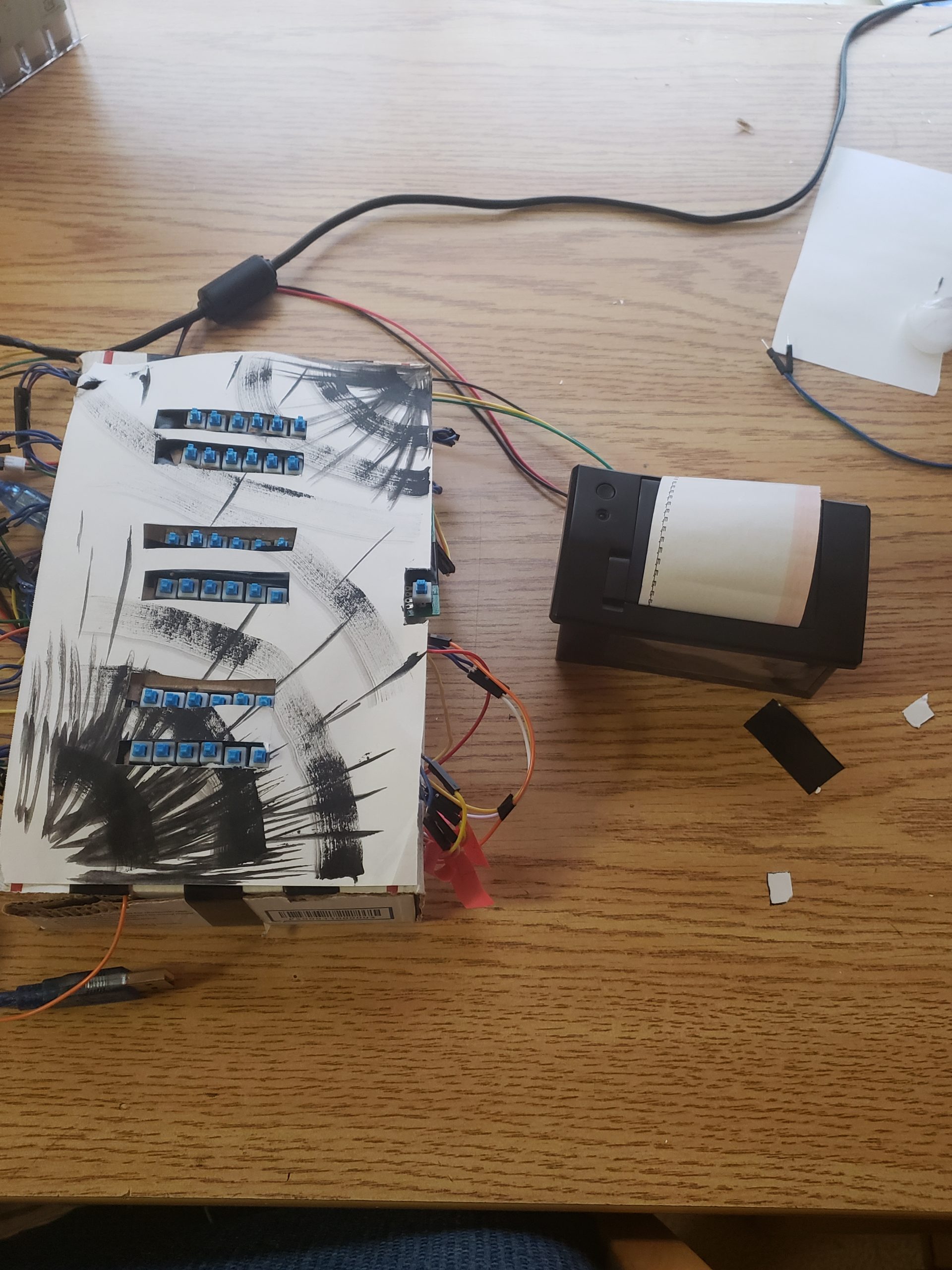
The finished project, for scale/ visual comprehension.
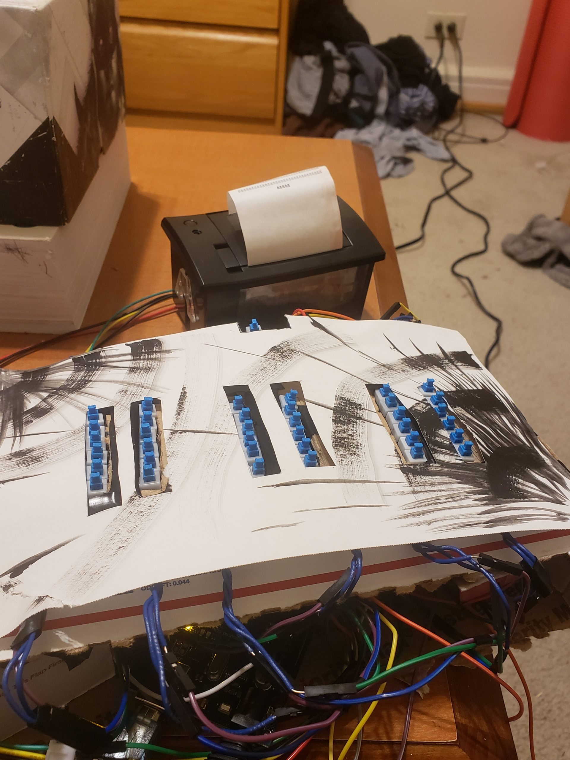
View of top panel the the – regrettably – bare keys.
Process Images
While developing this project, there were myriad decisions to make. Of these, a rather subtle choice that I made was to make the base key panels into modular things that can be wired into a system separately. All that they really are in the end are button arrays, and will certainly have utility in later projects. By setting the modules up to be reusable, it was possible later to restart designing without having to redo a lot of work. Another big point where things changed was when I realized that my original design did not work as-is. This was because I was down a large number of diodes. As a result, I needed to rethink the whole system, but this was arguably a good thing since it forced me to simplify my project significantly.
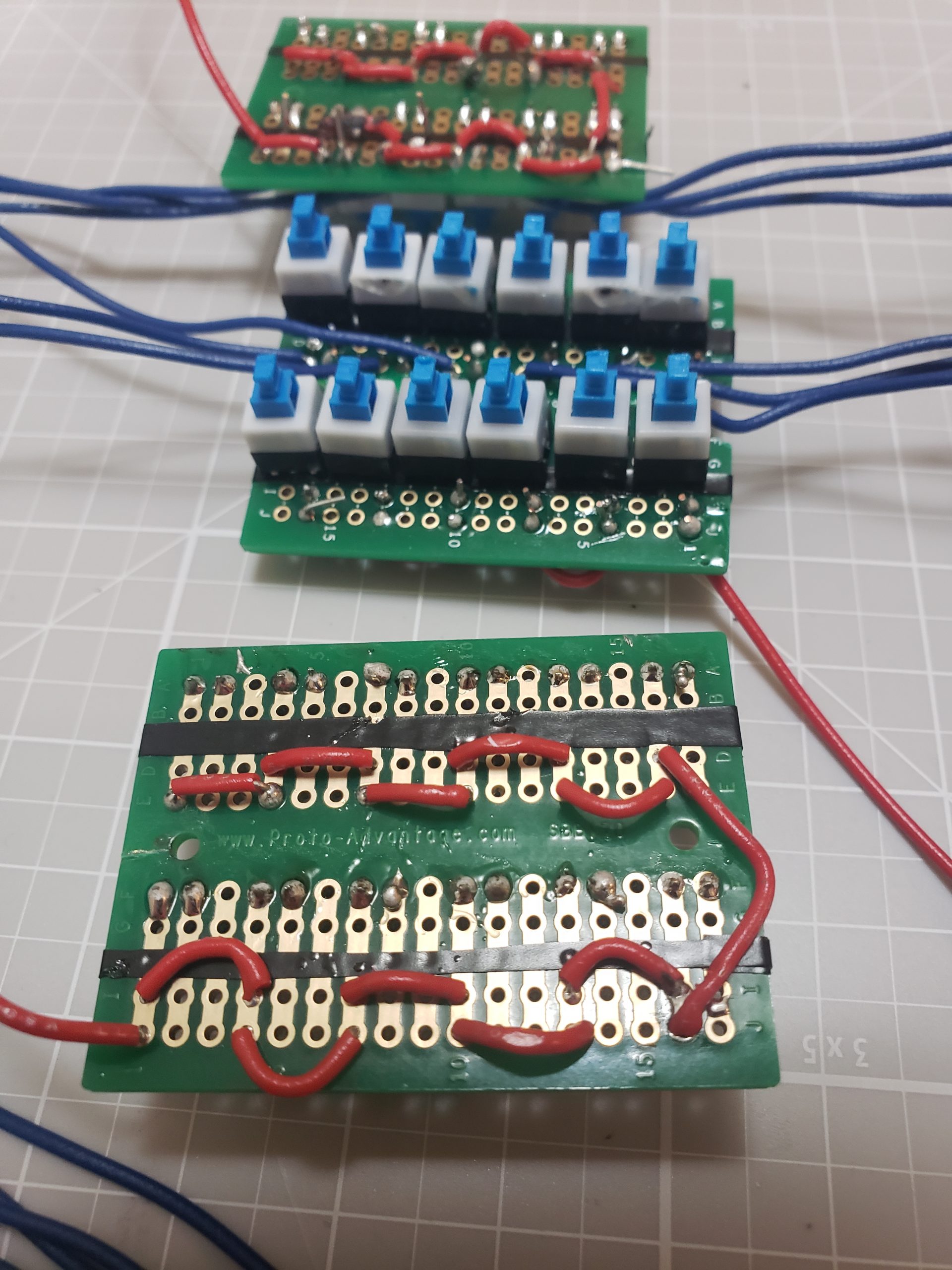
Each of these keyboard panels is designed to simply carry current out to the appropriate wire when a given button is pressed (provided that the red power lines are receiving power). These were crucial to make early, as the buttons used were not breadboard compatible. Each had to be soldered to
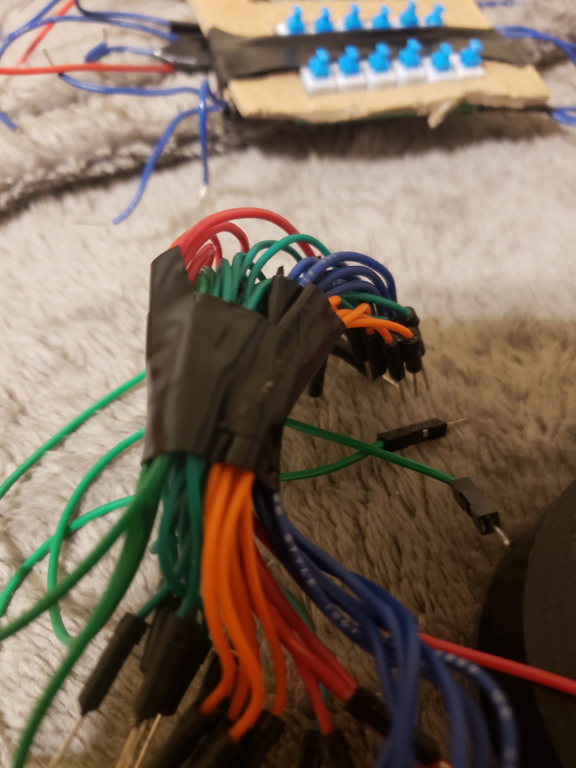
In this image, I’ve bundled all of the cables that go together so that management for wiring would be tractable (never mend tolerable). It might not be super clear, but the wires are individually bundled per color with tape, with all of the sub-bundles further bundled into one.
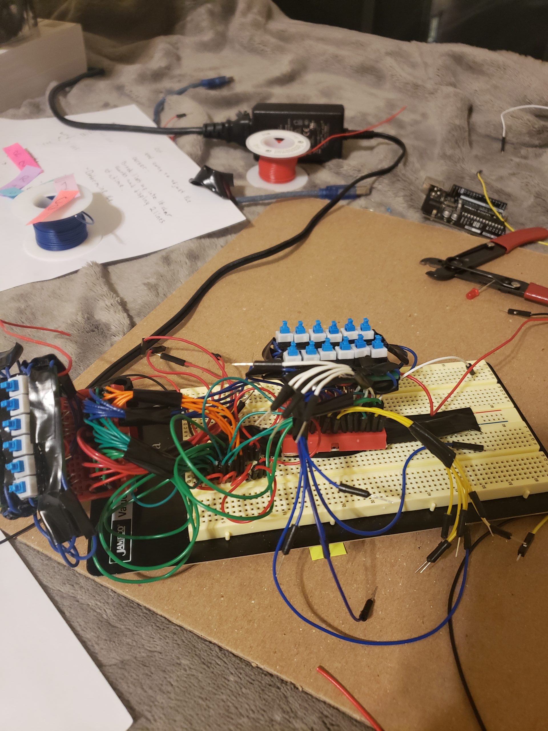
This image shows the beginning of wiring of the keyboard submodules to their corresponding selectors on the arduino. After doing some power flow testing, I realized that I had made a fatal flaw in my wiring – I was about 102 diodes short of making the board actually work.
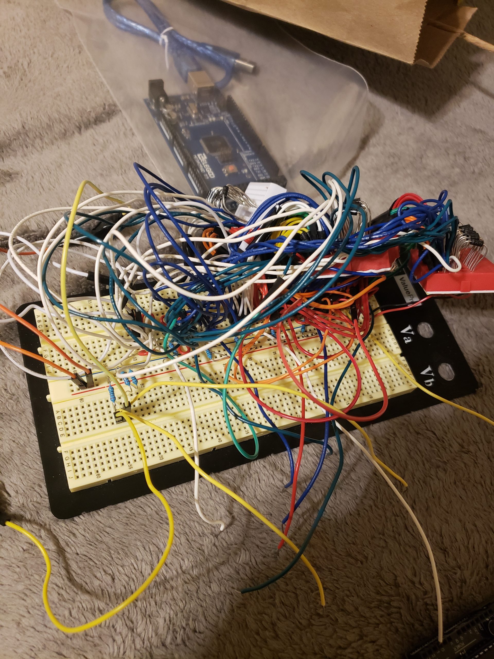
This image highlights the moment that I was prepared to take the original board apart and restart with the simpler design.
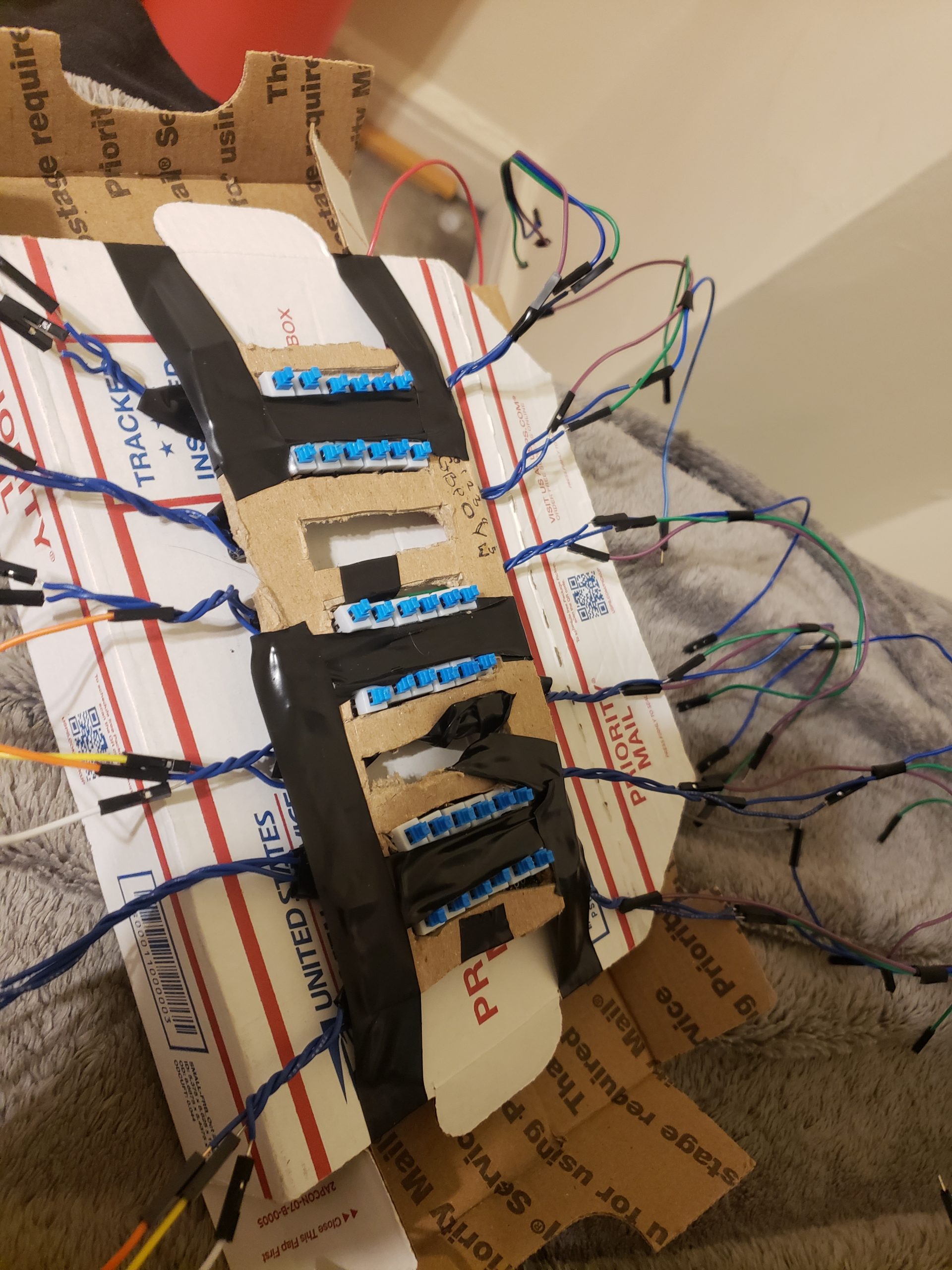
The moment where I bound the lighter-weight key interfaces to a cardboard case to make the shell for the keyboard.
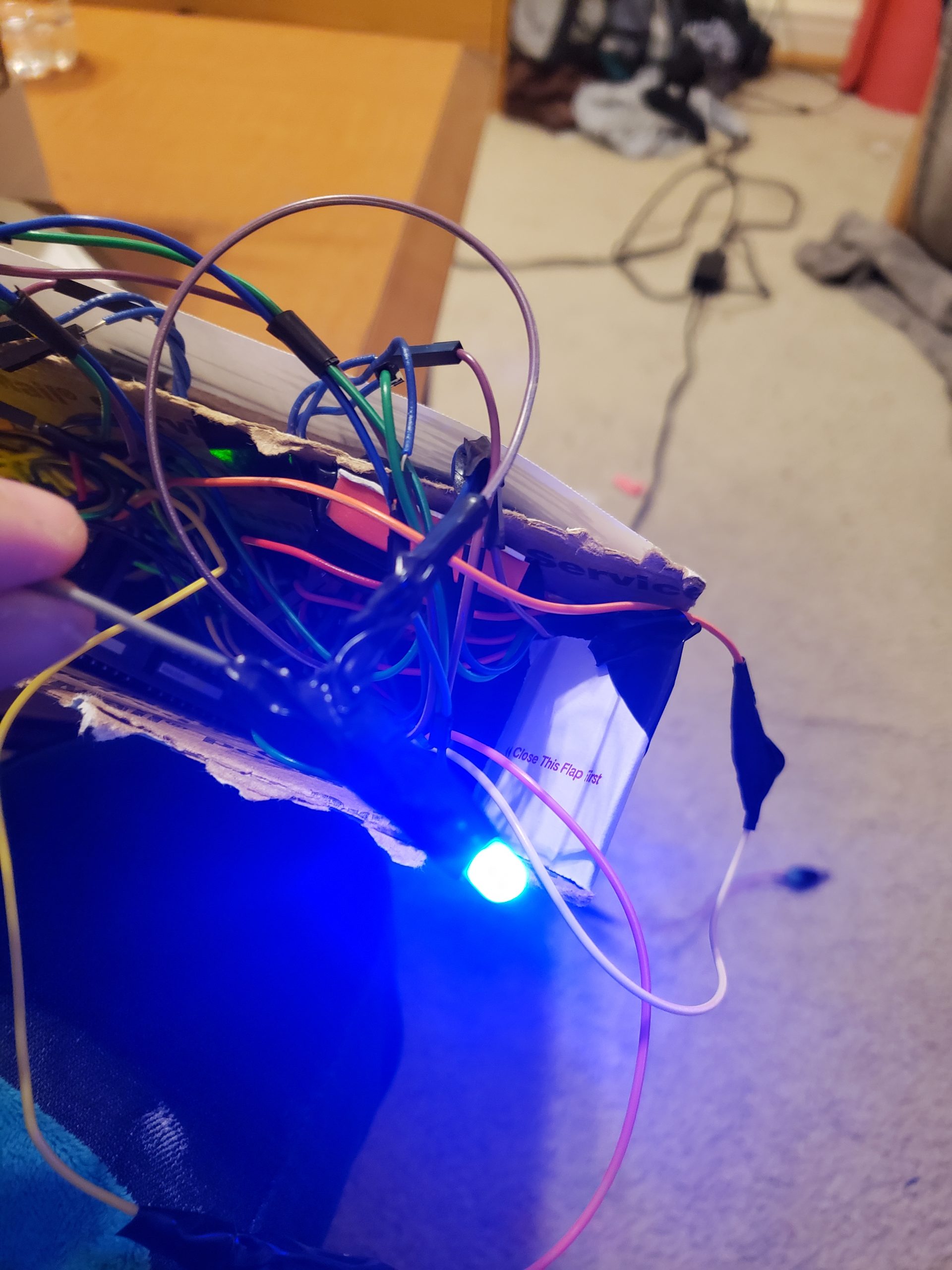
I like this image, mostly because of the deep blue aura around the LED has me thinking a bit more critically about how light reflects in air. This image shows the light indicating that the keyboard is being used turning on as a result of, well, the keyboard being activated.
Discussion
Looking over this project in hindsight, I feel that I learned a lot of lessons both big and small. Chief among them is that, no matter how long you think something will take to do in the world of complex projects with many small parts like this, your estimate WILL be wrong. I ended up sinking an entire weekend (October 24-26… 3 days I’ll never forget) into solely wiring the system and still couldn’t finish it due to unforeseen technical difficulties. That last bit stings the most, but I can’t say that it wasn’t my fault that this was the outcome – I should have thought more about the wiring before just jumping in and grinding it out. This is more evidence to me that, in order to really excel at a project with a seriously involved technical component, one should plan rigorously, and make sure to iron out all of the fine details before jumping in.
Considering the previous, I’m not totally satisfied with how the project itself turned out, but this is immaterial to me. More important than the product, I’ve gained a newfound appreciation for the process of developing custom electronics, and given that my system did (sort of) work in the end, I’m confident that in a future project or personal endeavor, given I plan effectively ahead of time, the outcome will be something much more exciting. There is still that looming notion of poor planning, and I think this is what allowed for such a languid final product.
All of the written peer critique that I received was rather positive. One states,
“I could tell you obviously put in a whole lot of effort! It’s a shame that you ran into so many wiring troubles, but cool idea overall.“
It’s certainly reassuring that the idea of the project wasn’t strangled out in the tangle of spaghetti-wiring!
Another reads,
“The idea was really cool! I can emphasize [sic] with having many ideas that I don’t know what to do with.”
Being such a scatterbrain myself, it feels good to know that the idea of trying to effectively reign the mind in is something that is appealing to others. As someone who’s lived their life with ADHD and OCD, often times my mind is inherently incapable of regulating its own direction and flow without manual intervention, but often this leads me to lose out on some really interesting streams of consciousness that will, well, never exist again. While I reckon that among the many preexisting methods for maintaining and logging thoughts what I’ve created here is not so novel, it would be nice to explore more novel methods to this end. There is something to be said about making something to solve your own problems as opposed to buying into a solution designed for an abstracted, generalized market.
Going forward, I think I’ll take more of my own time to create. I’ve always enjoyed visual arts and creative program, but the idea that I can essentially fold all of the power of a (tiny) computer into actual, physical projects is mind blowing. I feel a newfound fire in the engine that drives my work, and I want to ensure that it doesn’t burn out before I really carve out new ground. I now have a bunch of wired button arrays to use and a mountain of other electrical components that I feel more comfortable with beyond what I can learn from an ECE textbook. Alas, I can say all I like about what I could do, but this won’t matter until I actually do something.
While I’m not planning to iterate on this design (by the time you read it much of the project has likely been broken down for components), if I were to, there are two direction’s I’d take it. First, I’d dial back to the first circuit idea that I had – first, I’d strictly plan everything out and acquire every last required component to make the design, and do rigorous electrical testing throughout. This way, I wouldn’t be 80% of the way done only to learn that the rest of the non-cosmetic work is impossible to finish. The other, more likely direction I would take this would be to drop the arduino altogether and learn how to interface with a USB, as in a keyboard. This way, I could make a genuine physical keyboard out of the modules that I have. This would in all honesty probably be similar process-wise to the prior, but the end result, if constructed well enough, would be something that I’d be able to use in a variety of other situations.
Technical Portion
/* Arduino Receipt Printer and Keyboard Driver
 * by Evan Tipping
 *
 * The following code is used to drive an otherwise entirely mechanical keyboard,
 * store the input and print it out via a receipt printer.
 *
 * NOTE: This code requires and arduino Mega to work
 *
 * PINOUT:
 * A0 : Pin linked to print button
 * A1 : Pin linked to starting and stopping keyboard
 * A3 : Pin linked to space button
 *
 * 6 : TX Digital serial transmission to receipt printer
 * 5 : RX Digital serial reception from receipt printer
 *
 * start_pin to start_pin + 36 : Corresponds to a key in the keyboard
 *
 * Credit to https://github.com/pjreddie/darknet/blob/master/LICENSE.v1 for the idea of
 * writing a useless liscense :D
 *
 * Liscense Information:
 * lol what's the point of liscensing code that's not being used in security-critical
 * applications? our modern legal system already failed and mostly serves to protect
 * those in a position of power and even if this code had a different liscense it's
 * not like I could afford a lawyer to defend myself. basically go nuts!
 */

#include <EEPROM.h>
#include "Adafruit_Thermal.h"
#include "SoftwareSerial.h"

const int MEM_LIM = 4096; // Length of EEPROM, board dependant
int mem_start;
int start_pin = 18;

bool typing = false;

const int PIN_PRINT = A0;
const int PIN_WRITE = A1;
const int PIN_SPACE = A3;
int TX_PIN = 6; // Arduino transmit  YELLOW WIRE  labeled RX on printer
int RX_PIN = 5; // Arduino receive   GREEN WIRE   labeled TX on printer

// Needed to operate keyboard
const char key_array[36] = {'0', '1', '2', '3', '4', '5',
                            '6', '7', '8', '9', 'a', 'b',
                            'c', 'd', 'e', 'f', 'g', 'h',
                            'i', 'j', 'k', 'l', 'm', 'n',
                            'o', 'p', 'q', 'r', 's', 't',
                            'u', 'v', 'w', 'x', 'y', 'z'};


SoftwareSerial mySerial(RX_PIN, TX_PIN); // Declare SoftwareSerial obj first
Adafruit_Thermal printer(&mySerial);     // Pass addr to printer constructor

// Establish the top 36 inputs in the MEGA to be keys
void set_key_pins() {
  for (int i = start_pin; i < start_pin + 36; i++) {
    pinMode(i, INPUT_PULLUP); // Use for button
  }
}

char get_char_pressed() {
  for (int i = start_pin; i < start_pin + 36 - 10; i++) {
    if (!digitalRead(i)) { // Extra check accounting for.. hardware failure..
      return key_array[i]; // Otherwise use regular key indexing
    }
  }
  if (false){//digitalRead(PIN_SPACE)) {
    return ' '; // If the space key is pressed, return a space character
  }
  return '\0';
}

void print_msg(char* msg_buf) {
  printer.boldOn();
  printer.println(msg_buf);
  printer.boldOff();
}

void print_mem() {
  char str_msg[MEM_LIM];
  for (int i = 0; i < mem_start; i++) {
    int j = 0; // Index in message
    char chr_msg;
    while ((chr_msg = EEPROM.read(i)) != '\0') { // While not at end of string
      str_msg[j] = chr_msg;
      i++;
      j++;
    }
    str_msg[j+1] = '\0';
    Serial.println(str_msg);
    print_msg(str_msg);
  }
}

int find_mem_start() {
  int eeprom_end = 0;
  while (EEPROM.read(eeprom_end) != '\0' && eeprom_end < MEM_LIM) {
    Serial.println(eeprom_end);
    eeprom_end++;
  }
  if (eeprom_end != 0) {
    eeprom_end++; // Skip over the null terminator if we aren't at start of memory
  }
  return eeprom_end;
}


bool mem_full() {
  return mem_start >= MEM_LIM - 1; // This is to ensure that there is a '\0' at end of eeprom
}

void write_to_mem(char key_pressed) {
    EEPROM.write(mem_start, key_pressed);
    mem_start++;
    EEPROM.write(mem_start, '\0');
}


void clear_eeprom() {
  for (int i = 0; i < mem_start; i++) {
    EEPROM.write(i, 0);
  }
}

/*
 * SETUP SYSTEM
 */
void setup() {
  set_key_pins();
  mem_start = find_mem_start();

  pinMode(PIN_PRINT, INPUT_PULLUP);
  pinMode(PIN_WRITE, INPUT_PULLUP);
  pinMode(PIN_SPACE, INPUT_PULLUP);

  // Find end of EEPROM string
  Serial.begin(9600);

  mySerial.begin(19200);  // Initialize SoftwareSerial
  printer.begin();        // Init printer (same regardless of serial type)
  printer.justify('C');
}

/*
 * LOOP TO DRIVE THE BOARD
 */
void loop() {
  digitalWrite(A2, LOW);
  if (typing) {
    int old_start = mem_start;
    char key_pressed = get_char_pressed();
    if (key_pressed != '\0') {
      char dbg_buf[2];
      dbg_buf[1] = '\0';
      dbg_buf[0] = key_pressed;
      digitalWrite(A2, HIGH);
      write_to_mem(key_pressed);
    }
    if (!digitalRead(PIN_WRITE) || mem_full()) {
      typing = false; // Cancel typing early as there's no room left in memory or the user pressed the keyboard controller
      if (!mem_full() && !(old_start == mem_start)) mem_start++; // Skip null terminator from prior string
    }
  } else {
    if (!digitalRead(PIN_WRITE)) {
      typing = true;
    }
    else if (!digitalRead(PIN_PRINT)) {
        digitalWrite(A2, HIGH);
        print_mem();
        clear_eeprom();
      }
    }
  delay(300);
}
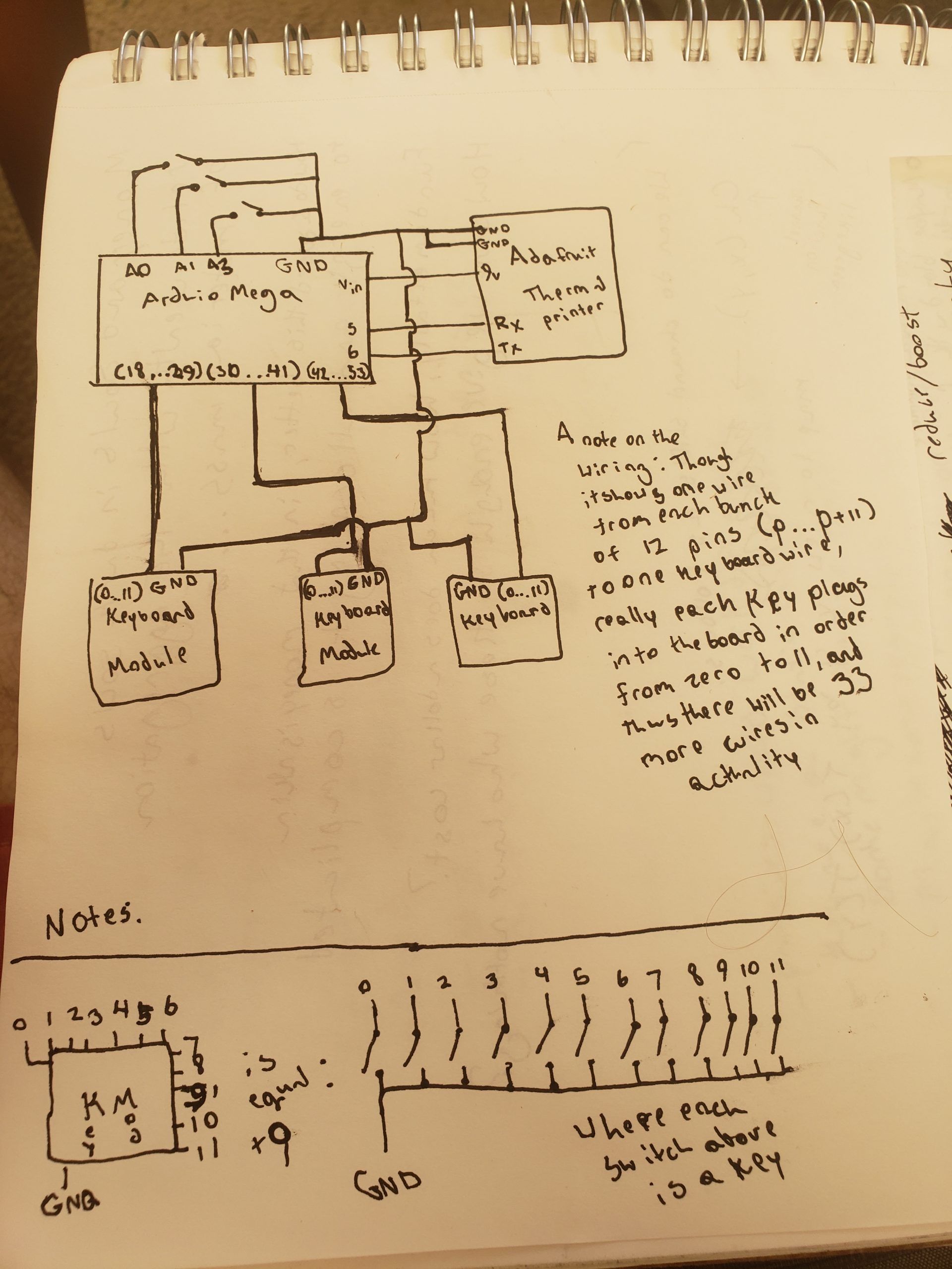
Electrical schematic for this project.