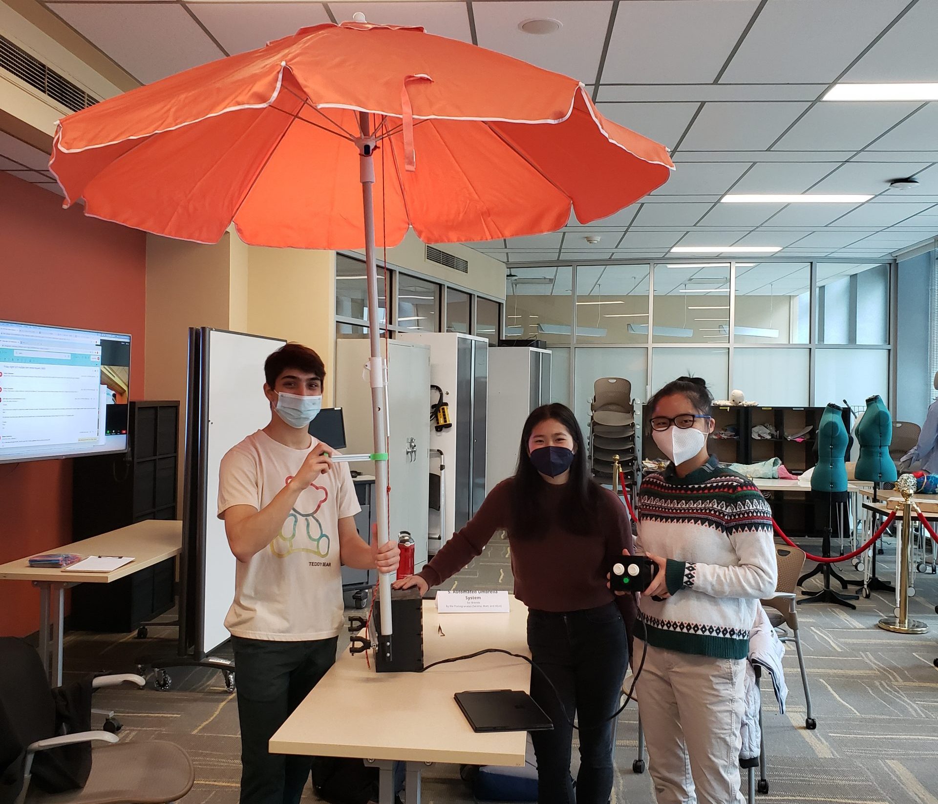
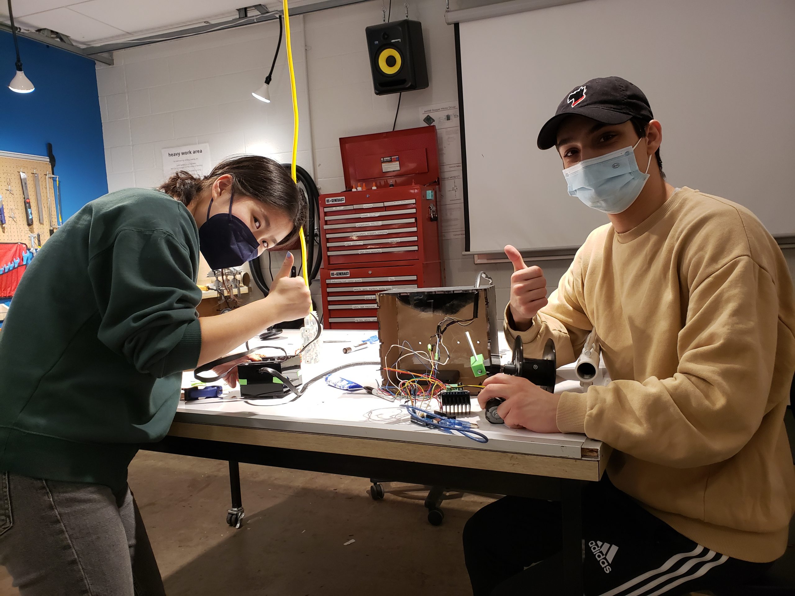
Matthew Wagner, Serena Ying, Yuqi (Alice) Zhou for Brenda
1. Introduction
For our final project, we were tasked to work with a client to develop a personal assistive device which would help improve an aspect of their lives. Our client, Brenda, uses a power chair and spends the majority of her time with it due to limited mobility. One problem she was very enthusiastic about solving was using an umbrella that would cover the electronics on her power chair if it was raining, and which could also be used as a sunshade when she participates in protests in the summer. So, for our project, we decided to realize the idea that Brenda proposed– an automated umbrella opener and closer which could be mounted on the back of her chair and activated easily without having to hold the actual umbrella. For more details and interview documentation with Brenda, please see here:
Interview Documentation Team Pomegranates
2. What We Built
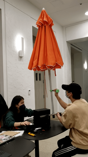
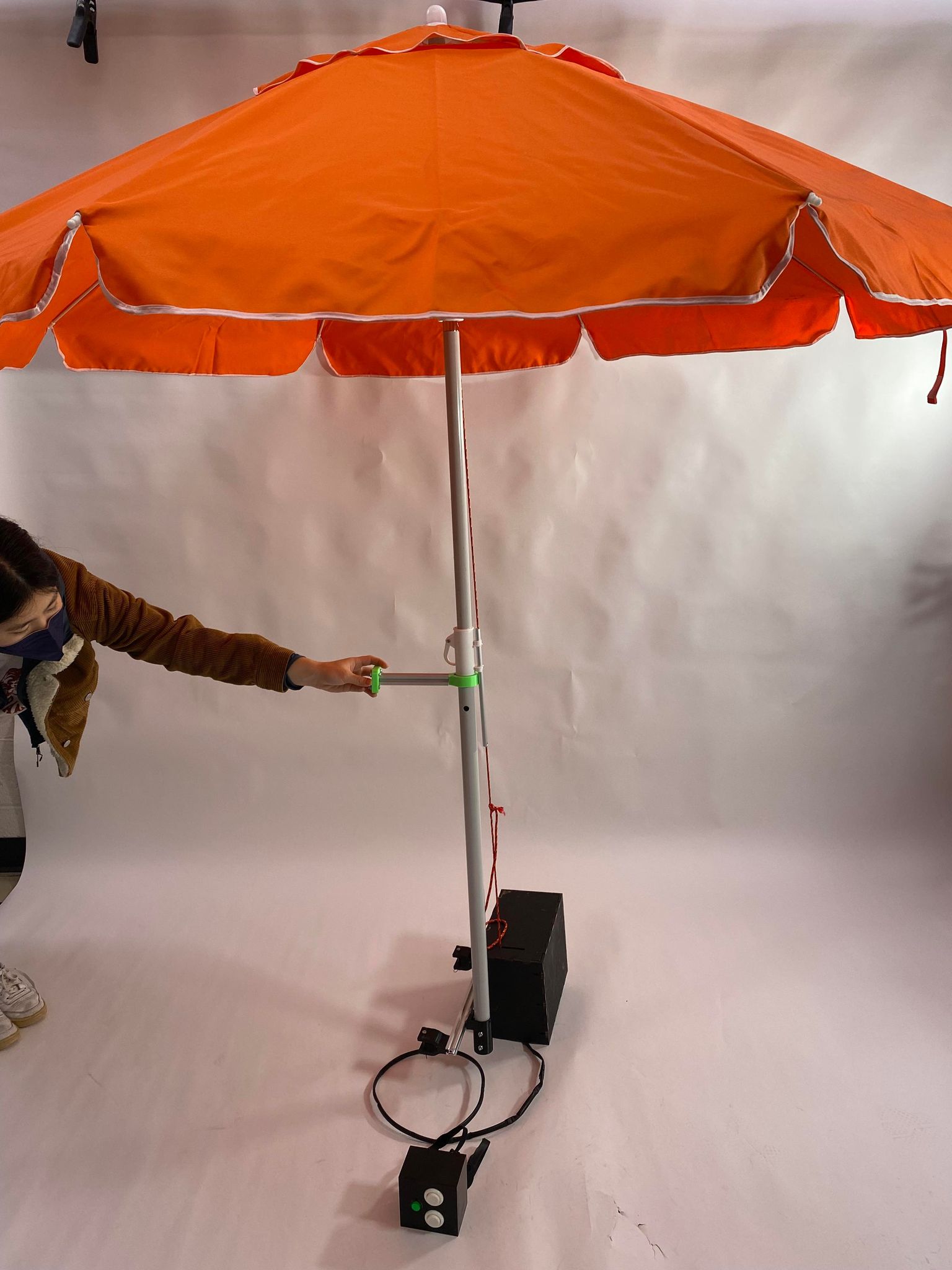
Our project works very simply. The umbrella and the control boxes are to be mounted to a power chair, utilizing the existing interface of the back of the chair. The device has three buttons the user operates to control the umbrella. The power button allows the other buttons to be activated, so the umbrella isn’t accidentally raised or lowered when not desired. The device plays a little jingle to alert the user that the device is on. From there the user uses the other two buttons to raise and lower the umbrella respectively. The buttons activate a motor which pulls a string attached to the top of the umbrella, to pull it to the open position.
Since Brenda wasn’t able to make it to our final critique, we weren’t able to mount the device on her wheelchair. However, we look forward to connecting in the future.
Final working video – button presses engage motor either CW or CCW to pull rope through pulleys mounted in the base box and at the umbrella apex and tension or release the umbrella
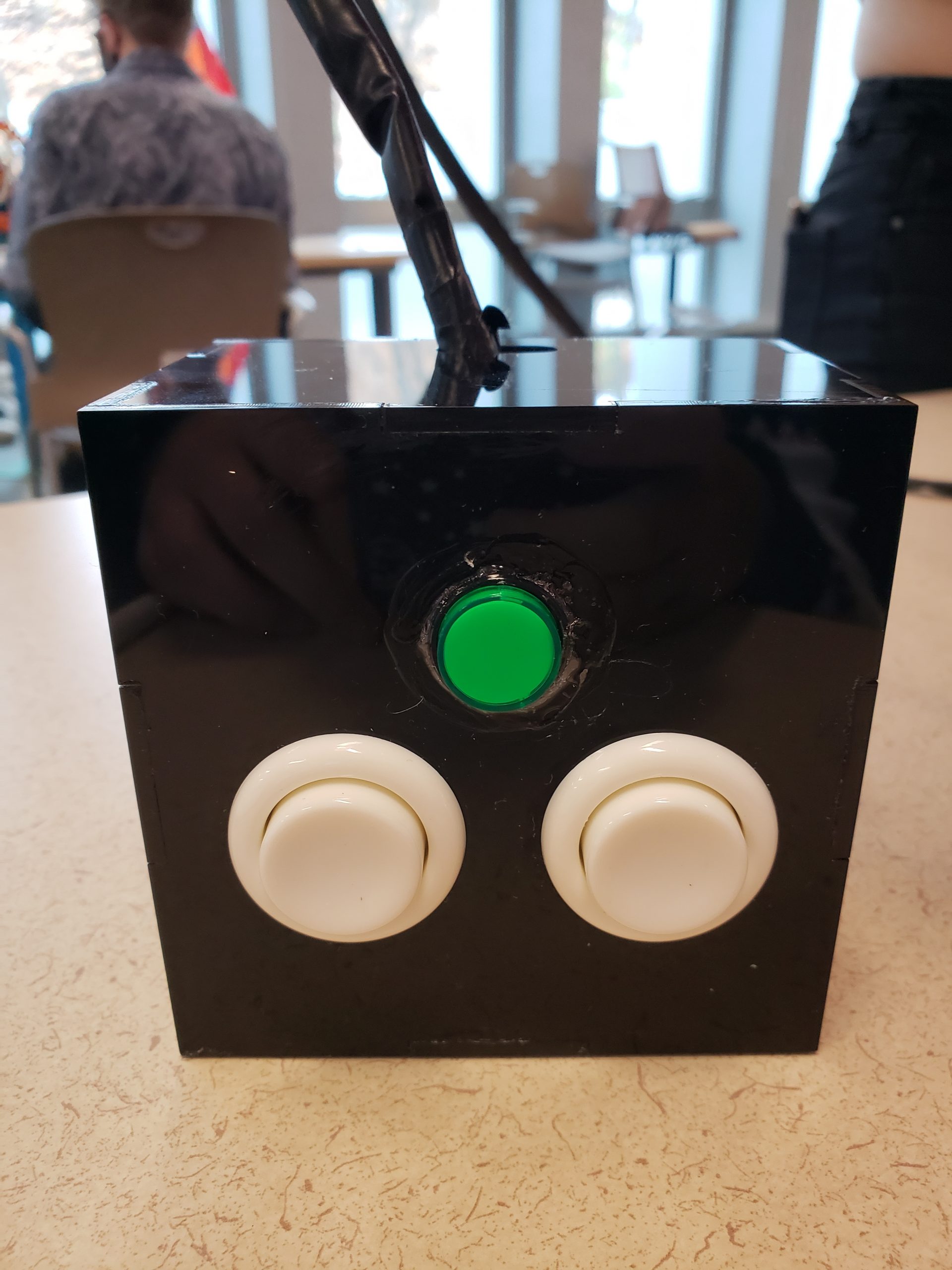
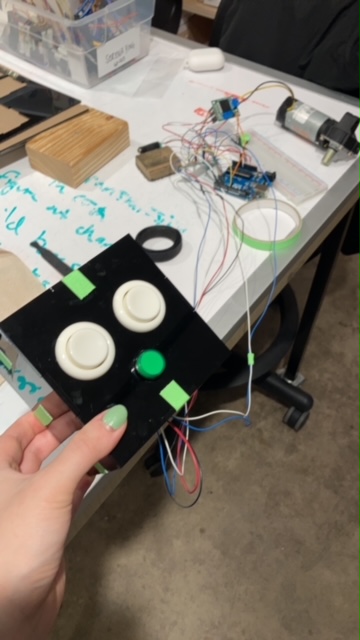
The Control Box houses the buttons that Brenda uses to power on/off (green) the device as well as raise and lower the umbrella. The box is mounted such that the two white buttons are aligned vertically, where “raise” is on top of “lower”.
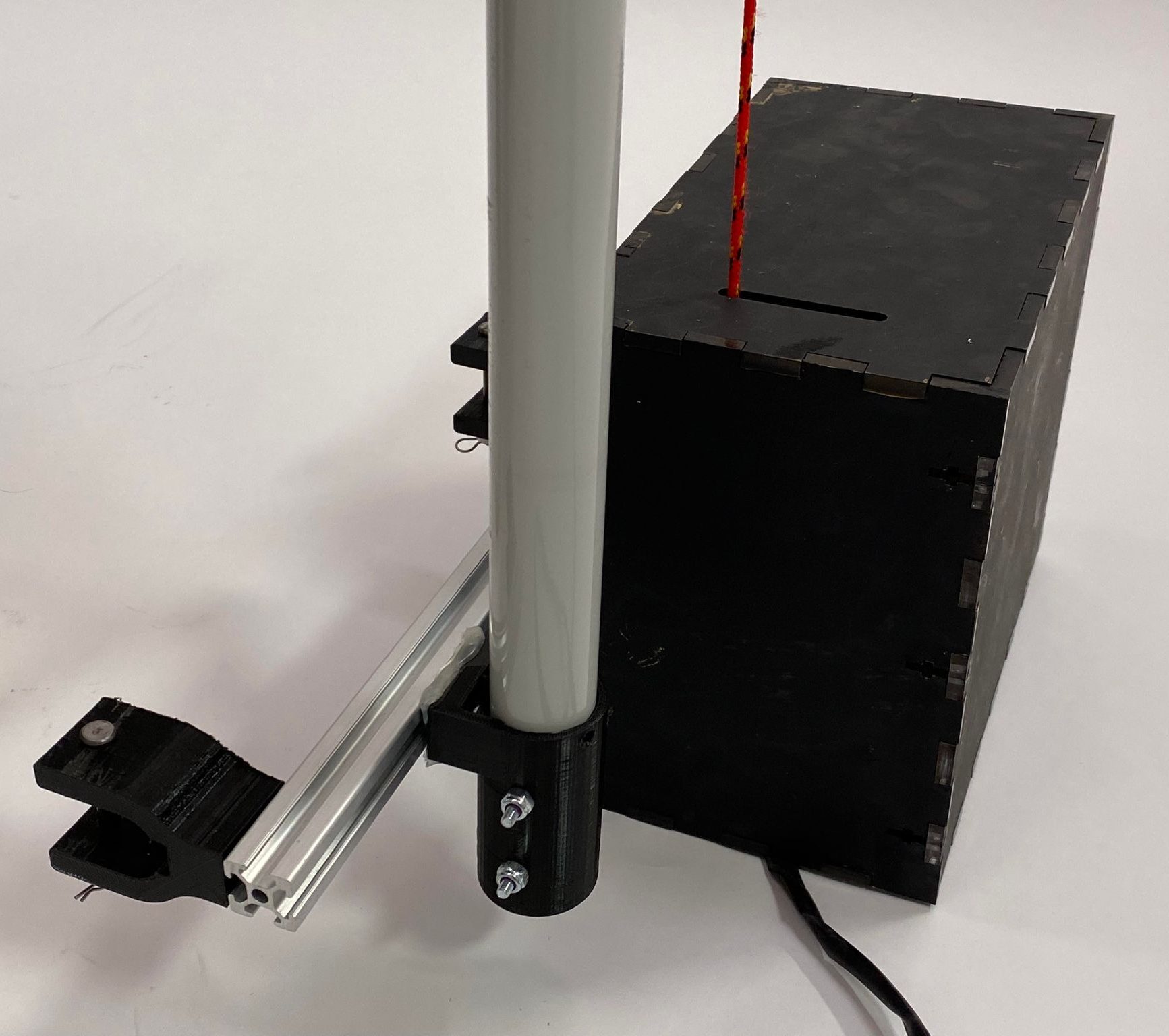
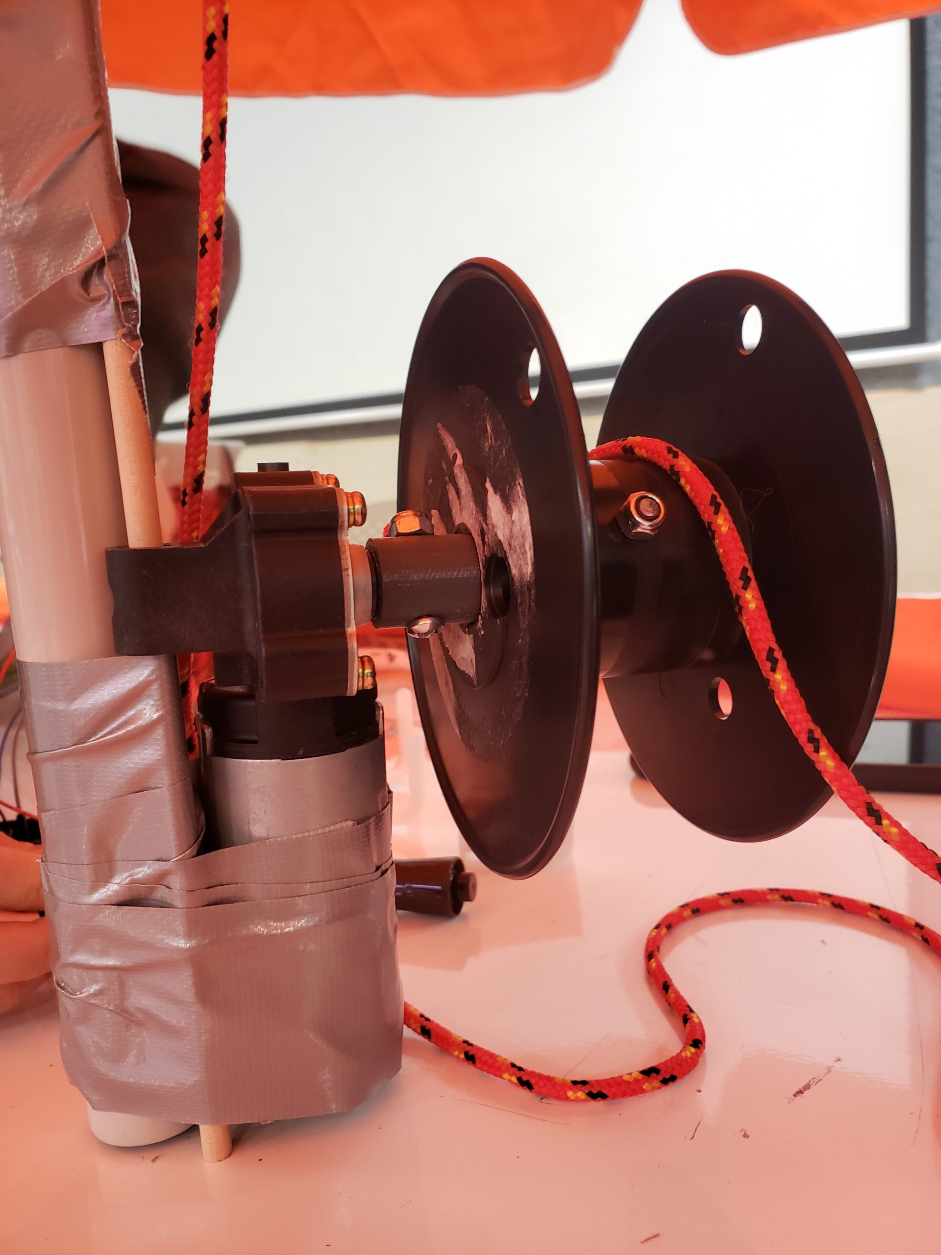
The box hosting the wiring, motor and pulley system.
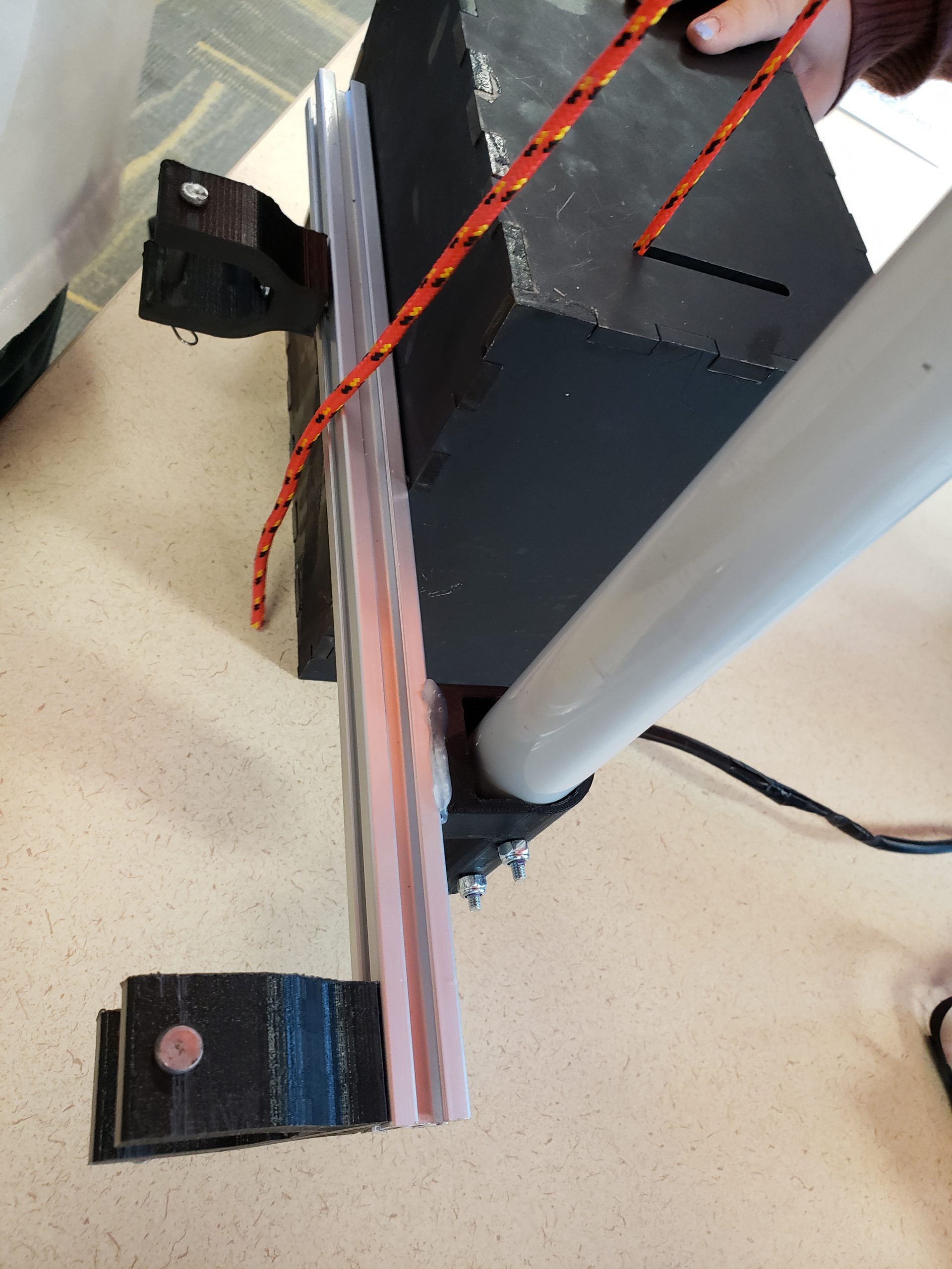
The box as well as the umbrella itself are mounted to an aluminum extrusion beam.
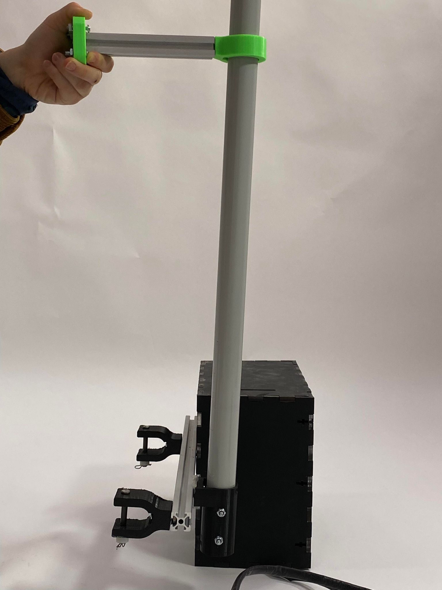
The aluminum extrusion beam attaches to Brenda’s chair using the black clips that pin to cylindrical components of the chair. The pole of the umbrella is also connected similarly to where Brenda’s headrest is, to prevent the umbrella from wanting to rotate.
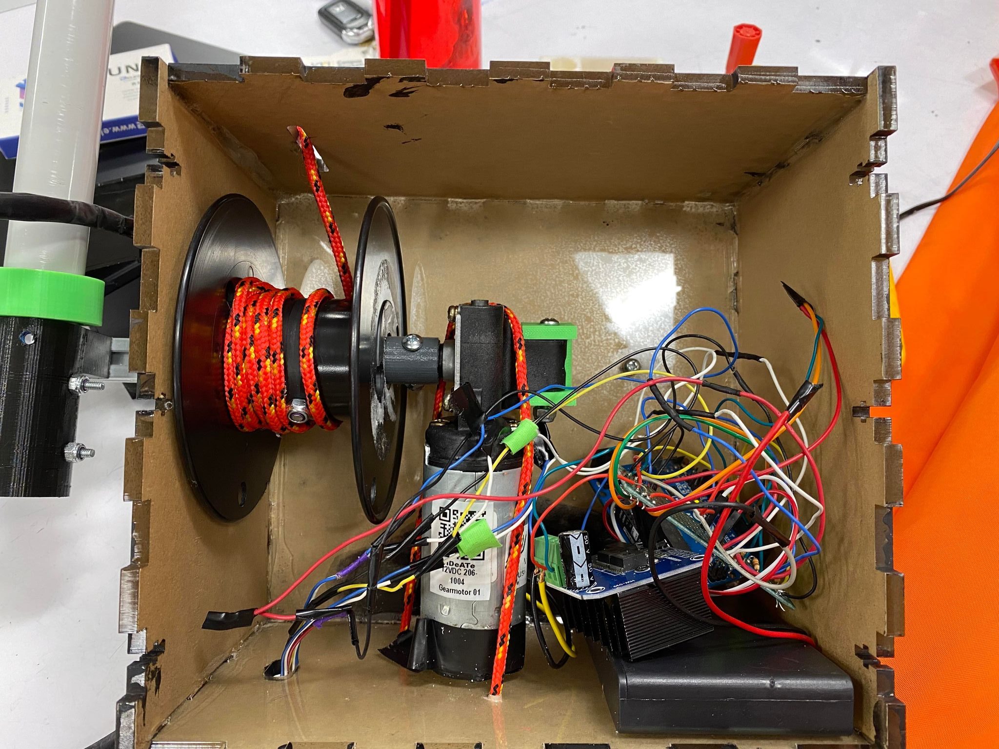
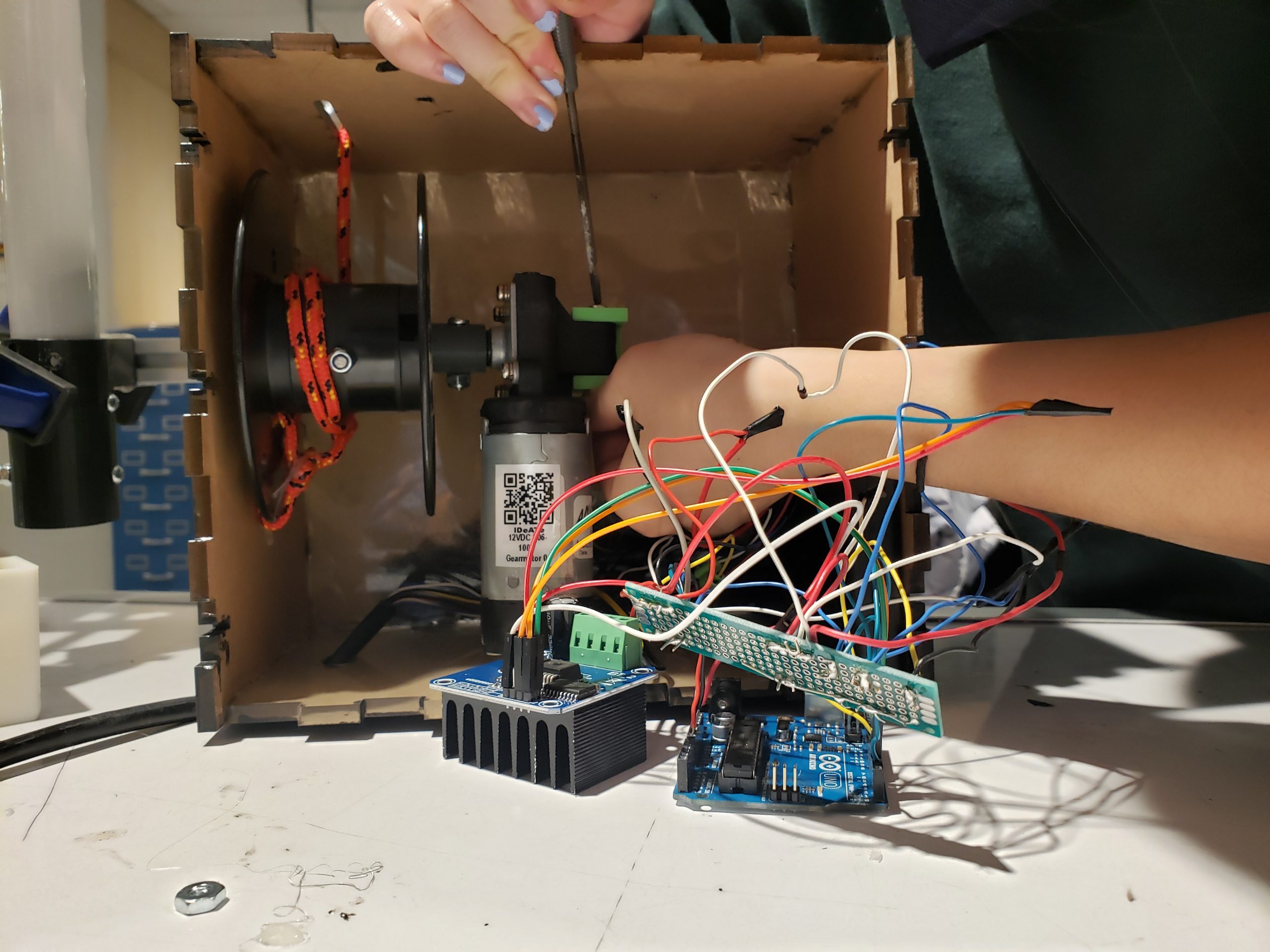
An inside look at the box shows the orientation of the motor amidst the wires and battery pack used to power the device. The motor spins the pully to wind and release the string used to raise and lower the umbrella. The worm gear inside the motor, prevents rotation of the axel when the motor is shut off or when the umbrella is raised so that it stays raised during use.
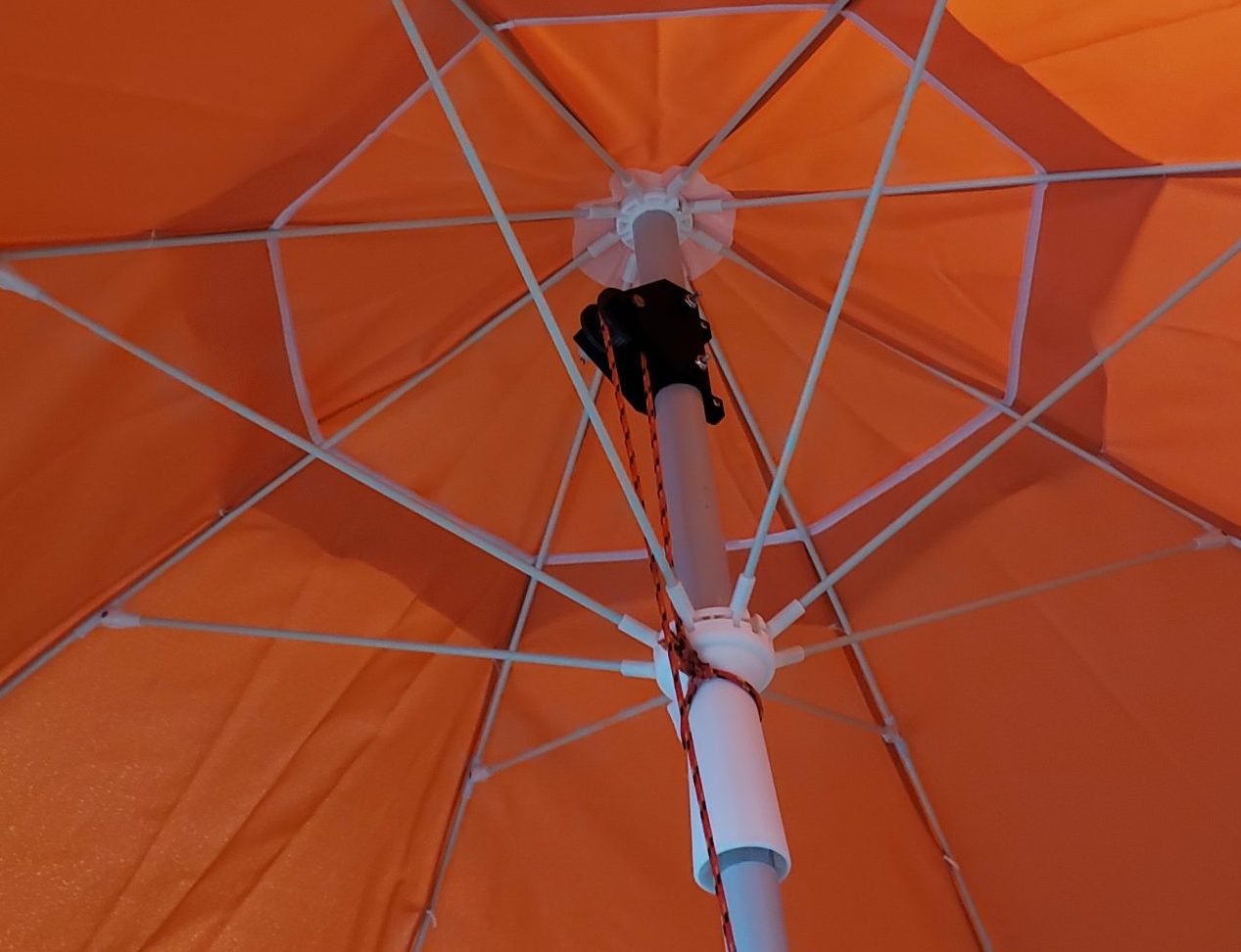
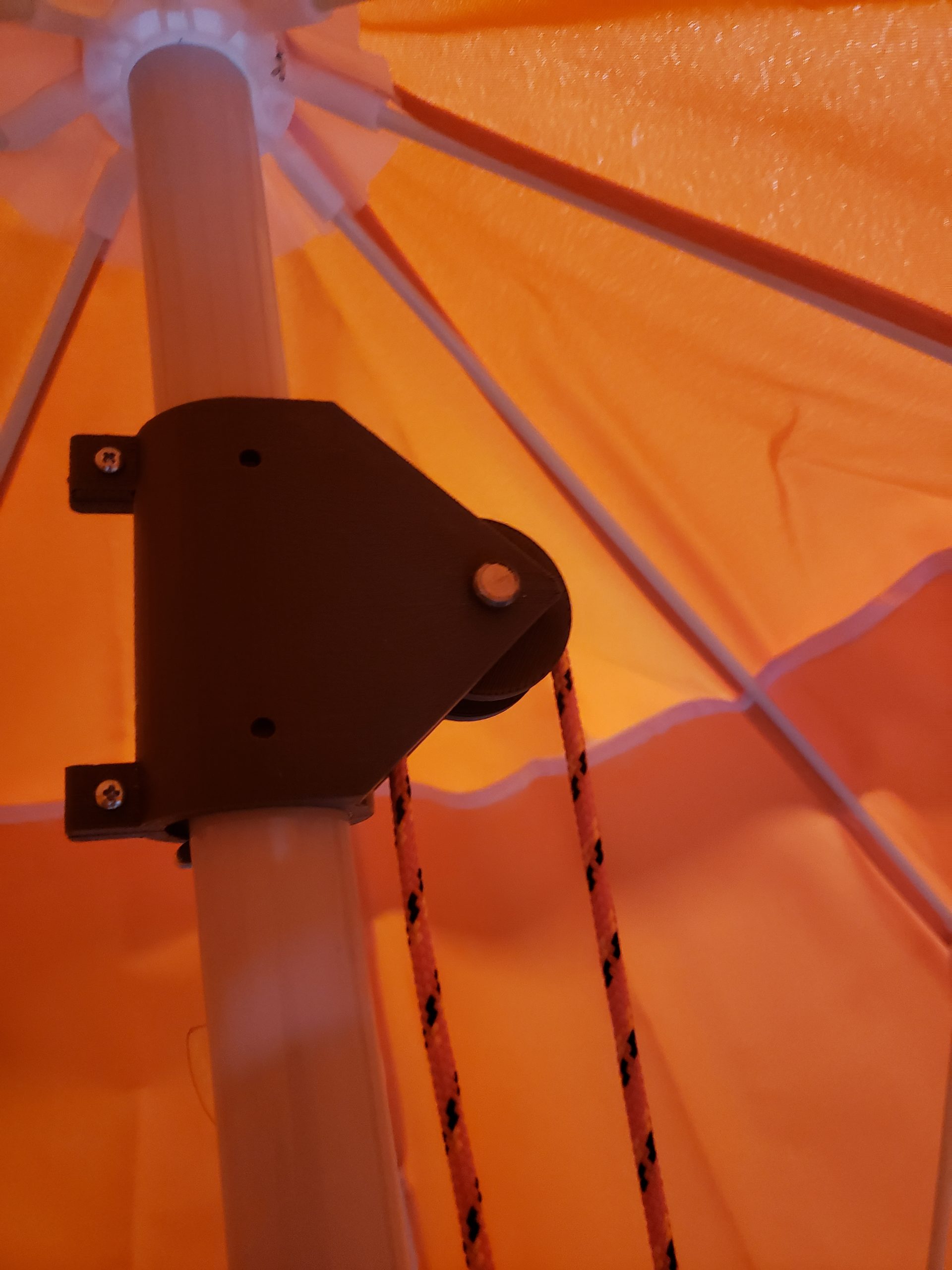
The string goes up the pole of the umbrella and around another pully fixed at a bearing at the top of the umbrella. This bearing is bolted into the umbrella pole allowing the string to pull up the “runner” which slides up the pole to open the umbrella. Typically, the runner is moved manually, but our device automates this procedure.
Umbrella at a open position
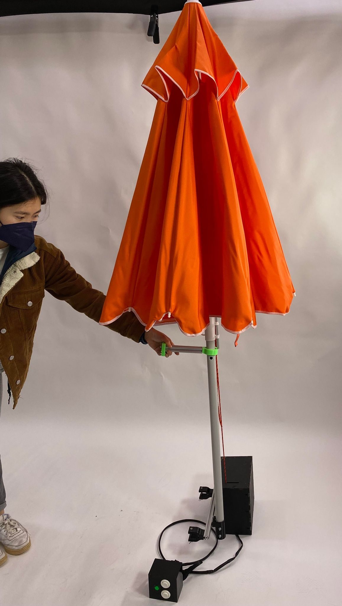
Umbrella at a close position
Brenda spends most of her waking hours sitting in her wheelchair, so accessibility is super important. On a given rainy or very sunny day, Brenda would decide to use our assistive device to protect her from the elements. With some help attaching the mount to the back of her power chair, Brenda is ready to be outside and go about her journey without any additional assistance. With the press of a button that is easily in reach on her left arm rest, Brenda powers the device, allowing her to control raising and lowering the umbrella by pressing and holding the adjacent buttons. The umbrella is able raise and lower while not obstructing Brenda’s vision in front of her and protects the entirety of the power chair due to the large diameter when raised.
On a particular rainy day, Brenda doesn’t worry about driving her chair through the rain because the umbrella will protect the controls and electrical components of the chair that are susceptible to water damage. The umbrella will protect her from the rain, and she is able to raise and lower the umbrella freely to accommodate her busy work schedule.
In the summer, Brenda chooses to attend a protest but is worried her chair’s stature will cause her to get lost in the crowds. To both protect her from the sun and help the people she is with to identify her in a crowd, Brenda uses our device to stay safe and be independent while fighting for what she believes in.
3. Prototypes and Process
This prototype was designed to help answer one question: does the motor we decided to use to pull the umbrella open have enough torque to lift the runner of the umbrella due to the umbrella’s size and weight.
For our prototype, we only utilized the top half the umbrella pole and attached the motor, pulley assembly to the pole using duct-tape. Using a borrowed motor driver and a lever switch, we were able to control up, then down of the umbrella using a single press for each. At this stage the switch activated the motor to rotate for a fixed amount of time. We had to hold the umbrella upright as no mount was created at this point. Additionally, we designed and 3-D printed a bearing for the top of the umbrella which held a pully, allowing the string to raise the umbrella. The motor wounds the string in tension to pull up, and releases that tension, relying on gravity to bring the umbrella back to the lowered position.
We grounded the motor to the base of the umbrella pole using duct-tape. This ensured consistency in the raising and lowering as the motor was only set to rotate for a specific amount of time.
The first iteration of the bearing we made was too big for the width of the pole. This happened because we had to send the part to the 3D printers before the umbrella was delivered. We were able to use a piece meant to lock the runner in place to rest the bearing on during the prototyping phase. The same design was updated with a smaller diameter for the final product.
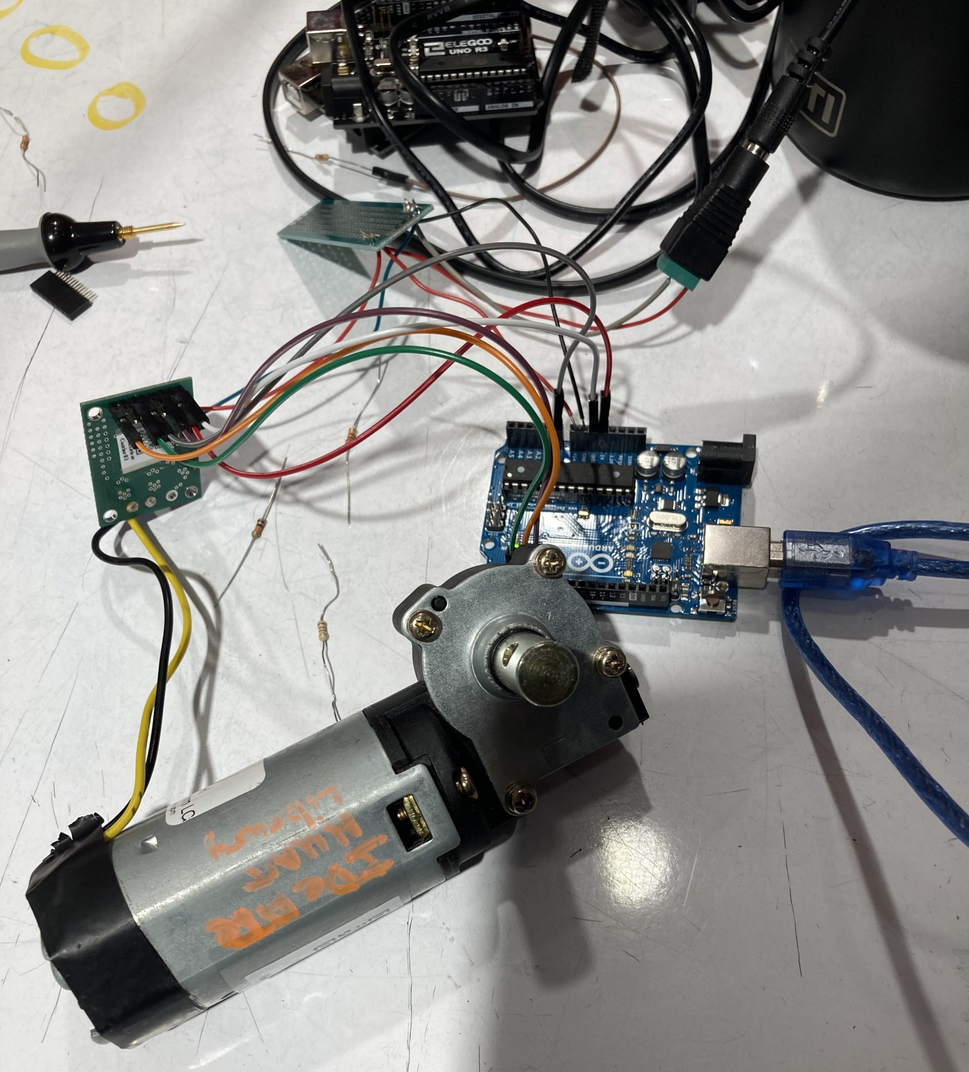
Figuring out the wirings for the motor
Prototype of motor with bottom pulley attached responding to up and down button presses
Findings from the Prototyping Process
The answer is: the motor we decided to use does have enough torque to lift the runner of the umbrella and pull the umbrella open despite the size and weight of the umbrella.
Feedback from the Critiques
One feedback we received from the critique was on the power of the system. For the prototype, to supply power, we had to plug in a 12v power supply. That is not ideal because Brenda would need to find power supplies. Thus, we decided to change it so that the whole system is powered by a battery pack; changing batteries once in a while is comparably easier.
Another feedback we received was concerning the accidental activation of the system. Based on the feedback, we added an on/off button to act as the safety switch. The up/down control buttons would not work unless this on/off button is pressed; this adds another layer of protection to accidental activation.
One feedback we didn’t quite address in our final design was designing for different umbrellas. Brenda mentioned umbrellas are consumables, so she would like the system to be usable by other umbrellas as well. We tried to address this feedback, however, ended up focusing on making the system work for the specific umbrella we had. If we had more time, we would love to make it work with other umbrellas as well.
Surprises
One surprise knowledge we learned during the prototype process was that humans can act as resistors. We were wiring the motor and at one point, the motor only ran when a person was holding the wires. We tried adding in a resistor, and it sort of worked. So, we learned humans can have resistance of as high as 100,000 ohms. However, in the end, it turned out that we didn’t have a ground for the wiring which was the real problem. So, now we know humans can act as both resistors and ground.
Process
A lot of planning, drafting, redrafting, and revisions went into designing this project. Here is a (mostly) chronological record of our work sessions throughout the weeks.
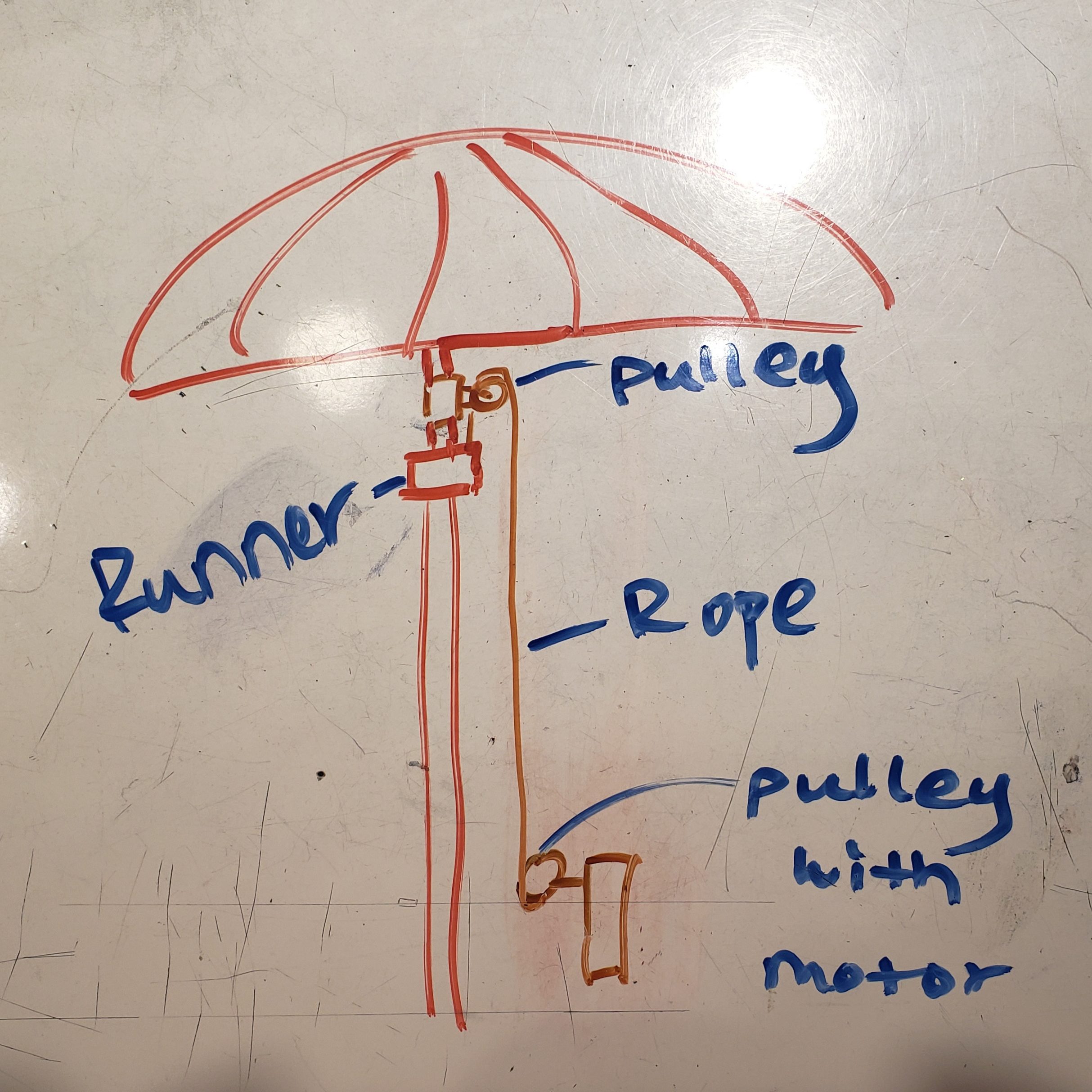
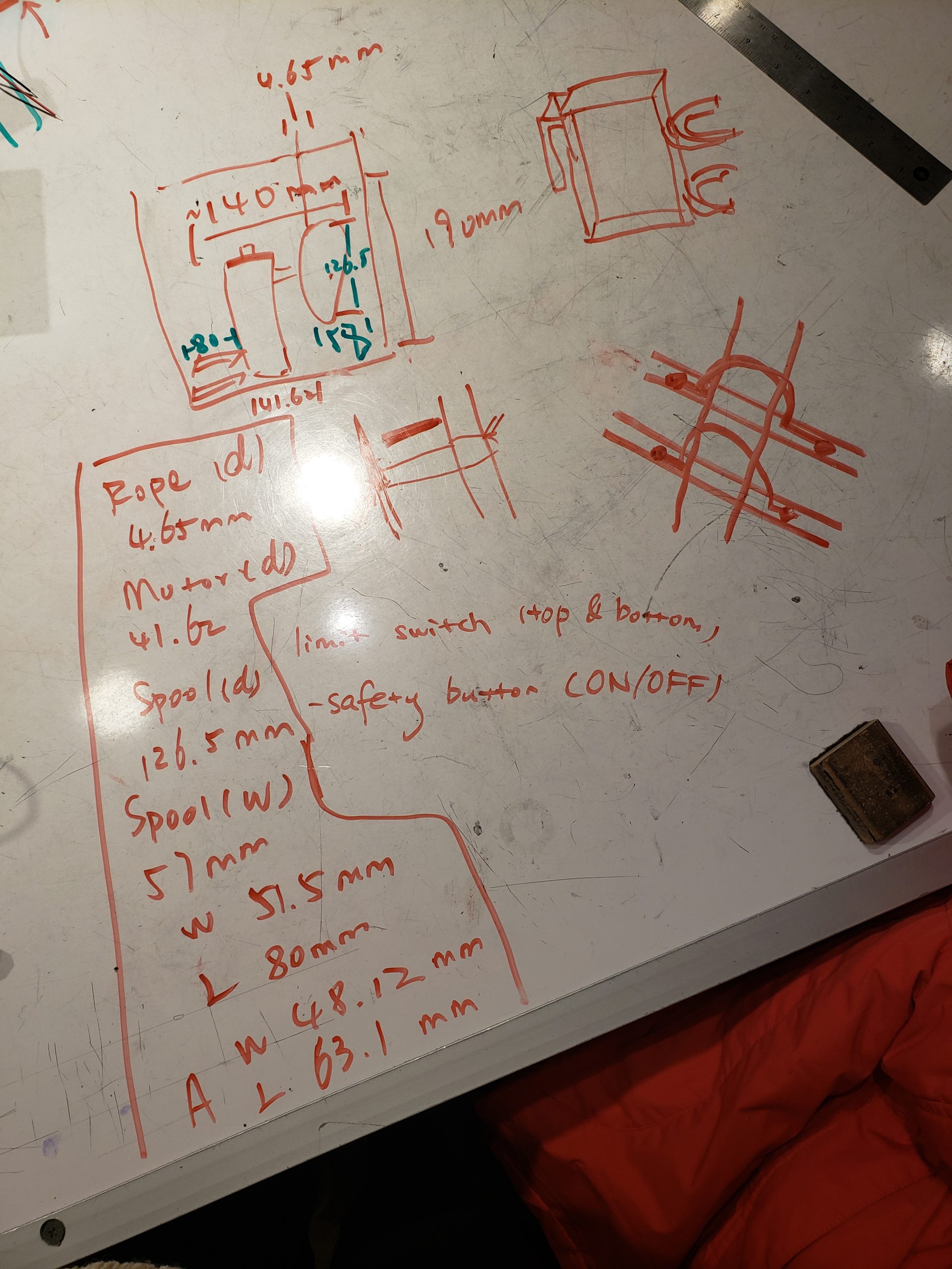
Initial schematic drawn for clarity after scrapping the gear track idea and confirming that the beach umbrella was gravity tensioned
After we received the umbrella, work sessions got a lot more crowded but way more tangible. We made a ton of design choices and swapped out parts from IDeATe Lending out for ordered components– sometimes requiring rewiring and redesigning.
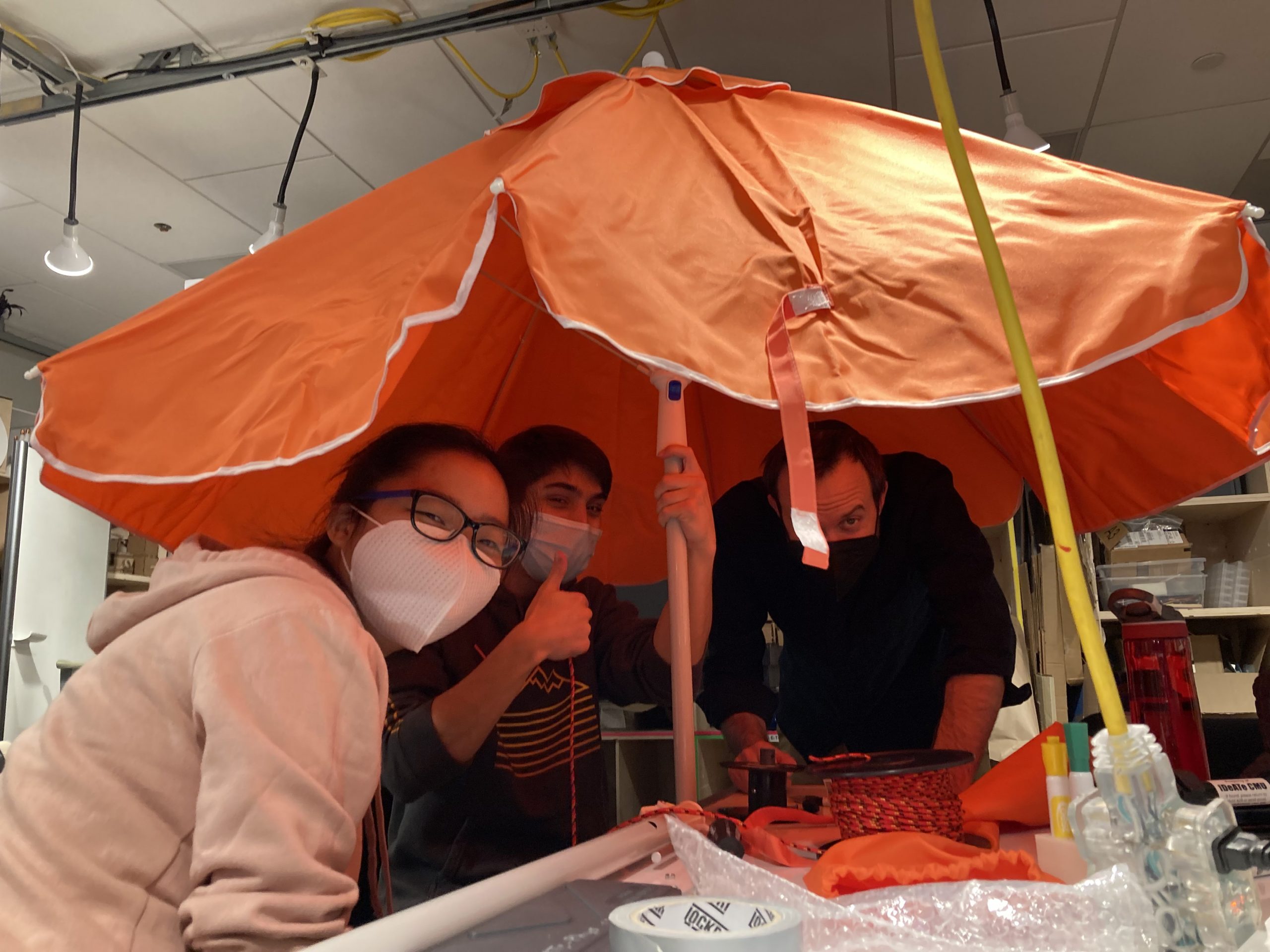
Umbrella is usable in midst of figuring out how to attach runner to pulleys!
Fitting the lever switches with arcade buttons for ease of use
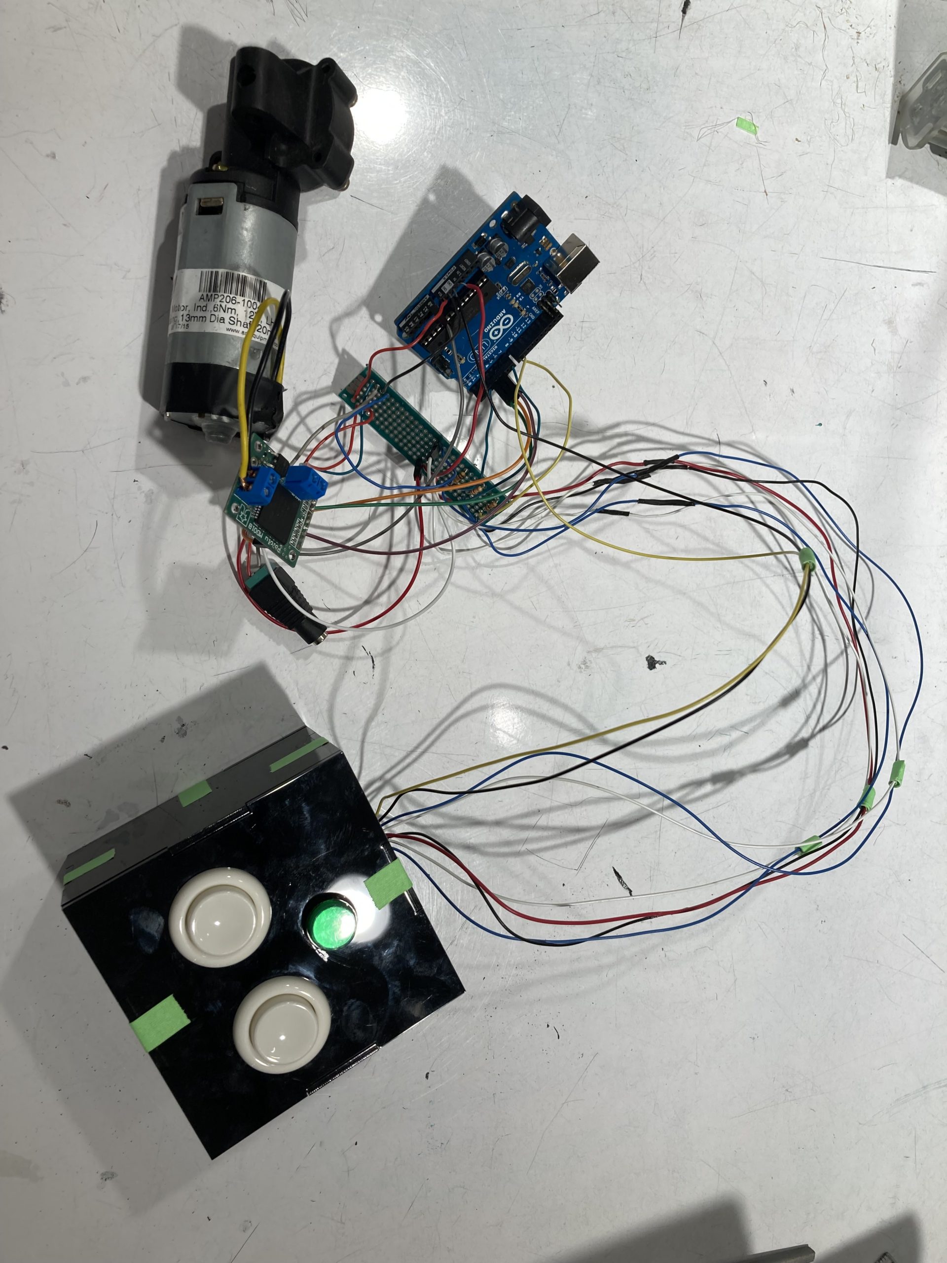
An angle of the motor, motor driver (old Pololu), and Arduino (which would go into the control box) and the control interface (small box), with the external 12V power source connecter still attached
Process update for the control interface box, with old H-Bridge chip, with switches working and assembled
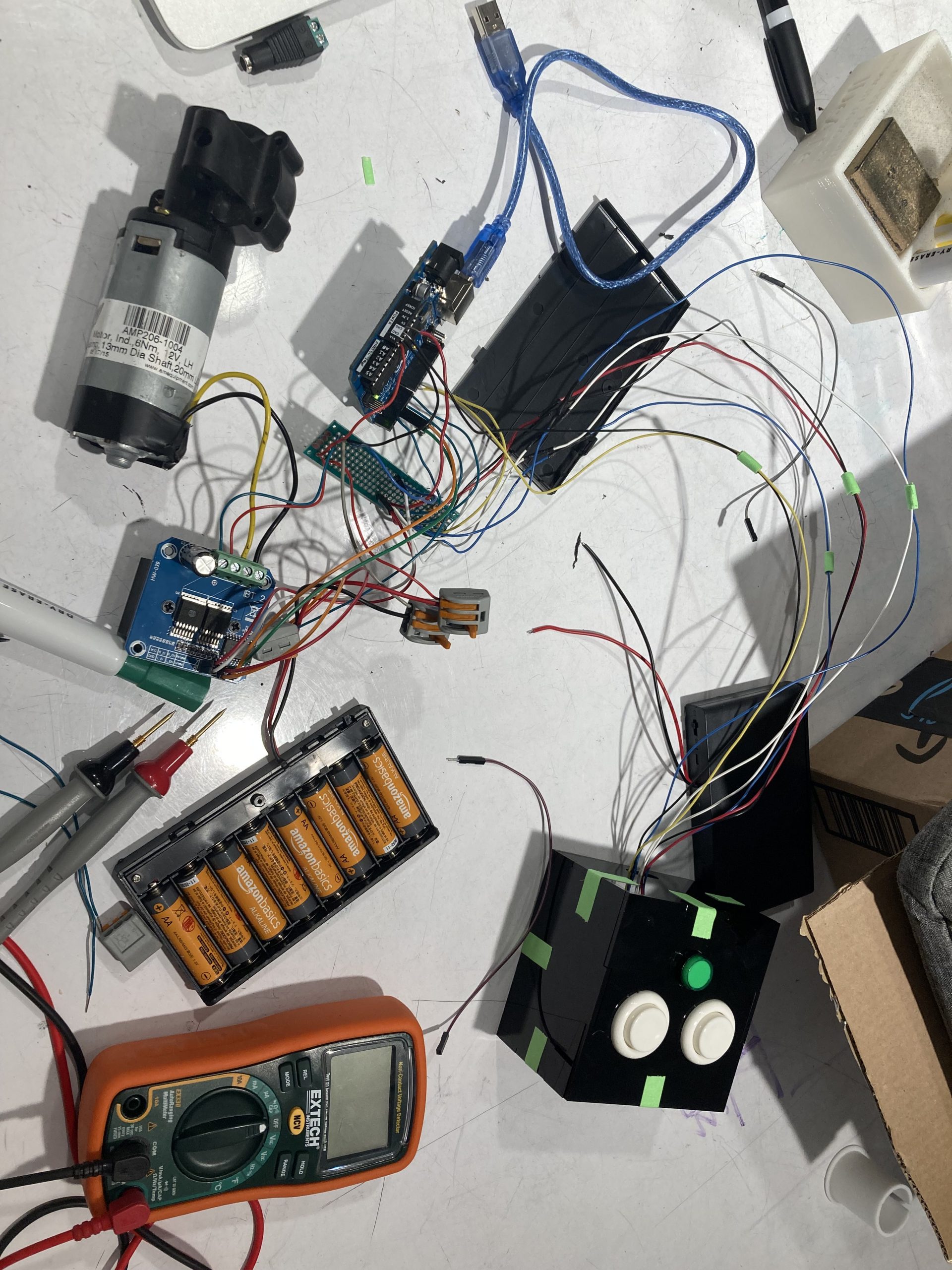
Progress photo of new H-Bridge motor driver connected and operational with new 12V battery pack– temporary connectors still attached and system not soldered yet
Then it came down to fitting all the components into the control box. One big issue we had was attaching the crossbar to the back of the control box and also securing it to the worm motor. This process took a lot of elbow grease (and literal machine grease), soldering, resoldering, and sawing screws and the metal stem of the umbrella.
Drafting work being done to design how the motor and pulley would fit inside the control box and how the control box would be mounted to the back of Brenda’s chair
Progress photo of figuring out how to fit all the components into the control box
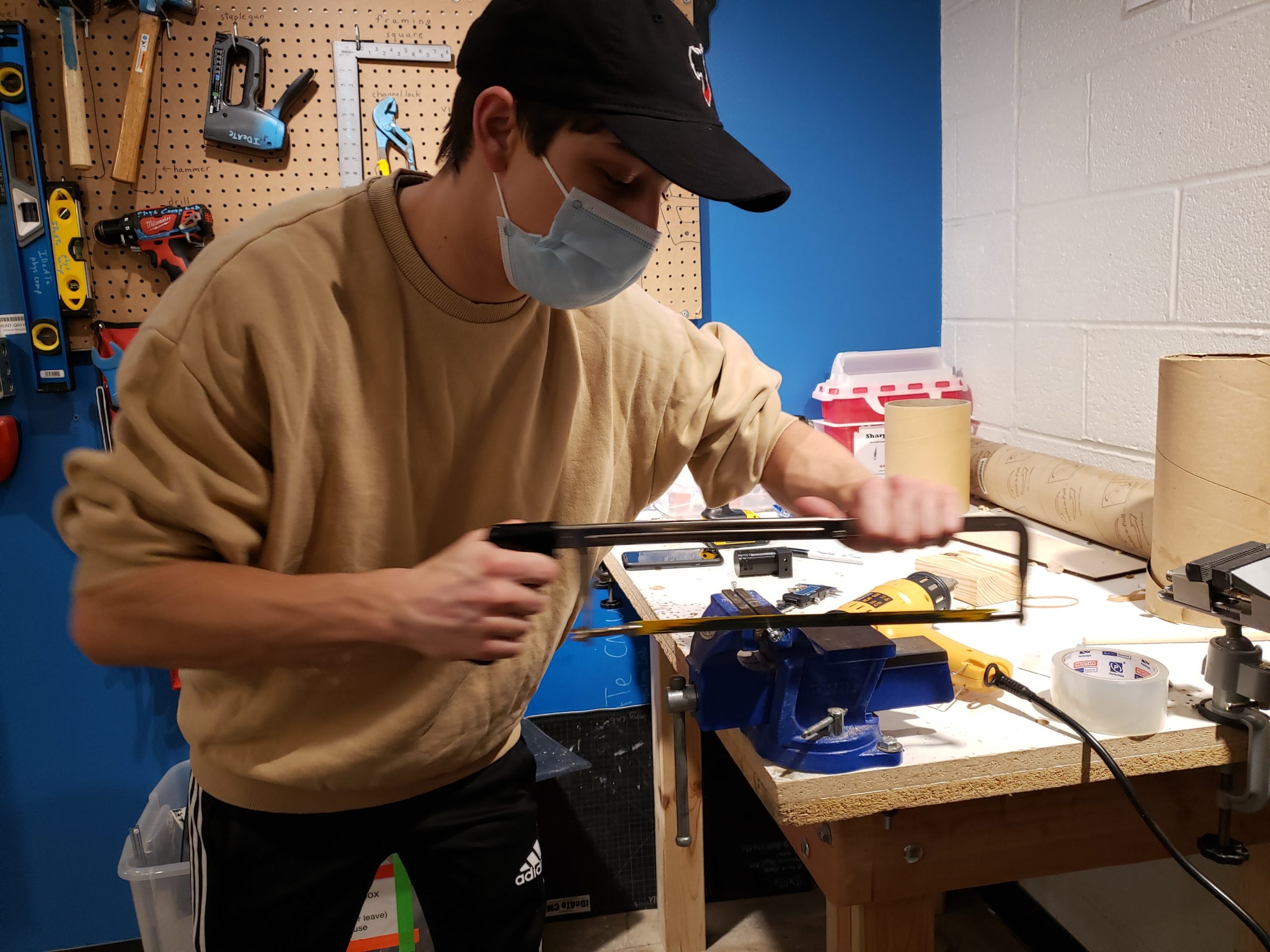
Sawing the screws to the right length in order to slide into the crossbar
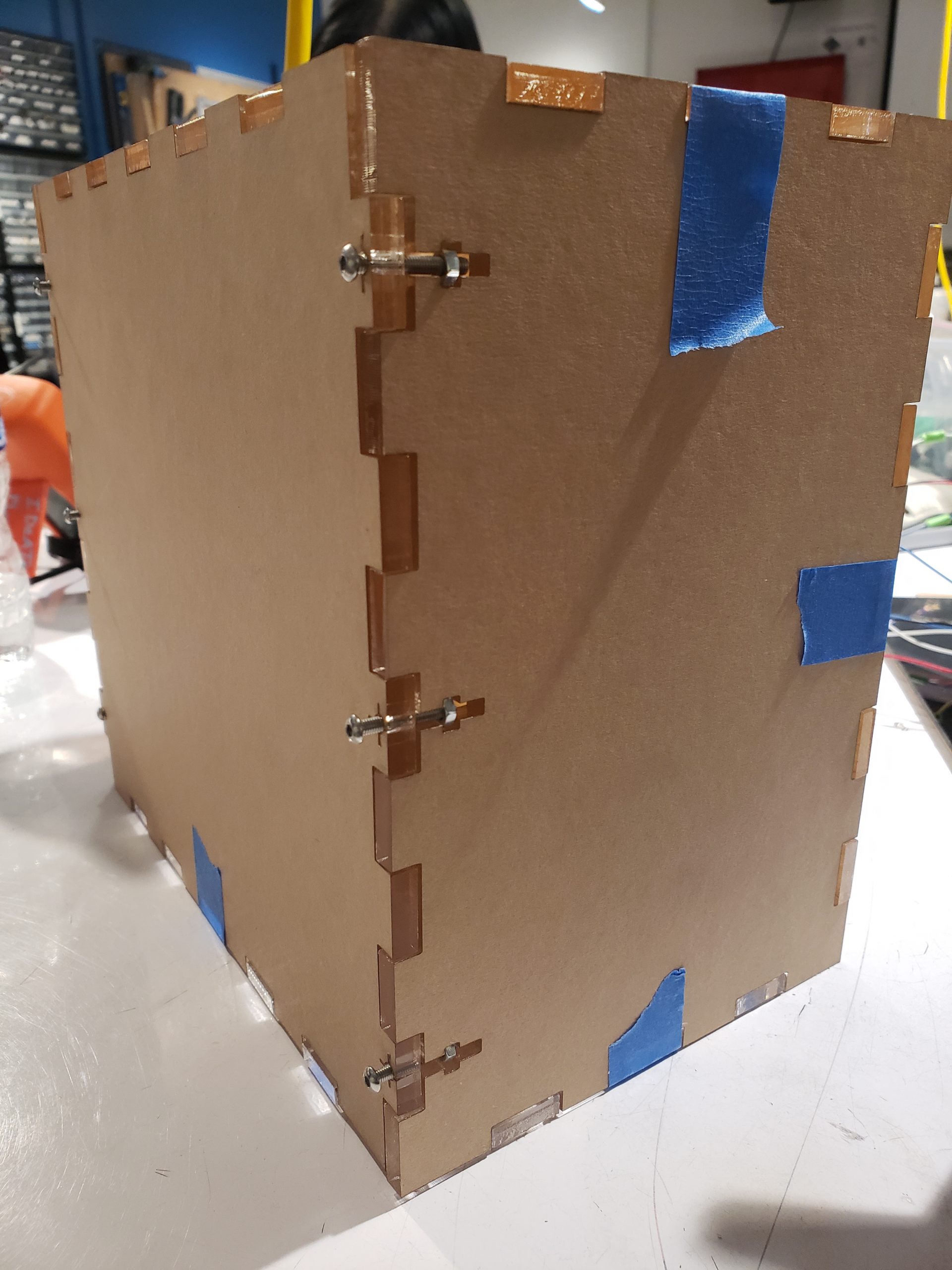
View of screw joints used to hold together control box
Inside view of control box while the motor was being screwed into the backing bar that attached to the back of the control box– copious amounts of motor oil for sliding the screws in not pictured
Throughout the process, we made and learned from our mistakes, discovered new techniques, and encountered many instances of components not working. Some mistakes we made included accidentally soldering all the wires with their extensions without passing them through the slots cut into the bottom of the acrylic control box, which caused a little bit of despair. Other mistakes included not making the tolerance of the 3D printed parts correct. The base that would slide onto the bottom of the umbrella stem and hold the control box wasn’t large enough and got stuck before sliding up all the way and we ended up having to saw off the plastic from the base of the umbrella and reprint the part. Additionally, the parts comprising the pulley at the apex of the umbrella were printed too large and did not secure onto the diameter of the pole as snugly as we would have hoped, so that was another part we had to remeasure and reprint. In addition to our components being ill-fitting, we also had issues with wire connections and soldering– at points the soldering in the wire extensions was not electrically connected and we had to spot check each wire to isolate which connection was not secure and thus causing the motor to continue rotating past the fully extended distance and nearly breaking our pulley system.
Some discoveries made included managing the H-Bridge motor driver. At first, using the one from IDeATe Lending was a little complicated as we had to figure out how to wire the motor to the chip, and at one point our entire group plus Catherine and Zach experimented with being human resistors. Once we finally sorted out the wiring, Zach simplified our code more by having us just drive one signal high and the other low and vice versa to switch the motor direction, and both low to stop the motor rather than using library functions which would be only applicable to the specific type of chip we had. Then, we had to figure out if a cheaper alternative to the H-Bridge motor driver from IDeATe Lending that we were using could be feasibly constructed from a series of transistors. Although we experimented with using MOSFETS as current switchers, in the end the homemade H-Bridge had to be scrapped since resources online which outlined such DIY H-Bridges utilized BJTs rather than MOSFETS, which is all the Physical Computing lab had. Although the components are similar, their electronic behavior was just different enough to be too complicated to transfer the wiring from one transistor type to another. We ended up ordering a cheaper high current H-Bridge, which then still took some trial and error to re-figure out the wiring for.
In terms of following schedules, we planned out a Gantt chart which may have been a little too ambitious:
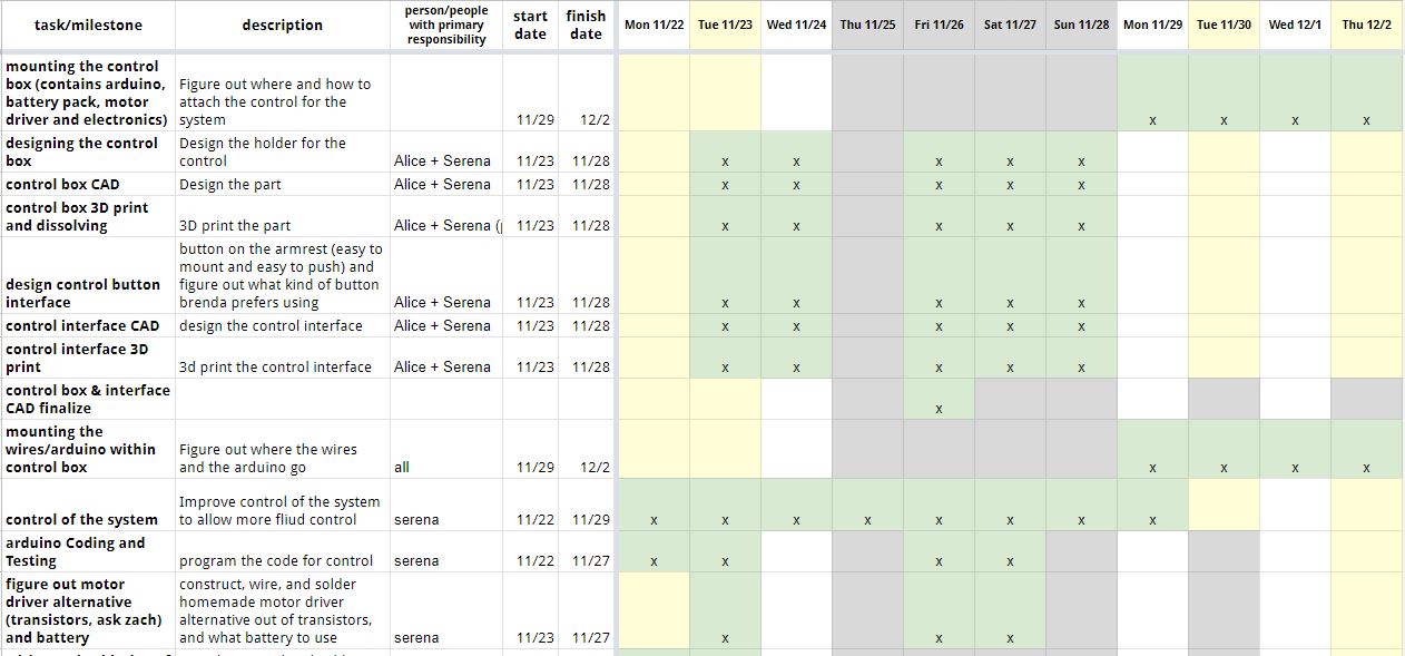
A snippet of our Gantt Chart
Although we tried our best to stay on schedule, we encountered setbacks from having to wait for 3D printers to be available, different replacement components to come in, and for delays with 3D prints not being started as scheduled or TechSpark being closed unexpectedly. In this way, our work ramped up as the deadline approached and included a few long work sessions the nights before, as well as one particularly late night the night before presentations. Overall though, other than delays caused by materials not being usable in time, we kept on track for our designing benchmarks and were able to put everything together in time once we had our hands on the right materials.
4. Conclusions and Lessons Learned
Responding to Some Feedback
“The buttons are a little bit confusing some way of differentiating between them would be helpful” We were planning to position the box in a way that would have one button on the top and one on the bottom, so then the direction of control would align with the position of the button. However, we agree that it would be even better to distinguish the buttons with differently shaped buttons. That way the user can instantly know which button is for which direction, instead of fumbling around to see where the button is located.
“The box attached to the umbrella is a little too big, but again it’s a prototype; the size of the black rotating rod limited the compactness…” Yes, the size of the box is indeed on the bigger side. We actually had to adjust where it’s located due to the size. It was originally going to be located toward the top of the chair near the headrest. This suggestion of using a smaller rotating rod would definitely help reduce the size of the box.
“The hardest part of robotic umbrellas (surprisingly I have experience here) is with making them close again. This team was able to figure out a way to deal with that, and it impresses me.” Thank you! Figuring out how we make the umbrella closes was definitely a big part of our initial discussions. We were originally going for a rack and pinion mechanism, however we realized, with the help of our professor, that we can use the help of gravity. So, we went ahead and found an umbrella that closes with gravity which simplified our design.
“Auto stopping–>needs to count rotations or measure stall voltage on motor” This was definitely something we were planning to do but did not get the chance to. The next step, for safety reasons, would be implementing some sort of stop/limit switch, so the motor will only be activated for enough time to just open up and close the umbrella. The stall voltage suggestion is an interesting idea to try implementing.
“The team has a problem I’ve had for years- overdesigning. By being as strict in designs to Brenda’s chair specifically, it can only ever work for HER chair. By having a looser design, more people could potentially use it.” Like mentioned above in our prototype feedback, this is something we are aware of. The current design might be hard even for Brenda to change the umbrella to a different one. One suggestion we got from the final critique was to reconsider how we attach the system to the chair by using a tripod-like mechanism: have one side always fit for our umbrella holder and the other adjustable for different kinds of chairs.
Experience of Working Remotely
Fortunately, the working experience is mostly hybrid for this project. We were able to meet in person and only went remote when needed. The most challenging aspect was communicating effectively when not in person. There were times when we needed Brenda’s input, and it took many text messages to sort it out. It was also frustrating at the beginning of the project when we were unable to get hold of Brenda. Despite all these, we were able to find compromises and move forward with the project. In retrospect, it is really important to plan for the in person opportunities we do have. If we have thought more about questions to ask her and measurements to take, we might have been able to minimize the need to communicate virtually.
Working with a Person with a Disability
One takeaway is that when designing for people with disabilities, designers need to keep in mind the clearance issue. Power chairs are already bulky enough, it would be ideal to avoid making them bigger, especially horizontally. We had to carefully think about the placement of the control because of this. Nevertheless, I have to say, although designing for disability has its own special things, it is also really not that different from just designing for people. What surprised me is how this project can appeal to a broader audience. There was one comment from our critique saying “I needed this walking to class when I was in school” and I personally would love to have this umbrella retraction system for the porch umbrella my family has. Universal design is really the golden standard all designers should follow.
Concluding Thoughts
To conclude, one last lesson we would like to mention is how iteration is an essential part of the design. People shouldn’t rely on things working out the first time they try, and we should plan for failures and redesigns. Our reprint of parts, reconnecting the wires, redesign of the box and more taught us too well of this lesson.
5. Technical Details
Block and Schematic Diagrams

Block Diagram

Schematic
Code
/*
   Automated Umbrella

   This code drives a motor CW or CCW by sensing up and down button presses. The up
   and down button presses are only registered when an overall on switch has been
   engaged. While the overall on switch is engaged and the motor is not running,
   a buzzer will sound an arpeggio as an alert tone to warn the user that the up
   and down buttons are active and can be engaged. The motor is driven CW or CCW by
   driving its IN_A and IN_B pins either high or low-- IN_A being high and IN_B
   being low or vice versa indicate the motor being driven in one direction, or
   both pins driven as low indicates the motor is stopped. The pins will never be
   both driven as high (illegal).
*/

/*
   ------------------------------------------------------------------------------
   Pin Mapping
   ------------------------------------------------------------------------------

   Name             Pin             In/Out
   IN_A              3               OUT
   IN_B              4               OUT
   PWM               5               OUT
   BUTTON_UP         2               IN
   BUTTON_DOWN       7               IN
   BUTTON_ON         8               IN
   BUZZER_PIN        9               OUT
*/

/*
   Credits:

   https://arduinogetstarted.com/faq/how-to-use-buzzer-without-blocking-other-code
*/

#include <ezBuzzer.h>


// motor pins
#define IN_A 3    // pwm pin motor (digital output)
#define IN_B 4    // control pin INA (digital output)
#define PWM 5    // control pin INB (digital output)

#define BUTTON_UP 2
#define BUTTON_DOWN 7
#define BUTTON_ON 8

#define BUZZER_PIN 9

ezBuzzer buzzer(BUZZER_PIN); // create ezBuzzer object

// notes in the buzzer melody
int melody[] = {
  NOTE_C4, NOTE_E4, NOTE_G4, NOTE_C5
};

// note durations: 4 = quarter note, 2 = half note
int noteDurations[] = {
  4, 4, 4, 2
};

//Variables representing state
bool up_state = 0;
bool down_state = 0;
bool on_state = 0;
unsigned long timer = 0; // used for speaker delay


// Helper functions for driving motor
void motor_stop() {
  digitalWrite(IN_A, LOW);
  digitalWrite(IN_B, LOW);
  analogWrite(PWM, 0);
}

void motor_cw() {
  digitalWrite(IN_A, HIGH);
  digitalWrite(IN_B, LOW);
  analogWrite(PWM, 255);
}

void motor_ccw() {
  digitalWrite(IN_A, LOW);
  digitalWrite(IN_B, HIGH);
  analogWrite(PWM, 255);
}

void setup() {
  pinMode(BUTTON_UP, OUTPUT);
  pinMode(BUTTON_DOWN, OUTPUT);
  pinMode(BUTTON_ON, OUTPUT);
  pinMode(BUZZER_PIN, OUTPUT);
  pinMode(IN_A, OUTPUT);
  pinMode(IN_B, OUTPUT);
  pinMode(PWM, OUTPUT);
  //Initial state of motor
  motor_stop();
}

void loop() {
  up_state = digitalRead(BUTTON_UP);
  down_state = digitalRead(BUTTON_DOWN);
  on_state = digitalRead(BUTTON_ON);
  // If overall on switch is activated (button will latch)
  if (on_state) {
    // If up button is registered, stop motor and then turn CW
    if (up_state) {
      buzzer.stop();
      motor_cw();
      delay(500); // delay for motor
    }
    // If down button is registered, stop motor and then turn CCW
    else if (down_state) {
      buzzer.stop();
      Serial.println("down");
      motor_ccw();
      delay(500); // delay for motor
    }
    // If neither button is registered, stop motor and loop buzzer alert
    else if (!up_state && !down_state) {
      buzzer.loop(); // called to play in the background
      motor_stop();
      delay(500); // delay for motor
      // if buzzer isn't currently playing anymore and 0.5 second has passed, repeat
      if (buzzer.getState() == BUZZER_IDLE && (millis() - timer) > 500) {
        int length = sizeof(noteDurations) / sizeof(int);
        buzzer.playMelody(melody, noteDurations, length); // playing
        timer = millis();
      }
    }
  }
}